Swelling and evaporation determine surface morphology of grafted hydrogel thin films
Abstract
We experimentally study the formation of surface patterns in grafted hydrogel films of nanometer-to-micrometer thicknesses during imbibition-driven swelling followed by evaporation-driven shrinking. Creases are known to form at the hydrogel surface during swelling; the wavelength of the creasing pattern is proportional to the initial thickness of the hydrogel film with a logarithmic correction that depends on microscopic properties of the hydrogel. We find that, although the characteristic wavelength of the pattern is determined during swelling, the surface morphology can be significantly influenced by evaporation-induced shrinking. We observe that the elastocapillary length based on swollen mechanical properties gives a threshold thickness for a surface pattern formation, and consequently an important change in morphology.
pacs:
??Introduction – Smart hydrogels that respond to external stimuli enable the design of adaptive surface coatings [1, 2]. For example, grafted films of temperature-responsive hydrogels [3, 4, 5] have been used in switchable microfluidic valves with rapid, reliable, and repeatable actuation [6, 7] and to trap single cells [8]. These applications harness volume changes for functionality by exploiting the ability of polymers, in these cases poly(N-isopropylacrylamide) (PNIPAM), to swell in water, by about a factor 4, at room temperature [9]. The resulting hydrogel exhibits a temperature-controlled transition between a swollen state, showing hydrophilic properties and elastic moduli in the kilopascal range, and a collapsed state, caracterized by a hydrophobic behavior and a 100-fold stiffness increase [10, 11, 9, 12]. The switchable physico-chemical properties of PNIPAM led to design media for controlled release in drug delivery systems [13]. Furthermore, biocompatibility of PNIPAM is exploited by using films as substrates for cellular cultures and protein adsorption, as a bioscaffold in tissue engineering applications [14].
Many of these applications require grafting the polymer to a substrate. Such grafting can constrain the swelling of hydrogel films and lead to surface patterning. Indeed, volumetric expansion associated with osmotic pressure is inhibited laterally by substrate-attachement. This geometrical frustration generates an in-plane compressive stress that can destablize the flat surface of the hydrogel [15, 16, 17, 18, 19]. This nonlinear instability [20, 21, 22] renders the surface topography non-uniform, with sharp ‘creases’ (localized regions of large strain/curvature [23]) separating smooth peaks [24, 15, 25]. Such creases are schematized in Figs. 1A and B.
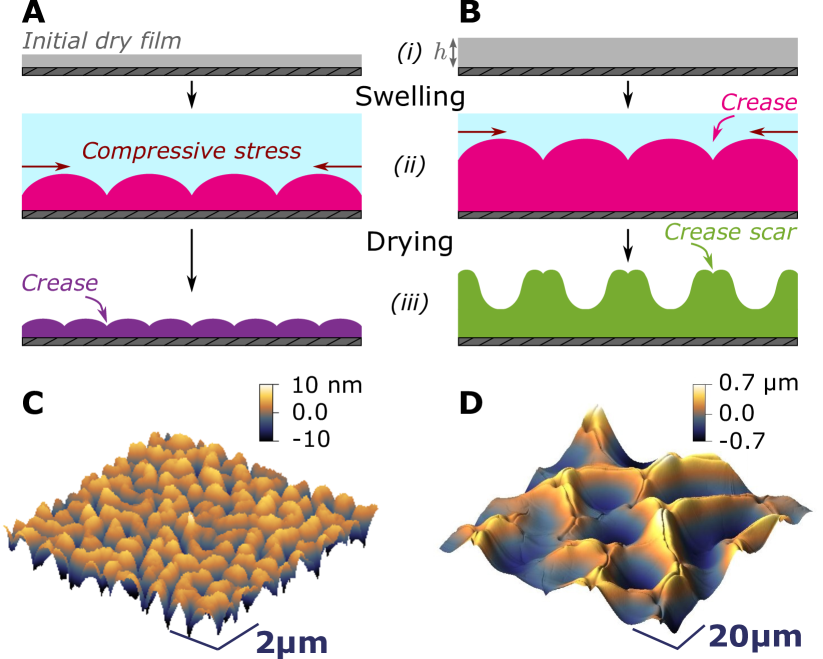
To date, the majority of the reported surface patterns occurred in wet hydrogel films of micrometric-to-millimetric thickness [26, 27, 28, 3, 29, 15, 30]. Here, we report on a morphological transition on nanometric-to-millimetric gels that occurs upon drying, as illustrated in Figs. 1A and B schematically, and in C and D from atomic force microscopy (AFM).
Surface patterns in soft cross-linked gels were first reported over a century ago [31] and in swollen rubber in the 60’s [32]. A first theoretical prediction for surface instabilities occurring under in-plane compression was made by Biot [33]. In this prediction, on the condition that the in-plane strain exceeds a threshold of 0.46, an elastomeric half space deforms in a sinusoidal pattern, referred to as ‘wrinkles’ [34, 33]. Later, Tanaka and co-workers investigated the formation and evolution of creases at the surface of synthetic gels during swelling [26, 27]. Unlike wrinkles that exhibit a sinusoidal shape, creases are characterized by localized regions of large, in-depth, surface curvature.
From the first observations of creases at surface of gels and elastomers, further theoretical and numerical works [22, 35, 16] as well as experimental works [15, 21] showed that the creasing instability occurs at a critical strain threshold of . We note that this latter threshold is lower than Biot’s earlier prediction, suggesting that creases appear before wrinkles as strain increases [18, 23]. The creasing instability is triggered by imperfections, experimentally in the form of nanoscale roughness and numerically by introducing defects [36, 23, 37, 4]. The singular deformation of a crease requires the bulk elastic energy to overcome the barrier of surface tension. The elastocapillary length introduces a lengthscale at which the surface tension and the shear modulus are balanced. Creasing thus releases compression, and produces topographic variations that are reminiscent of the structural architecture of the brain [22, 35, 38]. Swelling-induced creases have been observed in many soft and swollen materials [5, 31, 26, 27, 17, 39, 32, 40, 15, 19] as well as in compressed elastomers [21, 23, 41, 42], that are thicker than the elasto-capillary length. In the latter case, destabilization of the surface is reversible as compression is released. In the following paragraph, we highlight the irreversible character of several swelling-drying processes.
In contrast to swelling matter, drying of complex liquids has been a subject of interest for droplets [43, 44, 45, 46] and films [47, 48, 49, 50]. Drying of solutions found application in the development of the spin-coating technique [51] or in the study of the drying and shrinking of food products [52]. Deswelling of hydrogels has received less attention in the literature than swelling, and previous studies have focused on macroscopic systems [53, 54, 55]. Although in a drying process the ambient conditions and the initial and final states are precisely reversed compared to swelling, drying is only the reverse process of swelling if it occurs very slowly and if elastic deformations are small with respect to the gel size [53]. Nonlinearities that arise through large deformation can render swelling and deswelling as asymmetric processes [53, 54]. These result in non-reciprocal and irreversible deformations in a single swelling-deswelling cycle [5].
In particular during swelling, the intake of solvent takes place from the free surface and the swollen hydrogel near the surface thus become more permeable. In contrast, evaporation reduces the fraction of solvent, may even lead to an inhomogeneity of solvent concentration with enhanced polymer concentration at the surface [56, 49, 43, 57], and thus slower dynamics for the solvent in the near-surface region. The latter phenomenon is reminiscent of the accumulation of solute near the contact line found in drying of thin films of colloidal solutions [56, 49, 58, 57]. Phase changes, such as glass transition may occur [48, 46, 44] in a region localized near the surface of polymer films, leading to the formation of a skin layer or “crust” [48, 50, 59, 46], akin to that seen in drying sessile drops with a pinned contact line [56, 44, 60, 61, 62, 63]. Buckling instabilities, which are characterized by the whole surface between two pinned lines growing and becoming more curved, have been reported for drying polymer films [64, 59, 46] and colloidal solutions [64, 65, 66], and non-uniform drying may even generate complex structures on dry films such as rings [67, 68, 69] or cracks [70, 49], among other patterns [43, 60]. However, creased patterns on dry films, specifically, have been rarely reported [17, 71].
Although characteristic features of the creasing instability can be observed in experiments, the mathematical modeling of the phenomenon is challenging. Intrinsic non-linearity is revealed by the singular shape, then classical linear stability analysis has to be complemented by introducing nucleation and taking into account capillarity in boundary conditions [16, 37, 23, 5, 21]. The latter capillarity involves the effective surface tension between air and the imbibing solvent [72]. A macroscopic wavelength of instability [73] for uniaxial swelling of hydrogels under geometric constraints is identified and roughly scales linearly with the thickness. A finer scaling includes a logarithmic correction, comparing the thickness to the dry elasto-capillary lengthscale , given by the ratio between the effective surface tension between the swollen gel and air and the shear modulus of the solid in the initial dry state [74, 75, 23, 76, 77]. The model of Dervaux, Ben Amar and Ciarletta [72, 73] compares favorably with patterns in swollen films, experimentally performed with an imposed volumetric growth [26, 27, 28, 3] and an imposed chemical potential [29].
The article is organized as follows: we first describe the sample fabrication and the AFM-based measurement technique. We then investigate typical AFM images of dry and wet PNIPAM films, showing a transition from a creased pattern to a more sinusoidal morphology with what we refer to as crease scars. We present a quantitative analysis of these results and discriminate different regimes associated with specific morphologies. We show that hydration-dependent elastic properties determine thresholds for pattern apparition. We finally discuss the role evaporation may play, in determining the final surface morphology.
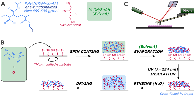
Experiments – We prepare PNIPAM surface-grafted hydrogel films using the procedure outlined in Fig. 2 (see supplementary information, SI, Sec. I.A-D for further details). A in-house synthetized PNIPAM, functionalized with ene-reactive groups (weight-average molar mass g/mol, polydispersity index about 2) [9], is used throughout this study. Uniform films of ene-functionalized PNIPAM are produced by spin-coating from a solution onto the surface of thiolated substrates (silicon wafers or glass substrates). Two orders of magnitude in film thickness are achieved by spin-coating at different angular velocities, from 1000 to 4000 rpm, and by varying the PNIPAM concentration in the initial polymer solution, from 0.5 % to 15 % (w/w, see SI, Sec. I.C). The hydrogel coating is cross-linked under deep-UV insolation (see SI, Sec. I.D). To remove the excess crosslinker and to induce swelling, samples are immersed in deionized water for 4 h then in isopropanol (HPLC grade) for 15 min. Finally, the samples are dried under ambient conditions.
The surface topography of dry and wet films is measured using an Atomic Force Microscope (Nanosurf CoreAFM). The average thickness and Young’s modulus of dry and wet films is also measured by AFM, after a scalpel is used to cut a line across the dry hydrogel film, exposing the substrate.
The wavelength and amplitude of patterns are extracted from line profiles of the surface topography; reported values for any sample constitute an average of 10-20 line profile measurements (see SI, Sec. III.A).
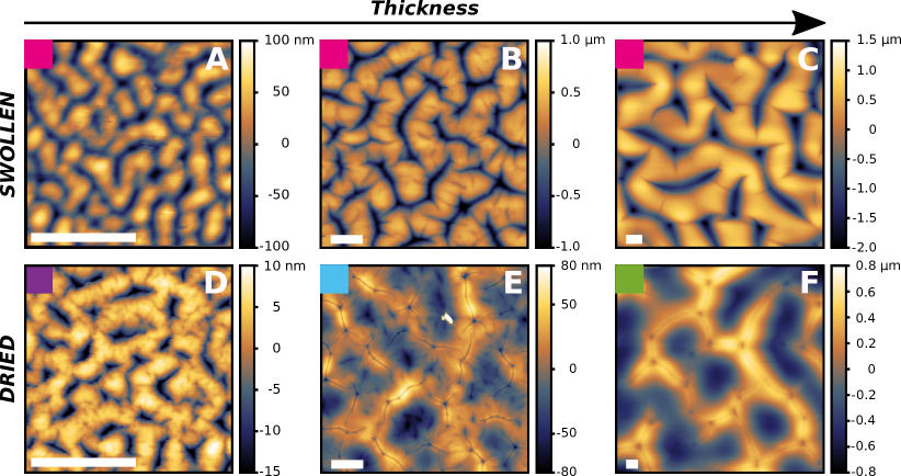
Results – Typical AFM images of grafted PNIPAM films of different thicknesses are shown in Fig. 3: the surface topography and the thickness of three different samples is presented in both wet and dry conditions. During the fabrication process, such patterned morphologies appear only after the first exposition to a solvent rather than during UV irradiation (Fig. 2 and see SI, Sec. II.A). The first solvent in which swelling occurs and any subsequent drying process selects once and for all the pattern observed after drying. For example, swelling in a second solvent, and repeated swelling and drying cycles, do not change the pattern (see SI. Sec.II.B). These observations suggest that surface patterning occurs in our samples as a substrate-attached hydrogel swells due to solvent imbibition, rather than because of a depth-wise gradient in crosslinking density during UV curing [5, 79, 80, 81]. While we focus on the dependence of pattern morphology on film thickness, the influence of UV-irradiation time, substrate type, swelling solvent quality and vapor saturation of ambient air were also investigated as detailed in SI, Sec. II.B. We observed that the pattern formation was independent of substrate type (silicon or glass as in SI, Sec. I.D). The averaged rinsed-film thickness was independent of UV-irradiation time provided exposure exceeded 1.5 h (see SI, Sec. I.D). The influence of the evaporation rate was investigated by saturating the ambient air in water vapor to slow down the evaporation. We observed that slow evaporation did not affect pattern formation (see SI, Sec. II.B). Finally, we observed that the shape and amplitude of surface patterns are fixed after the first exposure to a rinsing solvent after UV insolation. In particular, once formed, patterns are identical upon subsequent swelling-and-drying cycles (see SI, Sec. II.A). These observations are consistent with descriptions of swollen gels in literature [77] and contrast with the one of compressed elastomers which exhibit reversible creases.
Examples of the measured surface patterns shown in Fig. 3 evidence a dependence of the surface topography on the initial thickness of the film. The observed surface patterns were classified by morphology as indicated by the colored squares in Fig. 3, and detailed in SI, Sec. III. Two types of morphology with an intermediate regime are identified. In the case of wet films shown in Figs. 3A-C and dried nanometric films in Fig. 4D, the surface patterns resemble the brain-like patterns. These patterns are typical of a surface-creasing instability found in an elastomer subject to in-plane mechanical compression or a swollen hydrogel [26, 27, 28, 3, 29, 15, 72, 73, 30, 23, 5, 17]. The topographies comprise smooth upper peaks separated by sharp plunging creases. The thickest film shown in Fig. 4F displays a topography that is distinct from the brain-like pattern, with broader valleys surrounding sharper peaks. We term this morphology the “volcano” pattern since a small-amplitude crater is observed at the peak summits.
The average thickness of both wet and dried films was measured. Surface patterns were only observed in dried and wet films with an initial thickness greater than nm (see SI, Sec. II.A). We note that swelling is strongly affected by the surface attachment for ultrathin PNIPAM films [9]. For films investigated here with nm and 3 h irradiation time, a swelling ratio (i.e. the ratio between the swollen thickness of the hydrated gel and the dry thickness) of about was observed. This value of swelling ratio is consistent with results from Li et al. [9] and corresponds to a mechanical strain of about 0.62, taking a Poisson ratio of for PNIPAM [82, 83]. Yet, the swelling ratio decreases monotonically with thickness below nm: this suggests that osmotic stress may be insufficient to produce a mechanical strain above the threshold of [22, 35, 16, 15, 21], corresponding to a swelling ratio of 2.4, for creasing in films with a thickness of a few tens of nanometers.
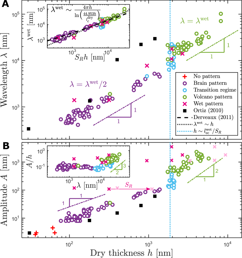
From surface topography measured by AFM, patterns were characterized quantitatively by measuring the wavelength and amplitude as well as the thickness , in both wet and dry conditions. The wavelength and amplitude of the instability are respectively shown as functions of the initial, dry film thickness in Figs. 4A and B. For wet films, the wavelength increases monotonically with the initial, dry thickness. For dried films, a transition region exists between the two morphological regimes mentioned above. With increasing thickness, the wavelength is multiplied by a factor 2, at a critical thickness that we will discuss in the next section. In the thick-film regime, the wavelength of the wet pattern is comparable to that of the dried pattern, while in the thin-film regime the wavelength of the wet pattern is roughly twice the wavelength of the dried pattern (Fig. 4A). The results of Ortiz et al. [17], attained with dried, thin films of PNIPAM copolymerized with methacroyloxybenzophenone (MaBP), are also included in Fig. 4A and B, for reference and are mainly consistent with our results, as we discuss in more detail in the next section.
To characterize the threshold for the formation of volcano patterns on dried films, that marks the transition between the two observed regimes, we measured the material properties of PNIPAM hydrogels in the wet state, using AFM. The Young’s modulus in the swollen state was measured to be kPa (see SI, Sec. III.B). This value is larger but on the same order of magnitude than values from literature ( kPa), which may be due to the use of an indentation-based technique [84, 12]. Recalling that the shear modulus is expressed as , we then calculated the elastocapillary length m, with the shear modulus in the wet state. This elastocapillary length is based on wet mechanical properties of PNIPAM. Values were taken from literature for: the surface tension mN/m [85] between swollen PNIPAM and air, and the Poisson’s ratio [82, 83] of PNIPAM in the swollen state and at room temperature.
Finally, from AFM images presented in Fig. 3 the pattern amplitude was also measured as a function of the initial dry thickness and is presented in Fig. 4B. First, a nanometric surface roughness is measurable as for dried, ultra-thin samples that exhibit no pattern. Then for samples thick enough to exhibit a pattern ( ), the pattern amplitude of dried films as a function of the initial film thickness switches from a linear behavior to a power law dependency at the same critical thickness as the transition in morphology, as shown in Fig. 4B. The result of Ortiz et al. on dried films are included for comparison [17]: the amplitude roughly exhibits the same linear dependency in thickness. The pattern amplitude of wet films as a function of initial film thickness shows at first sight a linear behavior (see Fig. 4B, magenta crosses), but swelling induces a prefactor in thickness (see Fig. 4B, light pink crosses).
For wet samples, the amplitude as a function of the wet thickness exhibits a linear scaling, similarly to the amplitude measured on dried brain-like patterns as a function of the initial dry thickness , and with a similar prefactor. Thus, the ratios between dried or wet amplitude and dried or wet thickness, respectively, appears as a relevant quantity to investigate. In the inset of Fig. 4B, the ratio between amplitude and film thickness is represented as a function of the wavelength measured on each sample. The ratio between amplitude and initial film thickness shows no dependency on the wavelength for brain-like patterns, while for volcano patterns an increase in a power law is observed, with an approximate 3/2 exponent (Fig. 4B, inset). This latter dependency is expected to saturate as the film thickness is increased even further than here, since the pattern amplitude should not become considerably larger than the undisturbed film thickness. Otherwise, more complex surface patterns such as folds may be observed as was reported elsewhere [86, 25]
From these observations, we conclude that surface creasing results from swelling and the wet-state properties select a particular wavelength of the observed instability. In the case of wet gels, the amplitude of instability scales with the wet thickness. However, drying may: (i) affect the wavelength, dividing it by a factor two in the case of thin gels, (ii) modify strongly the morphology, and thus the amplitude dependency in the case of thick gels. In the next part, we discuss the thresholds in thickness for the occurrence of patterns observed on dry films, and we speculate on the origins of the morphologies. Furthermore, we compare quantitatively our experimental results on wet films with a theory proposed by Dervaux and Ben Amar [73]. Finally, we identify key ingredients and propose a mechanism explaining the emergence of the volcano pattern observed on dry films.
Discussion – Thickness thresholds for morphology change: A threshold thickness of about for the creasing instability is observed and was also reported in [87], for a given degree of cross-linking. This threshold is related to the thickness-dependent swelling ratio and thus to the volume strain. For these small thicknesses, this swelling-induced strain is not large enough to overcome the subcritical bifurcation inherent to the creasing instability [22]. Then, at larger thicknesses, a second threshold thickness of about for the apparition of the volcano pattern is observed on dried films.
To rationalize this second threshold, we estimate the elastocapillary length based on the mechanical properties of the fully saturated gel, and when the swollen gel dries in contact with ambient air. This length is thus computed to be: . The swelling ratio was estimated to be about by AFM. Scaled by the swelling ratio, the wet elastocapillary length becomes finally m. After drying, the critical initial dry thickness at which a the pattern morphology transition, from brain-like to volcanoes, is observed to be m. Taking into account a small overestimation of the Young’s modulus due to the indentation measurement technique [12, 84], thus an underestimation of the elastocapillary length, the dry thickness at which the transition occurs is then comparable to the wet elasto-capillary lengthscale scaled by the swelling ratio. This suggests that elastocapillary effects indeed play a role in the observed transition. Finally, the results of Ortiz et al. [17] also mention a doubling of the wavelength dependency albeit at a different, yet comparable, critical thickness with our estimate of .
One interpretation of the correspondence between the critical thickness for morphology change and the wet elastocapillary length is as follows. The balance between surface tension and bulk elasticity determines the threshold of the surface (de)stabilization: for wet thicknesses smaller than the wet elastocapillary length, i.e. , surface tension dominates and the surface shape is not significantly affected upon drying, resulting in a creased pattern with a different spacing. For wet thicknesses larger than the wet elastocapillary length, i.e. , bulk elasticity dominates and the surface shape is destabilized upon drying, leading to the formation of the volcano pattern.
The volcano morphology observed for micrometric, dried films (Fig. 3F) is distinct from that previously reported in wet millimetric hydrogels films [26, 27, 28, 3, 29]. Indeed, the patterns previously reported in thick wet hydrogel films are more akin to the brain-like patterns observed in nanometric dried films (Fig. 4D). AFM images showing the particular surface shape of the volcano pattern (Fig. 3F) are reminiscent of images shown in the work of Ortiz et.al. [17], however morphology is not discussed therein. The apparent multiscale patterning observed here is reminiscent of period doubling of wrinkle patterns which typically occur in bilayered systems comprising a thin, pre-stretched stiff film upon a soft elastomer [88, 89, 90, 91, 92, 93, 94, 95, 42]. However in the hydrogel films presented here, stresses arise in the whole thickness of the gel during swelling, and are relieved by the formation of creases. We are unaware of any description of period-doubling or period-halving for creases in the literature.
Wavelength selection: We have discussed the final observed morphologies and their thickness apparition threshold. Starting again from the beginning of the process, we now focus on the first swelling phase. We discuss in particular the quantitative measurements of the wavelength as a function of film thickness.
Previous observations of creasing patterns in swollen hydrogel films, similar to our observations of brain-like patterns presented in Figs. 3A, B and C, have been rationalized under the theoretical framework of Dervaux and Ben Amar [73]. The wavelength of the brain-like patterns observed in these swollen, wet systems was found to scale with the initial dry thickness of the hydrogel: , with the elastocapillary length computed in the initial dry state and with a numerical prefactor in the natural logarithm . This scaling implies that regularization at threshold is done by capillarity in an elastic boundary layer of initial size comparable to the dry elastocapillary length. Experimentally, crease spacings were reported to scale linearly with the thickness [87, 29, 17, 30]. Indeed, if the threshold for regularization is small compared to the typical sample thickness, a slight deviation from a linear scaling appears in the thinnest samples still exhibiting a pattern.
To compare our data with the model of Dervaux and Ben Amar [73], we first introduce for dried films the wavelength that is expected in the swollen state, and that was measured for a few samples. For volcano patterns, the measured wavelength in both dried and wet conditions shows no change for a subset of samples, thus we set . For dried brain patterns, however, we measure twice the wavelength of the dried state in the swollen state (see magenta crosses in Fig. 4A), thus we set , where the factor of 2 was verified to be the best fitting value, within error. The wet wavelength is represented as a function of the swollen thickness in Fig. 4A, inset, and shows a small deviation from a linear behavior.
The slight sublinear behavior is captured by the model of Dervaux and Ben Amar: a fit of the data with the scaling including a logarithmic correction results in an estimation of the dry elastocapillary length of and a corresponding shear modulus of (see SI, Sec. III.3 for the estimate precision). This estimation of shear modulus, which lies between the glassy and fully swollen ones measured here (SI, Sec. III.B), is a value that the modulus could take after enough solvent is absorbed by the gel to cross the glass transition. In summary, with our expectation of wavelength in the swollen state, our data for dried samples show an excellent agreement with the theoretical prediction of Dervaux and Ben Amar [73]. We propose the following interpretation: the geometrical expansion due to swelling is large enough to overcome the surface tension, which results in the destabilization of the free surface [76].
In the two previous paragraphs, we rationalized the wavelength measurements of different pattern types in the dry state by linking them with patterns observed in the wet state. Based on these observations, we conclude that the wavelength is set in the wet state, as a result of swelling. In the next paragraphs we examine how the evolution of the pattern shape during drying may proceed.
Morphological evolution upon drying: As liquid evaporates out of the gel, the film passes through a glass transition triggered by dehydration, when the polymer concentration is large enough [96, 97]. Since evaporation takes place from the free surface, at a critical solvent fraction a glassy skin layer is formed [98, 99, 100, 101]. This skin layer first increases in thickness rapidly, and then expands with a diffusive dynamics [101]. In our situation, the initial condition for drying of the swollen hydrogel films is not a flat free surface, as is the common case described in [102]. Instead, the formation of the glassy skin layer due to evaporation takes place from an initially creased surface. We now focus on how such creasing could affect the spatial distribution of polymer within the film at the onset of evaporation. We separate the two different thickness regimes in terms of the elastocapillary length estimated above.
In the first case , surface tension effects dominate elastic stresses in the soft and swollen gel, smoothing out large-curvature features in the gel. In this regime, a drying front propagates in time. The film is thin enough to dry uniformly. Then, smaller wavelength creases become more geometrically favorable due to the basic scaling [73]. However, a wavelength was already selected during swelling (Fig. 1, first column). Therefore, a new wavelength can emerge during drying only when it is an integer fraction of the initial one in the fully swollen state. We observe that a crease wavelength with half the period thus appears on the creased, dried films, during drying. It seems reasonable that either the glass transition, or a crossover into the non-creasing regime of solvent fraction, is reached before a further wavelength reduction could be affected.
In a second case for films with , we propose the following mechanism. Bulk elasticity coming from the swollen gel underneath the surface dominates over surface tension. As the gel dries, a glassy skin layer forms initially at the surface and then expands in time [101]. The skin layer is stiffer than the still-hydrated gel underneath, by up to four orders of magnitude (see SI, Sec. III.2 for the Young’s modulus measurements). Additionally, as drying generates a loss of solvent, the stiff crust would shrink, generating in-plane compressive stresses. Such stresses would pull the surface of the still-hydrated swollen gel underneath. In such a situation, a stretched, stiff and thin layer exists on a thick and soft material. Numerous works have showed that a wrinkling instability can thus appear once a critical compressive strain is exceeded [42, 25, 103, 38, 104, 105, 106, 107, 108, 109, 110]. The surface of the bilayer becomes destabilized, taking a sinusoidal shape, whose wavelength scales as , with and the thicknesses, and the Young’s moduli of the skin and the substrate respectively. In our case, a wrinkling instability could thus appear on an initially-creased surface, with the spatial distribution of solvent and wavelength of wrinkles pre-selected by the creases in the swollen film.
We estimate the thickness of the skin layer at the moment when the critical strain is exceeded using the wavelength of the crease pattern, . We find it to be approximately of the swollen thickness of the film, using and (see SI, Sec. III.2), which is expected to be reached almost instantaneously once the formation of the skin layer is initiated [101]. By opposition to the depth of creases and because of the extreme curvature in the region of the creases [111], the bumped regions are less constrained and thus shrink more during evaporation, which may also occur preferentially from the peaks of the bumps than in the vicinity of the creases [112], possibly creating an inversion of the topography. Indeed we observe the resulting surface morphology to be characterized by a globally-sinusoidal profile, with scars of creases present at the upper regions. Thus the wavelength of the dried volcano pattern is prescribed by the swollen creased patterns initiated in the wet state.
In summary, swelling and drying hydrogels may experience elastic instabilities that affect the surface topography. During swelling the originally flat surface is deformed by an in-plane compressive stress, resulting in the formation of creases. During drying, depending on the balance between surface tension and bulk elasticity, the formation of a thin, stiff and glassy skin layer on the still-hydrated and soft gel may significantly affect the final surface morphology of the dried film. The final surface morphology of dried films can therefore be a brain-like or a volcano pattern and is determined by this drying process, depending on the thickness of the wet film before drying commences.
Conclusions –
We have investigated the irreversible deformation of grafted PNIPAM films, of nanometric and micrometric thickness, caused by imbibition-induced swelling and evaporation-driven shrinking. Relatively thin, nanometric films undergo a swelling instability that leads to a brain-like pattern, typical of surface creasing instabilities and with a set spacing. When drying, the surface morphology keeps the creased shape although the spatial frequency of creases is doubled as compared to the wet state. The new pattern is then locked-in as the film shrinks (through the glass transition) into a dried film. The typical amplitude of these surface patterns with sub-micrometric wavelengths (m) is consistently of the film thickness, independent of the wavelength (see inset of Fig. 4I).
Thicker, micrometric films also develop surface creases because of in-plane compressive forces that result from constrained swelling due to surface attachment. However, drying is known to induce the formation of a glassy skin layer. We propose that this glassy layer is responsible for a subsequent change in topographic morphology, rendering it distinct from the brain-like pattern observed in the wet state.
Data Availability: The reported experimental data are available in the SI.
Funding: The authors acknowledge financial support from the CNRS, and from the Agence Nationale de la Recherche (ANR) under the CoPinS (ANR-19-CE06-0021) grant, the Institut Pierre-Gilles de Gennes (Equipex ANR-10-EQPX-34 and Labex ANR-10-LABX- 31) and PSL Research University (Idex ANR-10-IDEX-0001-02). The authors also acknowledge financial support from the European Union through the European Research Council under EMetBrown (ERC-CoG-101039103) grant. Views and opinions expressed are however those of the authors only and do not necessarily reflect those of the European Union or the European Research Council. Neither the European Union nor the granting authority can be held responsible for them. The authors also acknowledge financial support from the Agence Nationale de la Recherche under Softer (ANR-21-CE06-0029), and Fricolas (ANR-21-CE06-0039) grants. Finally, they thank the Soft Matter Collaborative Research Unit, Frontier Research Center for Advanced Material and Life Science, Faculty of Advanced Life Science at Hokkaido University, Sapporo, Japan.
Conflicts of Interest: The authors declare no conflict of interest and the funders had no role in the design of the study; in the collection, analyses, or interpretation of data; in the writing of the manuscript, or in the decision to publish the results.
Acknowledgements.
The authors are more than grateful to Marjan Abdorahim for sharing her strong expertise on hydrogels. The authors gratefully acknowledge Patrick Tabeling, Ousmane Kodio, Ken Sekimoto, Grae Worster, Joseph Webber, Noushine Shahidzadeh and Romane Le Dizès Castell for insightful comments and fruitful discussions. The AFM work benefited from EUSMI TA support and expertise of Dr. Peisker from Nanosurf. Finally, the authors thank the Soft Matter Collaborative Research Unit, Frontier Research Center for Advanced Material and Life Science, Faculty of Advanced Life Science at Hokkaido University, Sapporo, Japan.References
- [1] T. P. Russell, “Surface-responsive materials,” Science, vol. 297, no. 5583, pp. 964–967, 2002.
- [2] S.-k. Ahn, R. M. Kasi, S.-C. Kim, N. Sharma, and Y. Zhou, “Stimuli-responsive polymer gels,” Soft Matter, vol. 4, no. 6, pp. 1151–1157, 2008.
- [3] C. Li, Z. Hu, and Y. Li, “Temperature and time dependencies of surface patterns in constrained ionic n‐isopropylacrylamide gels,” J. Chem. Phys., vol. 100, no. 6, pp. 4645–4652, 1994.
- [4] J. Kim, J. Yoon, and R. C. Hayward, “Dynamic display of biomolecular patterns through an elastic creasing instability of stimuli-responsive hydrogels,” Nat. Mater., vol. 9, no. 2, pp. 159–164, 2010.
- [5] J. Yoon, J. Kim, and R. C. Hayward, “Nucleation, growth, and hysteresis of surface creases on swelled polymer gels,” Soft Matter, vol. 6, pp. 5807–5816, 2010.
- [6] D. Beebe, J. Moore, J. Bauer, Q. Yu, R. H. Liu, C. Devadoss, and B.-H. Jo, “Free-evolution kinetics in a high-swelling polymeric hydrogel,” Nature, vol. 404, pp. 588–590, 2000.
- [7] N. Idota, A. Kikuchi, J. Kobayashi, K. Sakai, and T. Okano, “Microfluidic valves comprising nanolayered thermoresponsive polymer-grafted capillaries,” Adv. Mater., vol. 17, no. 22, pp. 2723–2727.
- [8] L. D’Eramo, B. Chollet, M. Leman, E. Martwong, M. Li, H. Geisler, J. Dupire, M. Kerdraon, C. Vergne, F. Monti, Y. Tran, and P. Tabeling, “Microfluidic actuators based on temperature-responsive hydrogels,” Microsys. Nanoeng., vol. 4, no. 1, p. 17069, 2018.
- [9] M. Li, B. Bresson, F. Cousin, C. Frétigny, and Y. Tran, “Submicrometric films of surface-attached polymer network with temperature-responsive properties,” Langmuir, vol. 31, p. 11516–11524, 2015.
- [10] F. M. Winnik, “Fluorescence studies of aqueous solutions of poly (n-isopropylacrylamide) below and above their lcst,” Macromolecules, vol. 23, no. 1, pp. 233–242, 1990.
- [11] M. Heskins and J. E. Guillet, “Solution properties of poly (n-isopropylacrylamide),” J. Macromol. Sci. Chem., vol. 2, no. 8, pp. 1441–1455, 1968.
- [12] M. A. Haq, Y. Su, and D. Wang, “Mechanical properties of pnipam based hydrogels: A review,” Mater. Sci. Eng. C, vol. 70, pp. 842–855, 2017.
- [13] N. Peppas, J. Hilt, A. Khademhosseini, and R. Langer, “Hydrogels in biology and medicine: From molecular principles to bionanotechnology,” Adv. Mater., vol. 18, no. 11, pp. 1345–1360, 2006.
- [14] N. E., M. Abdorahim, and A. Simchi, “Smart polymeric hydrogels for cartilage tissue engineering: A review on the chemistry and biological functions,” Biomacromolecules, vol. 17, 10 2016.
- [15] V. Trujillo, J. Kim, and R. C. Hayward, “Creasing instability of surface-attached hydrogels,” Soft Matter, vol. 4, pp. 564–569, 2008.
- [16] W. Hong, X. Zhao, and Z. Suo, “Formation of creases on the surfaces of elastomers and gels,” Appl. Phys. Lett., vol. 95, no. 11, p. 111901, 2009.
- [17] O. Ortiz, A. Vidyasagar, J. Wang, and R. Toomey, “Surface instabilities in ultrathin, cross-linked poly(n-isopropylacrylamide) coatings,” Langmuir, vol. 26, p. 17489–17494, 2010.
- [18] D. Chen, J. Yoon, D. Chandra, A. J. Crosby, and R. C. Hayward, “Stimuli-responsive buckling mechanics of polymer films,” J. Polym. Sci., Part B: Polym. Phys., vol. 52, no. 22, pp. 1441–1461, 2014.
- [19] J. Ju, K. Sekimoto, L. Cipelletti, C. Creton, and T. Narita, “Heterogeneous nucleation of creases in swelling polymer gels,” Phys. Rev. E, vol. 105, p. 034504, Mar 2022.
- [20] P. Ciarletta, “Matched asymptotic solution for crease nucleation in soft solids,” Nat. Commun., vol. 9, p. 496, 2018.
- [21] S. Cai, D. Chen, Z. Suo, and R. C. Hayward, “Creasing instability of elastomer films,” Soft Matter, vol. 8, no. 5, pp. 1301–1304, 2012.
- [22] E. Hohlfeld and L. Mahadevan, “Unfolding the sulcus,” Phys. Rev. Lett., vol. 106, p. 105702, 2011.
- [23] D. Chen, S. Cai, Z. Suo, and R. C. Hayward, “Surface energy as a barrier to creasing of elastomer films: An elastic analogy to classical nucleation,” Phys. Rev. Lett., vol. 109, p. 038001, 2012.
- [24] N. Suematsu, K. Sekimoto, and K. Kawasaki, “Three-dimensional computer modeling for pattern formation on the surface of an expanding polymer gel,” Phys. Rev. A, vol. 41, pp. 5751–5754, 1990.
- [25] B. Li, Y.-P. Cao, X.-Q. Feng, and H. Gao, “Mechanics of morphological instabilities and surface wrinkling in soft materials: a review,” Soft Matter, vol. 8, pp. 5728–5745, 2012.
- [26] T. Tanaka, S.-T. Sun, Y. Hirokawa, S. Katayama, J. Kucera, Y. Hirose, and T. Amiya, “Mechanical instability of gels at the phase transition,” Nature, vol. 325, pp. 796–798, 1987.
- [27] H. Tanaka, H. Tomita, A. Takasu, T. Hayashi, and T. Nishi, “Morphological and kinetic evolution of surface patterns in gels during the swelling process: Evidence of dynamic pattern ordering,” Phys. Rev. Lett., vol. 68, pp. 2794–2797, 1992.
- [28] Y. Li, C. Li, and Z. Hu, “Pattern formation of constrained acrylamide/sodium acrylate copolymer gels in acetone/water mixture,” J. Chem. Phys., vol. 100, no. 6, pp. 4637–4644, 1994.
- [29] H. Gérardin, A. Buguin, and F. Brochard-Wyart, Pattern formation in anti-fog and anti-frost polymer coatings. PhD thesis, 2006.
- [30] K. Durie, M. J. Razavi, X. Wang, and J. Locklin, “Nanoscale surface creasing induced by post-polymerization modification,” ACS Nano, vol. 9, p. 10961–10969, 2015.
- [31] S. E. Sheppard and F. A. Elliott, “The reticulation of gelatine,” J. Ind. Eng. Chem., vol. 10, no. 9, pp. 727–732, 1918.
- [32] E. Southern and A. Thomas, “Effect of constraints on the equilibrium swelling of rubber vulcanizates,” J. Polym. Sci., Part A: Gen. Pap., vol. 3, no. 2, pp. 641–646, 1965.
- [33] M. A. Biot, “Surface instability of rubber in compression,” Appl. Sci. Res. A, vol. 12, pp. 168–182, 1963.
- [34] S. Mora, M. Abkarian, H. Tabuteau, and Y. Pomeau, “Surface instability of soft solids under strain,” Soft Matter, vol. 7, no. 22, pp. 10612–10619, 2011.
- [35] E. B. Hohlfeld, “Creasing, point-bifurcations, and the spontaneous breakdown of scale-invariance,” Ph. D. Thesis, 2008.
- [36] Y. Cao and J. W. Hutchinson, “From wrinkles to creases in elastomers: the instability and imperfection-sensitivity of wrinkling,” Proc. R. Soc. A., vol. 468, p. 94–115, 2012.
- [37] W. Wong, T. Guo, Y. Zhang, and L. Cheng, “Surface instability maps for soft materials,” Soft Matter, vol. 6, no. 22, pp. 5743–5750, 2010.
- [38] T. Tallinen, J. S. Biggins, and L. Mahadevan, “Surface sulci in squeezed soft solids,” Phys. Rev. Lett., vol. 110, p. 024302, 2013.
- [39] M. Guvendiren, J. A. Burdick, and S. Yang, “Solvent induced transition from wrinkles to creases in thin film gels with depth-wise crosslinking gradients,” Soft Matter, vol. 6, pp. 5795–5801, 2010.
- [40] W. R. Drummond, M. L. Knight, M. L. Brannon, and N. A. Peppas, “Surface instabilities during swelling of ph-sensitive hydrogels,” J. Controlled Release, vol. 7, no. 2, pp. 181–183, 1988.
- [41] A. Ghatak and A. L. Das, “Kink instability of a highly deformable elastic cylinder,” Phys. Rev. Lett., vol. 99, no. 7, p. 076101, 2007.
- [42] D. Chen, L. Jin, Z. Suo, and R. C. Hayward, “Controlled formation and disappearance of creases,” Mater. Horiz., vol. 1, no. 2, pp. 207–213, 2014.
- [43] R. D. Deegan, “Pattern formation in drying drops,” Phys. Rev. E, vol. 61, no. 1, p. 475, 2000.
- [44] D. Zang, S. Tarafdar, Y. Y. Tarasevich, M. D. Choudhury, and T. Dutta, “Evaporation of a droplet: From physics to applications,” Phys. Rep., vol. 804, pp. 1–56, 2019.
- [45] K. Ozawa, E. Nishitani, and M. Doi, “Modeling of the drying process of liquid droplet to form thin film,” Jpn. J. Appl. Phys., vol. 44, no. 6R, p. 4229, 2005.
- [46] L. Pauchard and C. Allain, “Stable and unstable surface evolution during the drying of a polymer solution drop,” Phys. Rev. E, vol. 68, no. 5, p. 052801, 2003.
- [47] P.-G. De Gennes, “Instabilities during the evaporation of a film: Non-glassy polymer+ volatile solvent,” Eur. Phys. J. E, vol. 6, pp. 421–424, 2001.
- [48] P.-G. De Gennes, “Solvent evaporation of spin cast films:“crust” effects,” Eur. Phys. J. E, vol. 7, pp. 31–34, 2002.
- [49] A. F. Routh, “Drying of thin colloidal films,” Rep. Prog. Phys., vol. 76, no. 4, p. 046603, 2013.
- [50] T. Okuzono, K. Ozawa, and M. Doi, “Simple model of skin formation caused by solvent evaporation in polymer solutions,” Phys. Rev. Lett., vol. 97, no. 13, p. 136103, 2006.
- [51] D. Bornside, C. Macosko, and L. Scriven, “Spin coating: One-dimensional model,” J. Appl. Phys., vol. 66, no. 11, pp. 5185–5193, 1989.
- [52] N. Fu, M. Yu, and X. D. Chen, “A differential shrinkage approach for evaluating particle formation behavior during drying of sucrose, lactose, mannitol, skim milk, and other solid-containing droplets,” Dry. Technol., vol. 37, no. 8, pp. 941–949, 2019.
- [53] T. Bertrand, J. Peixinho, S. Mukhopadhyay, and C. W. MacMinn, “Dynamics of swelling and drying in a spherical gel,” Phys. Rev. Applied, vol. 6, p. 064010, 2016.
- [54] M. A. Etzold, P. F. Linden, and M. G. Worster, “Transpiration through hydrogels,” J. Fluid Mech, vol. 925, no. A8, pp. 1000–1003, 2021.
- [55] M. Engelsberg and W. Barros, “Free-evolution kinetics in a high-swelling polymeric hydrogel,” Phys. Rev. E, vol. 88, p. 062602, 2013.
- [56] R. D. Deegan, O. Bakajin, T. F. Dupont, G. Huber, S. R. Nagel, and T. A. Witten, “Contact line deposits in an evaporating drop,” Phys. Rev. E, vol. 62, no. 1, p. 756, 2000.
- [57] M. G. Hennessy, G. L. Ferretti, J. T. Cabral, and O. K. Matar, “A minimal model for solvent evaporation and absorption in thin films,” J. Colloid. Interface Sci., vol. 488, pp. 61–71, 2017.
- [58] R. D. Deegan, O. Bakajin, T. F. Dupont, G. Huber, S. R. Nagel, and T. A. Witten, “Capillary flow as the cause of ring stains from dried liquid drops,” Nature, vol. 389, no. 6653, pp. 827–829, 1997.
- [59] L. Pauchard and C. Allain, “Buckling instability induced by polymer solution drying,” Europhys. Lett., vol. 62, no. 6, p. 897, 2003.
- [60] R. G. Larson, “Transport and deposition patterns in drying sessile droplets,” AIChE J., vol. 60, no. 5, pp. 1538–1571, 2014.
- [61] H. Hu and R. G. Larson, “Analysis of the microfluid flow in an evaporating sessile droplet,” Langmuir, vol. 21, no. 9, pp. 3963–3971, 2005.
- [62] H. Hu and R. G. Larson, “Analysis of the effects of marangoni stresses on the microflow in an evaporating sessile droplet,” Langmuir, vol. 21, no. 9, pp. 3972–3980, 2005.
- [63] C. Poulard and P. Damman, “Control of spreading and drying of a polymer solution from marangoni flows,” Europhys. Lett., vol. 80, no. 6, p. 64001, 2007.
- [64] L. Pauchard and C. Allain, “Mechanical instability induced by complex liquid desiccation,” C. R. Phys., vol. 4, no. 2, pp. 231–239, 2003.
- [65] J. Zhou, X. Man, Y. Jiang, and M. Doi, “Structure formation in soft-matter solutions induced by solvent evaporation,” Adv. Mater., vol. 29, no. 45, p. 1703769, 2017.
- [66] J. Vermant and M. J. Solomon, “Flow-induced structure in colloidal suspensions,” J. Condens. Matter Phys., vol. 17, p. R187, jan 2005.
- [67] L. Chen and J. R. Evans, “Arched structures created by colloidal droplets as they dry,” Langmuir, vol. 25, no. 19, pp. 11299–11301, 2009.
- [68] J. D. McGraw, J. Li, D. L. Tran, A.-C. Shi, and K. Dalnoki-Veress, “Plateau-rayleigh instability in a torus: formation and breakup of a polymer ring,” Soft Matter, vol. 6, no. 6, pp. 1258–1262, 2010.
- [69] J. D. McGraw, I. D. Rowe, M. Matsen, and K. Dalnoki-Veress, “Dynamics of interacting edge defects in copolymer lamellae,” Eur. Phys. J. E, vol. 34, pp. 1–7, 2011.
- [70] K. Xie, A. Glasser, S. Shinde, Z. Zhang, J.-M. Rampnoux, A. Maali, E. Cloutet, G. Hadziioannou, and H. Kellay, “Delamination and wrinkling of flexible conductive polymer thin films,” Adv. Func. Mater., vol. 31, no. 21, p. 2009039, 2021.
- [71] B. Saintyves, R. Pic, L. Mahadevan, and I. Bischofberger, “Evaporation-driven cellular patterns in confined hyperelastic hydrogels,” Phys. Rev. Lett., vol. 131, p. 118202, Sep 2023.
- [72] M. Ben Amar and P. Ciarletta, “Swelling instability of surface-attached gels as a model of soft tissue growth under geometric constraints,” J. Mech. Phys. Solids, vol. 58, pp. 935–954, 07 2010.
- [73] J. Dervaux and M. Ben Amar, “Buckling condensation in constrained growth,” J. Mech. Phys. Solids, vol. 59, no. 3, pp. 538–560, 2011.
- [74] M. K. Kang and R. Huang, “Swell-induced surface instability of confined hydrogel layers on substrates,” J. Mech. Phys. Solids, vol. 58, no. 10, pp. 1582–1598, 2010.
- [75] S. Mora, M. Abkarian, H. Tabuteau, and Y. Pomeau, “Surface instability of soft solids under strain,” Soft Matter, vol. 7, pp. 10612–10619, 2011.
- [76] Q. Liu, T. Ouchi, L. Jin, R. Hayward, and Z. Suo, “Elastocapillary crease,” Phys. Rev. Lett., vol. 122, p. 098003, 2019.
- [77] M. A. J. van Limbeek, M. H. Essink, A. Pandey, J. H. Snoeijer, and S. Karpitschka, “Pinning-induced folding-unfolding asymmetry in adhesive creases,” Phys. Rev. Lett., vol. 127, p. 028001, 2021.
- [78] H. C. Kolb, M. Finn, and K. B. Sharpless, “Click chemistry: diverse chemical function from a few good reactions,” Angew. Chem. Int. Ed., vol. 40, no. 11, pp. 2004–2021, 2001.
- [79] S. Yang, K. Khare, and P.-C. Lin, “Harnessing surface wrinkle patterns in soft matter,” Adv. Funct. Mater., vol. 20, p. 2550–2564, 2010.
- [80] D. Chandra and A. Crosby, “Self‐wrinkling of uv‐cured polymer films,” Adv. Mater., vol. 23, pp. 3441–3445, 2011.
- [81] E. Um, Y.-K. Cho, and J. Jeong, “Spontaneous wrinkle formation on hydrogel surfaces using photoinitiator diffusion from oil-water interface,” ACS Appl. Mater. Interfaces., vol. 13, pp. 15837–15846, 2021.
- [82] S. Hirotsu, “Softening of bulk modulus and negative poisson’s ratio near the volume phase transition of polymer gels,” J. Chem. Phys., vol. 94, no. 5, pp. 3949–3957, 1991.
- [83] N. Boon and P. Schurtenberger, “Swelling of micro-hydrogels with a crosslinker gradient,” Phys. Chem. Chem. Phys., vol. 19, pp. 23740–23746, 2017.
- [84] S. M. Hashmi and E. R. Dufresne, “Mechanical properties of individual microgel particles through the deswelling transition,” Soft Matter, vol. 5, pp. 3682–3688, 2009.
- [85] J. Zhang and R. Pelton, “The surface tension of aqueous poly(n-isopropylacrylamide-co-acrylamide),” J. Polymer Sci. A, vol. 37, pp. 2137–2143, 1998.
- [86] P. Kim, M. Abkarian, and H. Stone, “Hierarchical folding of elastic membranes under biaxial compressive stress,” Nature Mater., vol. 10, p. 952–957, 2011.
- [87] R. C. Hayward, B. F. Chmelka, and E. J. Kramer, “Template cross-linking effects on morphologies of swellable block copolymer and mesostructured silica thin films,” Macromolecules, vol. 38, p. 7768–7783, 2005.
- [88] N. Bowden, W. T. S. Huck, K. E. Paul, and G. M. Whitesides, “The controlled formation of ordered, sinusoidal structures by plasma oxidation of an elastomeric polymer,” App. Phys. Lett., vol. 75, no. 17, pp. 2557–2559, 1999.
- [89] P. J. Yoo and H. H. Lee, “Evolution of a stress-driven pattern in thin bilayer films: spinodal wrinkling,” Phys. Rev. Lett, vol. 91, p. 154502, 2003.
- [90] C. Harrison, C. M. Stafford, W. Zhang, and A. Karim, “Sinusoidal phase grating created by a tunably buckled surface,” App. Phys. Lett., vol. 85, no. 18, pp. 4016–4018, 2004.
- [91] C. M. Stafford, B. D. Vogt, C. Harrison, D. Julthongpiput, and R. Huang, “Elastic moduli of ultrathin amorphous polymer films,” Macromolecules, vol. 39, no. 15, pp. 5095–5099, 2006.
- [92] F. Brau, H. Vandeparre, A. Sabbah, C. Poulard, A. Boudaoud, and P. Damman, “Multiple-length-scale elastic instability mimics parametric resonance of nonlinear oscillators,” Nature Phys., vol. 7, pp. 56–60, 2011.
- [93] M. D. Huntington, C. J. Engel, A. J. Hryn, and T. W. Odom, “Polymer nanowrinkles with continuously tunable wavelengths,” ACS Appl. Mater. Interfaces., vol. 5, no. 13, pp. 6438–6442, 2013.
- [94] F. A. Bayley, J. L. Liao, P. N. Stavrinou, A. Chiche, and J. T. Cabral, “Wavefront kinetics of plasma oxidation of polydimethylsiloxane: limits for sub-mm wrinkling,” Soft Matter, vol. 10, pp. 1155–1166, 2014.
- [95] Q. Wang and X. Zhao, “A three-dimensional phase diagram of growth-induced surface instabilities,” Sci. Rep., vol. 5, p. 8887, 2015.
- [96] L. Leibler and K. Sekimoto, “On the sorption of gases and liquids in glassy polymers,” Macromolecules, vol. 26, pp. 6937–6939, 1993.
- [97] A. Bar, O. Ramon, Y. Cohen, and S. Mizrahi, “Shrinkage behaviour of hydrophobic hydrogel during dehydration,” J. Food Eng., vol. 55, no. 3, pp. 193–199, 2002.
- [98] K. Sekimoto, “Temperature hysteresis and morphology of volume phase transition of gels,” Phys. Rev. Lett., vol. 70, pp. 4154–4157, 1993.
- [99] P.-G. de Gennes, “Solvent evaporation of spin cast films: “crust” effects,” Eur. Phys. J. E, vol. 7, pp. 31–34, 2002.
- [100] M. G. Hennessy, G. L. Ferretti, J. T. Cabral, and O. K. Matar, “A minimal model for solvent evaporation and absorption in thin films,” J. Colloid. Interface Sci., vol. 488, pp. 61–71, 2017.
- [101] L. Talini and F. Lequeux, “Formation of glassy skins in drying polymer solutions: approximate analytical solutions,” Soft Matter, vol. 19, no. 30, pp. 5835–5845, 2023.
- [102] T. Okuzono, K. Ozawa, and M. Doi, “Simple model of skin formation caused by solvent evaporation in polymer solutions,” Phys. Rev. Lett., vol. 97, p. 136103, 2006.
- [103] O. Kodio, I. M. Griffiths, and D. Vella, “Lubricated wrinkles: Imposed constraints affect the dynamics of wrinkle coarsening,” Phys. Rev. Fluids, vol. 2, p. 014202, 2017.
- [104] C. M. Stafford, C. Harrison, K. L. Beers, A. Karim, E. J. Amis, M. Vanlandingham, H.-C. Kim, W. Volksen, R. D. Miller, and E. E. Simonyi, “A buckling-based metrologyfor measuring the elastic moduli of polymeric thin films,” Nature Mater., vol. 3, pp. 545–550, 2004.
- [105] F. Weiss, S. Cai, Y. Hu, M. Kyoo Kang, R. Huang, and Z. Suo, “Creases and wrinkles on the surface of a swollen gel,” J. Appl. Phys., vol. 114, no. 7, 2013.
- [106] E. Cerda and L. Mahadevan, “Geometry and physics of wrinkling,” Phys. Rev. Lett., vol. 90, no. 7, p. 074302, 2003.
- [107] N. Bowden, S. Brittain, A. G. Evans, J. W. Hutchinson, and G. M. Whitesides, “Spontaneous formation of ordered structures in thin films of metals supported on an elastomeric polymer,” Nature, vol. 393, no. 6681, pp. 146–149, 1998.
- [108] C. S. Davis and A. J. Crosby, “Mechanics of wrinkled surface adhesion,” Soft Matter, vol. 7, no. 11, pp. 5373–5381, 2011.
- [109] J. F. Niven, G. Chowdhry, J. S. Sharp, and K. Dalnoki-Veress, “The emergence of local wrinkling or global buckling in thin freestanding bilayer films,” Eur. Phys. J. E, vol. 43, pp. 1–7, 2020.
- [110] J. Genzer and J. Groenewold, “Soft matter with hard skin: From skin wrinkles to templating and material characterization,” Soft Matter, vol. 2, no. 4, pp. 310–323, 2006.
- [111] S. Karpitschka, J. Eggers, A. Pandey, and J. H. Snoeijer, “Cusp-shaped elastic creases and furrows,” Phys. Rev. Lett., vol. 119, p. 198001, 2017.
- [112] M. R. Moore, D. Vella, and J. M. Oliver, “The nascent coffee ring: how solute diffusion counters advection,” J. Fluid Mech., vol. 920, p. A54, 2021.