Borophane as substrate for adsorption of 4He: A journey across dimensionality.
Abstract
In search of substrates for adsorption of He atoms allowing for novel quantum phases in restricted geometry we study the case of borophane. Different allotropes of borophane, a hydrogenated compound of borophene, are known and we study two of them, H and Rect–2H. With a suitable Density Functional Theory we characterize the adsorption potential of a He atom on such crystalline substrates finding its corrugation, the preferential adsorption sites and the energy barrier between sites. In the case of H borophane the adsorption potential has some similarity with that of He on graphite but with much larger energy barriers between adsorption sites so that in the first adsorbed layer the 4He atoms should be localized and the preferred state should be a registered triangular crystalline state similar to the phase of 4He on graphite. Rect-2H borophane appears more interesting as a substrate due to the presence of ridges in the adsorption potential with modest energy barriers in one direction of the basal plane and much higher barrier in the orthogonal direction, thus forming channels for motion of the adsorbed atoms. Using Path Integral Monte Carlo (PIMC) simulations in the grand canonical ensemble we find that in the first adsorbed layer the 4He atoms are rather delocalized along a channel with no exchanges between channels. This strong anisotropy is present also in the first few additional adsorption layers of 4He with presence of ordered and of disordered regions. In the second and in the fifth adsorbed layers at low temperature we find superfluidity on the length scale of the simulated systems. In the second layer the superfluidity is one–dimensional along the grooves. In the fifth layer the state is a strongly anisotropic two–dimensional superfluid at low coverage, with a crossover to isotropic two–dimensional one at layer completion. Starting from the sixth layer the adsorbed 4He film evolves toward a three–dimensional superfluid. Our main prediction is that Rect-2H borophane as a substrate will allow to probe 1D superfluidity in the second absorption layer, as well as the evolution from a 2D anisotropic superfluid to an isotropic one in the fifth layer, and eventually the onset of 3D superfluidity for higher coverages.
I Introduction
The experimental realization of borophene (a two-dimensional material made of boron atoms) has triggered a lot of interest both theoretically and experimentally because of its peculiar mechanical, electronic, and optical properties that make it attractive in a number of different areas of science and technology like for energy storage, for flexible electronics or for photonics and optoelectronic.review However, free-standing borophene sheets were predicted to be dynamically unstable,mannix which hinders the practical use of this material. Various methods were proposed to improve the stability of borophene such as adsorption on suitable metal substrates or surface functionalization. Recently, an ordered and stable heterostructure, named borophane, has been synthesized by hydrogenating borophene with atomic hydrogen.qli ; hou
Here we address borophane as a substrate for adsorption studies, specifically we characterize the adsorption of 4He atoms. Adsorbed phases of the He isotopes 4He and 3He have been studied on a number of substrates for many decades, to explore the effect of reduced dimensionality on quantum properties such as superfluidity in 4Hecrowell_1996 or the role of statistics, Bose versus Fermi.greywall_1990_1991 On disordered and strongly binding substrates like vycor or metals, with the exception of some alkali metals, in the first few adsorbed layers the He atoms are localized and disordered. When an additional layer of 4He atoms is added above such “dead layers‘” one finds an almost uniform fluid which at low temperature is superfluid.crowell_1997 In the case of the highly ordered substrate graphite the first adsorbed layer at low temperature is dominated by an ordered state in which the He atoms are localized at a subset of the adsorption sites that are provided by the substrate.bruch_2007 Theoryreatto_2013 predicts that the same behavior occurs in the case of adsorption on graphene. A novel behavior has been instead predictedmoroni21 in the case of adsorption of 4He on fluorographene (GF), a sheet of graphene in which a fluorine atom is chemically bound to each carbon atom. The fluorine atoms modify the adsorption sites, changing their density, and the corrugation of the adsorption potential. The main theoretical result is that the ground state of a monolayer of 4He atoms is a spatially modulated superfluid. The density inhomogeneity is very large so that one has at hand a superfluid that is inhomogeneous on an atomic scale, a regime quite different from that found on other adsorption substrates for which the modulation at most is very weak. For instance, it has been predicted that roton excitations of 4He on GF have a large anisotropic dispersion relation.nava_2013
The availability of new ordered two-dimensional systems like borophene and its derivatives, such as borophane, motivates a study of the adsorption of He to expand our knowledge of strongly interacting quantum particles in a modulating external potential. In the field of quantum particles in a modulating external potential, remarkable experiments have been performed with cold atoms in optical lattices yukalov_2009 but typically in these systems the period of the external potential is orders of magnitude larger than the range of the interatomic potential or of the scattering length. Quite differently, in the case of adsorbed phases of He one can explore the behavior of systems in which the ranges of the interatomic potential and of the average interparticle distance are comparable to the period of the modulating potential.
Borophene is a strongly reacting system, so that an experimental study of adsorption on borophene is problematic. On the contrary borophane is quite stablehou ; qli so that an adsorption study should be experimentally feasible. Borophene has a high degree of polymorphism and the same is for borophane. Here we investigate theoretically, from first principles, the adsorption of 4He on two polymorphs of borophane, which are termed Hhou and Rect-2H,qli respectively. The former is very stable and produced also without any metal substrate.hou The second polymorph has been grown on a metallic substrate.
The adsorption potentials, characterizing the interaction of a 4He atom with these two polymorphs of borophane, are computed using ab initio calculations, in the framework of the Density Functional Theory (DFT) with a suitable functional theory, able to properly include van der Waals (vdW) interactions. We find that the adsorption energies of 4He on these two polymorphs of borophane are almost the same and rather close to that on graphene/graphite.
In the case of H borophane the adsorption sites have the same symmetry as in the case of graphene/graphite, i.e., these sites form a triangular lattice and its lattice spacing is close to the second neighbor intersite distance in graphene/graphite. According to our calculations, the corrugation of the adsorption potential is very large, the inter site barrier is more than 80% larger than in the case of graphene/graphite. The curvature of the adsorption potential in the direction at an adsorption site in H borophane is similar to that for graphene/graphite so that the zero point motion for localization perpendicular to the basal plane is similar in the two cases. We conclude that the ground state of a monolayer of 4He on H should be an ordered state with the atoms localized at adsorption sites with triangular symmetry like on graphene/graphite, that is the famous R phase in which 4He atoms occupy second neighbor sites of the triangular lattice of adsorption sites.
More interesting is the case of Rect-2H borophane. This polymorph is not symmetric in the direction perpendicular to the basal plane so that the adsorption potential is different above or below the basal plane. On both sides the most favored adsorption sites form a rectangular lattice with the sides in the ratio 1.69/1. In addition, the ratio between the potential energy barriers between adsorption sites along the direction and along the direction is 2.8 above the basal plane and 2.5 below the basal plane. Therefore, the adsorption potential is highly anisotropic in the - basal plane.
Given such features of the adsorption potential of 4He on Rect-2H borophane we anticipate that the behavior of the adsorbed 4He should be quite distinct from that of other known substrates. To verify this we have characterized the absorption of the first several layers of 4He atoms on the upper surface of Rect–2H borophane by performing path integral Monte Carlo (PIMC) simulations in the grand canonical ensemble. As the first layer of 4He grows the atoms are found in a disordered state, not superfluid at the temperatures of our computations, and this state becomes ordered in register with the substrate at completion of the first layer. At higher coverage beyond the first layer, depending on the chemical potential, the system can be disordered, ordered, or in a mixed state, partially ordered and partially disordered depending on the distance of the atoms from the basal plane. The strong anisotropy of the adsorption potential in the plane has a strong effect on the properties of the adsorbed atoms: these form rows with a very low probability of exchange between atoms in different rows whereas exchanges between atoms in the same row take place much more easily. In fact, we find one dimensional (1D) superfluidity on the length scale of the simulated system at low temperature and for certain ranges of the coverage. However, the system cannot be considered as an ensemble of independent rows because, even in absence of exchanges, neighboring rows turn out to be correlated due to the interparticle interaction. This 1D superfluidity disappears for larger coverage in favor of an ordered or partially ordered phase. In the fifth layer a 2D anisotropic superfluidity emerges, which crosses over to isotropic at layer completion, and evolves toward bulk superfluidity at higher coverages. This complex evolution of the adsorbed 4 He appears to be a novel regime not yet observed in adsorbed phases.
The paper is organized as follows. In Sect. II the adsorption potential is derived, and its main features are characterized. In Sect. III the Quantum Monte Carlo methods used in our calculations are briefly introduced and the results for the adsorption of 4He on borophane are presented. A summary and our conclusions are given in Sect. IV.
II Adsorption potential
An essential ingredient of quantum simulations of He adsorption on surfaces is an accurate description of the interaction between an He atom and the substrates. Similarly to what done in a previous work,moroni21 where submonolayer 4He on fluorographene, hexagonal boron nitride, and graphene were studied, we derived from first principles calculations the interaction of He atoms with the borophane substrate, using state-of-the-art DFT functionals specifically designed to accurately describe the weak vdW interactions, thus providing an accurate description of the interaction of He atoms with the substrate. Recent applications of vdW-corrected DFT schemes containing corrections aimed at reproducing vdW forces to the problem of atoms/molecules-surface interactions have proven the accuracy of such methods in the calculation of both adsorption distances and adsorption energies, as well as the high degree of reliability across a wide range of adsorbates.
We have computed the He atom adsorption energies on different surface sites and the potential energy corrugations along the plane, which are the most crucial ingredients for accurate quantum simulations of the adsorption of 4He. Our calculations have been performed with the Quantum-ESPRESSO ab initio package.ESPRESSO A single He atom per supercell is considered and we model the substrates adopting periodically repeated orthorhombic supercells, The lattice constant has been optimized by requiring that it corresponds to the minimum-energy equilibrium state of the substrates. Repeated slabs were separated along the direction orthogonal to the surface by a vacuum region of about 24 Å to avoid significant spurious interactions due to periodic replicas. The Brillouin Zone has been sampled using a -point mesh. Electron-ion interactions were described using ultrasoft pseudopotentials and the wavefunctions were expanded in a plane-wave basis set with an energy cutoff of 50 Ry.
The calculations have been performed by adopting the rVV10 DFT functionalSabatini (this is the revised, more efficient version of the original VV10 schemeVydrov ), where vdW effects are included by introducing an explicitly nonlocal correlation functional. rVV10 has been found to perform well in many systems and processes where vdW effects are relevant, including several adsorption processes.Sabatini ; psil15 ; psil16
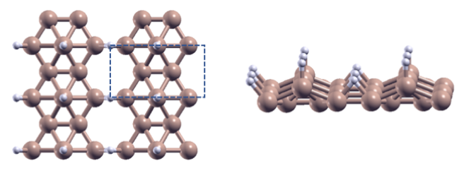
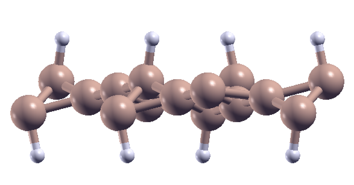
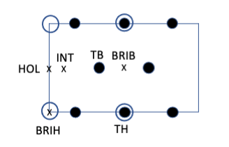
The structure of the two polymorphs Rect–2H and H is shown in Figs. (1) and (2), respectively. These configurations can be considered as derived from the and borophene structures, respectively.Gozar We computed the He-substrate interaction for a selected set of nonequivalent sites in the primitive surface unit cell (see Figs. (3) and (4) ).
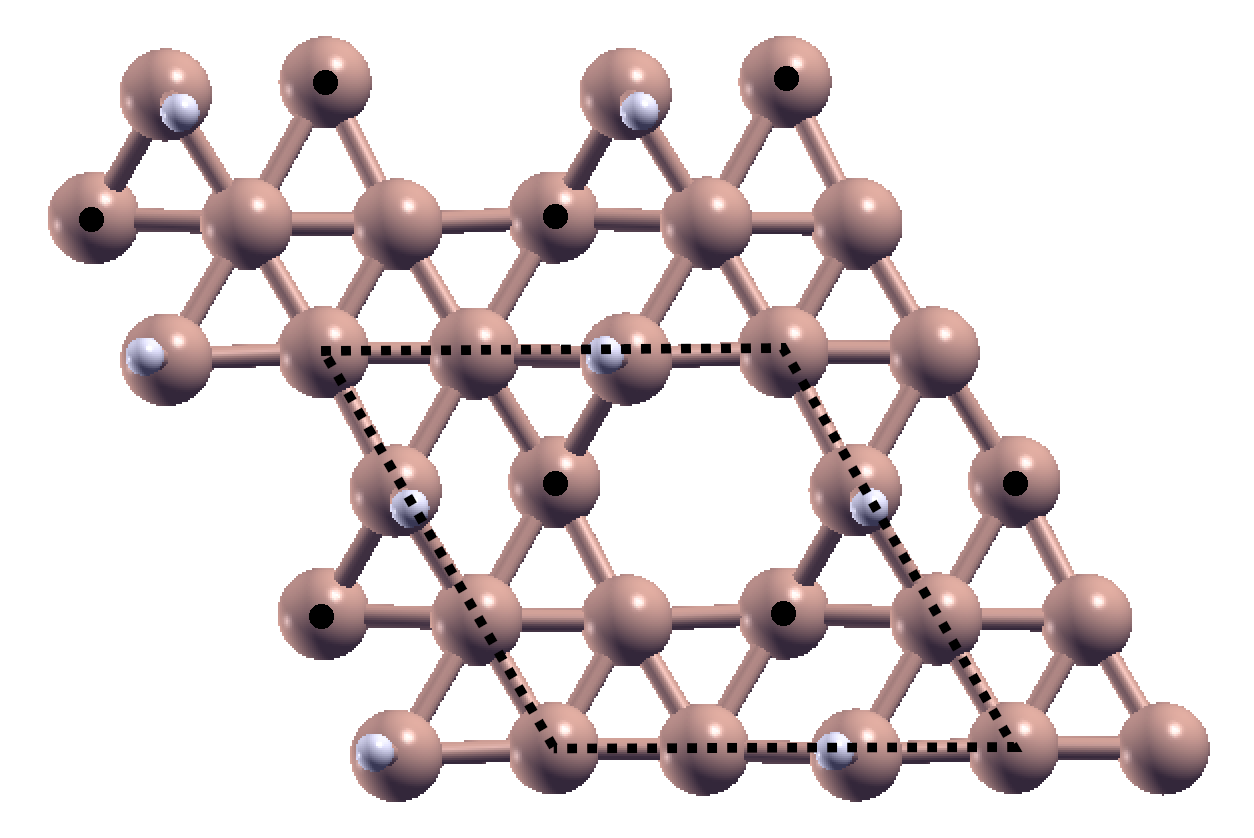
For Rect–2H we chose the following points: HOL (hollow site), TB (site on top of B atom), TH (site on top of H atom), BRIH (bridge site on top of a H atom between two B atoms); INT (intermediate site between HOL and TB); BRIB (bridge site between two B atoms). The chosen sites are shown in Fig.(3); we have considered the adsorption of He on both the upper and lower surface.
For each chosen point of 4He we computed the energy as function of the coordinate finding the lowest value. Our most relevant numerical results for the adsorption of He on the Rect-2H borophane substrate are summarized in Tables I and II.
As can be seen the most stable adsorption site (for both the upper and lower surface) for He on Rect-2H borophane is the HOL site. The least favored sites, characterized by the highest-energy, are instead the TH site (for the upper surface) and the BRIB site (for the lower surface). The minimum intersite barriers and , reported in Table II, are given by the energy barriers between two adsorption sites for displacements constrained to the and directions, respectively, while optimizing the coordinate. They are given by the binding energy differences between BRIB and HOL sites along and BRIH and HOL sites along . Clearly is much larger than the minimum energy barrier and for the upper surface =47 K is equal to the value for a graphene substrate.moroni21
| site | (K) (upper surface) | (K) (lower surface) |
|---|---|---|
| HOL | -268 (-344) | -245 |
| INT | -244 (-325) | -224 |
| BRIH | -221 (-291) | -212 |
| TB | -142 (-175) | -170 |
| BRIB | -133 (-162) | -163 |
| TH | -123 (-136) | -180 |
| (K) | (K) | (K) | ||
|---|---|---|---|---|
| upper surface | -268 | 3.4 | 135 | 47 |
| lower surface | -245 | -3.2 | 82 | 33 |
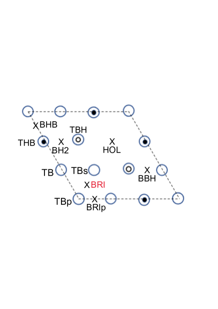
For H we chose the points labelled in Fig. (4). The most-favored adsorption site, denoted by the label BRI (in red), corresponds to the midpoint between two undecorated B atoms, while the least-favored one, denoted by the label THB in Fig.(4), is on top of a H atom forming a bond with a B atom below it. The main results are listed in Table III. In this structure the minimum intersite barrier is found to be 86 K.
If we compare the energetic data characterizing the adsorption of He on the H and rect-2H substrates with those found in the case of adsorption of He on graphene,reatto_2013 ; moroni21 one can see that the binding energy in the favored adsorption site (HOL on graphene and rect-2H and BRI on H) is similar (-298 K in He-graphene); however, both the corrugation and its anisotropy turn out to be more pronounced in borophane structures than in graphene, where the maximum corrugation (50K) and minimum intersite barrier (47K) are relatively small and comparable.
| site | (K) |
|---|---|
| BRI | -269 |
| TBs | -263 |
| TBp | -230 |
| BBH | -224 |
| BRIp | -218 |
| TB | -187 |
| HOL | -183 |
| TBH | -174 |
| BHB | -172 |
| BH2 | -153 |
| THB | -151 |
In order to corroborate our basic results, we have repeated the calculations by adopting a different, vdW-corrected DFT functional, namely the DFT-D2 functional (semiempirical in character).Grimme06 Although with DFT-D2 the values for the energies are systematically more negative than those calculated with the rVV10 functional (see Table I), so the predicted He-borophane bonding is stronger, nonetheless the energetic ordering is preserved, and thus we do not expect a potential energy surface much different from that obtained using rVV10. In any case, from previous work,Sabatini ; psil15 ; psil16 the rVV10 functional turns out to be more accurate than DFT-D2 for this kind of application. For this reason we decided to only consider the rVV10 functional to generate the adsorption potential for He on borophane.
Besides the lowest-energy configurations for a given investigated site, we have also computed the dependence upon the normal coordinate of the He-substrate interaction potentials. We fitted the calculated points, for each site, using the results of a 8-parameter curve fitting with the form whose parameters are given in Table 4.
| Rect-2H (upper surface): | ||||||||
|---|---|---|---|---|---|---|---|---|
| HOL | ||||||||
| BRIH | ||||||||
| BRIB | ||||||||
| TH | ||||||||
| TB | ||||||||
| INT | ||||||||
| Rect-2H (lower surface): | ||||||||
| HOL | ||||||||
| BRIH | ||||||||
| BRIB | ||||||||
| TH | ||||||||
| TB | ||||||||
| INT | ||||||||
In order to perform a many-body computation one needs the full adsorption potential . To this end we approximate the potential by using a truncated Fourier expansion over the vectors of the two-dimensional reciprocal lattice associated with the lattice of the substrate:
| (1) |
where the () are the first five stars of two-dimensional reciprocal lattice vectors, ( and , ).
The Fourier components can be easily obtained, for a given value of , from the calculated values of , as defined above.nota
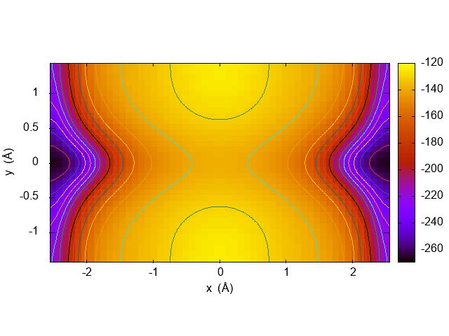
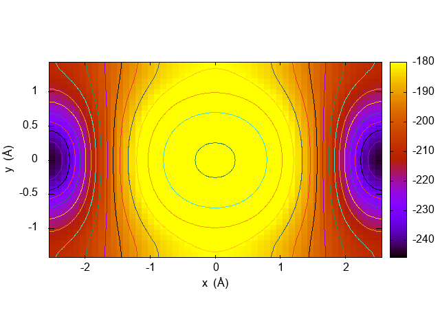
In Fig.(5) and Fig.(6) we show, by means of equal energy contours, the potential energy map in the unit cell for the upper and lower surface of the Rect-2H borophane monolayer, corresponding to the minimum value of the potential for each point . These figures clearly show the high ridge of the adsorption potential in the center of the unit cell, a ridge which divides the regions of the preferential adsorption sites, forming a kind of channels for easy motion of the adsorbed atoms.
III Quantum Monte Carlo simulations
We use the path integral Monte Carlo methodpimc in the worm algorithmworm implementation to calculate unbiased thermal averages in the grand canonical ensemble for an assembly of 4He atoms adsorbed on the upper surface of Rect-2H borophane (hereafter BPH-rect), with periodic boundary conditions in the directions parallel to the substrate. The size of the simulation cell is along and along . The interaction between He and BPH-rect is the upper-surface rVV10 potential of Sec. II,dft-d2 and the pairwise He-He interaction is the HFDHE2 Aziz potential.aziz In case BTP-rect could be produced as free standing sheet also the lower surface should be relevant. A few results for the lower surface are reported in the Supplemental Material.suppmat The technical details of the simulation are the same as in Ref. moroni21, .
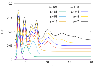
The growth of the film proceeds by successive filling of adsorption layers. Individual layers are well characterized, at least at low coverage, by well resolved peaks of the lateral average of the He density as a function of , see Fig. (7).
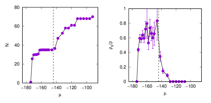
Figure (8) shows the evolution of the coverage and of the superfluid fraction as the chemical potential increases, with the temperature kept fixed at K. Here the coverage is defined through the number of 4He atoms in the simulation cell. The main jumps or shoulders in , marked by changes in color, indicate promotion to the next layer (except red to blue, see below). Flat portions of the curve correspond to crystalline ordering. The superfluid density is calculated with the winding number estimator.pimc The superfluid fraction shown in Fig. (8) is defined as , where is the total density of 4He minus the density of the crystalline layers not involved in the superfluid flow. In detail, we subtract atoms for layer 2 and for layer 5 and above.
When the superfluid fraction is anisotropic in the plane, we show separately the contributions coming from the and components of the winding number.pimc

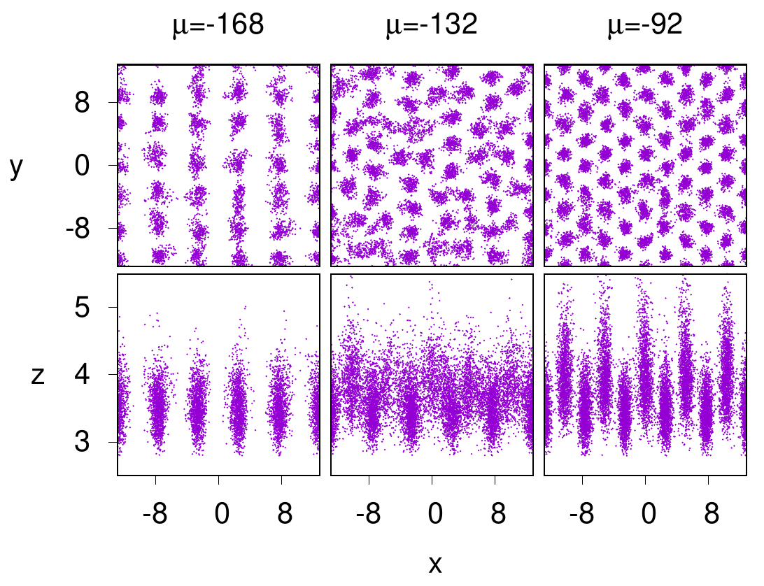
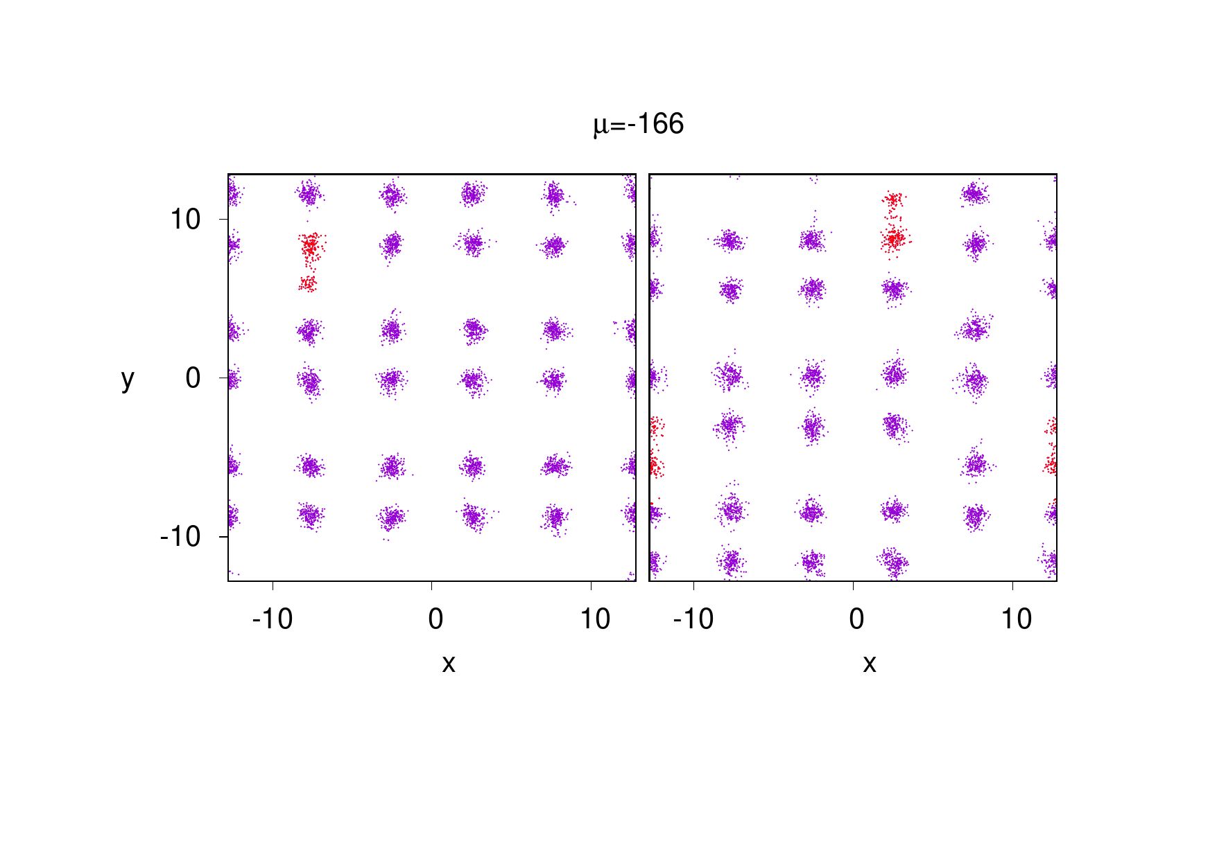
For representative values of the coverage, Figs. (9) and (10) show snapshots of the path integral configurations, which encode information on the localization (or lack thereof) of the 4He atoms. We now discuss the properties of individual adsorption layers.
Layer 1. For coverages up to , each 4He atom is pinned to one of the absorption sites (HOL), see leftmost panels in Fig. (9). At complete filling of the first layer we have an ordered state in registry with the substrate. It can be noticed that the distance 2.855Åbetween neighboring 4He atoms along the direction corresponds to the interatomic distance in solid 4He at a very high pressure. Here this large compression is due to the very strong adsorption potential. When the filling is incomplete, particle can hop between sites in the direction and, in principle, sustain a superfluid flow. However, the intersite minimum density along is as small as 1/150 the peak value, so that a very low critical temperature is expected. Indeed, we find no superfluidity down to the lowest temperature studied, =0.1 K. For incomplete fillings, the vacant adsorption sites tend to align along the direction, in order to minimize the energy contribution from the attractive tail of the interaction between atoms apart.suppmat
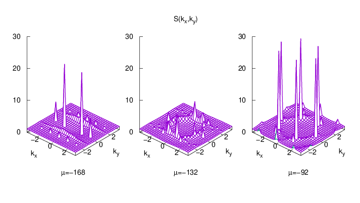
Layer 2. The second layer is a fluid distributed in separated channels along the direction, alternate to the HOL sites, as shown by the panels of Fig. (9) corresponding to . Note in particular that the path of nearest neighbor particles are rather delocalized along and often overlap. Further support to the assignemt to a fluid phase comes from the static structure factor, which features characteristic ridges.moroni21 ; suppmat Each channel contains up to 7 4He atoms, i.e. the interatomic distance along is dictated by the He-He repulsion rather than by the 9-fold periodicity of both the substrate corrugation and the first layer density profile. The superfluid fraction is non zero, in the finite samples simulated. It is entirely due to intra-channel exchanges, because the component of the winding number is zero. It can be noticed that the superfluid fraction in this second layer has a maximum as function of chemical potential and drops as approaches the value for promotion to the next layer. This drop can be considered as a precursor of the crystallization of the particles of the second layer when the third layer is formed. A similar situation has been studied through PIMC simulations of strongly interacting 2D bosons confined to 1D channels by an external periodic potential modulated along one direction.yao Below quantum degeneracy, a 2D-1D dimensional crossover is observed as the amplitude of the external potential increases at fixed particle density. The coupling between the 1D channels is further characterized as either coherent or incoherentyao when the transverse superfluid fraction has a finite or vanishing value, respectively. Based on this criterion, the 4He atoms in the second layer belong to the 1D incoherent regime.
Layer 3. The promotion to the third layer is very sharp, with the sudden appearance of a 75 lattice with coordinates alternate to the second layer channels, i.e. back on top of the HOL sites (panels at in Fig. (9)). Concurrently, this lattice pushes the density of the second layer closer to the substrate, as shown by the shift of the second peak in Fig. (7), and strongly localizes the paths of the second layer in the direction; thus the second layer crystallizes as well and the superfluid density drops to zero. The pale blue portion of the curve is flat, except for a jump between and ; such a jump corresponds to a switch between the 75 lattice to an 5 arrangement, both in the third and in the second layer. In the thermodynamic limit, the second and third layers presumably evolve as matched compressible crystals, incommensurate to the corrugation of the substrate in the direction.
Layer 4. The alternation in the direction with the atoms of the previous layer continues in the fourth layer, but it is much less sharp, as it is the separation among the paths of individual atoms, see Fig. (9) for . Despite the increased delocalization, the system presents neither liquid-like ridges in the structure factor, nor superfluid flow. We therefore assign also the fourth layer to a crystal phase. The density is lower than in the third layer at completion: in the example shown, there are 34 atoms in the fourth layer. At this stage, layers 1 and 2 and layers 3 and 4 are best seen as two buckled crystals, with only the sublattice of layer 1 being commensurate to the substrate in the direction. As the coverage increases, the buckled crystal formed by layers 3 and 4 evolves through different structures, all characterized by the presence of defects. Whether this is a constraint imposed by the geometry of the simulation cell, unable to accommodate the preferred crystalline structure(s), or to intrinsic stability of the defects themselves in the thermodynamic limit is left to further investigation.
Layer 5. In discussing the fifth layer we deviate from the code of one color per layer. The initial coverage of layer 5 is illustrated in red in Figs. (7,8,10). It is a liquid modulated along the direction, although more weakly than all the structures previously described, and very delocalized in the direction. The superfluid fraction in this layer is non-zero not only in the direction but also in the direction and in this initial coverage of layer 5 is strongly anisotropic with a ratio of the two conponents that is as large as three. When the coverage increases (blue color, ), the fluid channels along the directions overlap significantly, and the superfluid fraction becomes isotropic despite the persistence of a residual modulation along , particularly closer to the substrate. From the point of view of superfluidity this layer 5 offers an interesting example of crossover between two regimes: at small coverage of this layer the superfluidity is strongly anisotropic reflecting the ridges of the adsorption potential and this regime merges into an isotropic one in the plane as the coverage of this layer moves toward completion.
Layers 6 and 7. For higher coverages the modulation along fades away, and the distinction between layers gets blurred. Promotion to the sixth layer onwards does not induce crystallization of layers beneath, and the film evolves smoothly towards the bulk system.
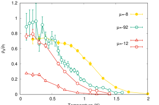
The dependence of on the temperature is illustrated in Fig. (11). We have not attempted to determine the critical temperature by finite size scaling. Qualitatively, we see that superfluidity persists at higher temperatures for a nearly homogeneous density () than for strongly modulated ones ( and ). The superfluid fraction tends to flatten as function of temperature below 0.2-0.4 K depending on coverage so that the results at the lowest of the present computations can be considered as representative of the ground state of the system. In a uniform superfluid the superfluid fraction should be unity at K but this is not the case for a non-uniform superfluid as shown by Leggettleggett and the larger is the density modulation the stronger is the depression of the superfluid fraction. Such reduction has been experimentally verified with cold bosons atoms in an optical latticetao and it has been predicted theoretically in the case of 4He adsorbed on fluorographenemoroni21 and in a Bose-Einstein condensate in an optical lattice.ar In the present study of 4He on BPH-rect we find a reduction of the superfluid fraction in the adsorbed layers that show superfluidity, i.e. in the second layer, in the fifth and above even at the lowest of our computations. The strongest reduction is found in the superfluid fraction in the direction, i.e. across channels, in the fifth layer at coverage with anisotropic superfluidity. In fact this is the case with the largest density modulation as shown in the Supplemental Material.suppmat We use the ratio of the minimum to the maximum density as a measure of the amplitude of the density modulation. In the direction is 0.47 in the first layer at and it is essentially zero in the direction. In the fifth layer at we find in the direction along the channels and in the direction, indeed the case with the strongest reduction of the superfluid fraction. Also in the case of isotropic superfluidity we find some reduction of the superfluid fraction from unity as can be seen in Fig. (11) for . This presumably is due to a remnant density modulation in the layers rather close to the substrate.


IV Summary and conclusions
In this paper we have investigated if borophane is an attractive substrate for study of adsorbed 4He in the search of new superfluid phases in restricted geometry. We have investigated the adsorption properties of 4He atoms on two allotropes of borophane, H and Rect-2H, by using ab initio DFT. The adsorption energy of a He atom has about the same value for these two allotropes of borophane and it is similar to that on graphene/graphite. For both allotropes of borophane the corrugation of the adsorption potential is much stronger than on graphene/graphite and it has a complex shape reflecting the presence of the chemisorbed Hydrogens. In the case of H borophane the lowest energy barrier for moving from one adsorption site to a neighboring one is about 80% larger than the barrier in the case of graphene/graphite. The maximum corrugation of the adsorption potential, defined as the difference between its minimum and its maximum value in the the first adsorption layer, is more than 100 K, to be compared to about 3 K in the case of graphene. On the basis of such features of the adsorption potential and comparison with the case of graphene/graphite we expect that the 4He atoms will be localized around the adsorption sites. Such adsorption sites on H form a triangular lattice so that at low temperature the preferred state for the first adsorbed layer should be a registered triangular state similar to the well known phase on graphite/graphene. We have not pursued here the study of 4He on H borophane at higher coverages.
The adsorption potential of He on Rect-2H borophane is characterized by parallel deep channels with large energy barriers (of order of 135 K) between neighboring channels and much smaller barriers (of order of 47 K) along a channel. As a consequence the first few layers of adsorbed 4He have a pronounced one dimensional character. Our results show that this substrate offers a unique platform to study degenerate bosons and superfluidity in different dimensions.
In the first adsorbed layer quantum degeneracy is present in only one direction, along a channel, but presumably superfluidity might be present only at temperatures well below those of our simulations. In the second layer quantum degeneracy shows up as a one-dimensional superfluid response on the length scale of our simulated system, this represents a 1-D incoherent regime because particles in neighboring channels are not phase correlated. In the fifth layer we find two regimes. At low coverage the system is a strongly anisotropic 2-D superfluid, the superfluid fraction in the direction perpendicular to the channels is about one third of the fraction along the channels. This anisotropy diminishes as the coverage of the layer increases and at a critical value the 2-D superfluidity becomes isotropic in the plane. Starting from the sixth layer the system evolves towards a bulk 3-D superfluid.
The present study suggests a number of possible extensions. For instance, in the case of Rect-2H borophane a systematic size scaling study will give information on criticality in isotropic versus anisotropic superfluidity in 2D in the fifth adsorbed layer or, in the case of 1-D incoherent superfluidity of the second layer, it will allow a comparison with the Luttinger fluid paradigm,haldane ; giamarchi a 1-D model from which the present system deviates because the bosons move in a periodic potential along a channel and because rows of atoms in neighboring channels, even if phase uncorrelated, are spatially correlated. Also a study of 4He on H borophane at coverage beyond the here predicted registered triangular phase should be of interest. The study of the fermion 3He adsorbed on graphite has been a fruitful field of research.greywall_1990_1991 The present results for the interrelation between quantum degeneracy and dimensionality in the case the boson 4He on Rect-2H borophane suggest the interest of a similar study for 3He.
References
- (1) C. Hou, G. Tai, Z. Wu and J. Hao, ChemPlusChem 85, 2186 (2020).
- (2) A. J. Mannix, Z. Zhang, N. P. Guisinger, B. I. Yakobson, M. C. Hersam, Nat. Nanotechnol. 13, 444 (2018).
- (3) Q. Li et al., Science 371, 1143 (2021).
- (4) C. Hou, G. Tai, J. Hao, L. Sheng, B. Liu, and Z. Wu, Angew. Chem. 59, 10819 (2020).
- (5) P. A. Crowell and J. D. Reppy, Phys. Rev. B 53, 2701 (1996).
- (6) D. S. Greywall, Phys. Rev. A 41, 1842 (1990); D. S. Greywall and P. A. Bush, Phys. Rev. Lett. 67, 3535 (1991).
- (7) P. A. Crowell, F. W. Van Keuls and J. D. Reppy, Phys. Rev. B 55, 12620 (1997).
- (8) L. W. Bruch, M. W. Cole and E. Zaremba, Physical Adsorption )Mineola, NY: Dover, 2007).
- (9) L. Reatto, D. E. Galli, M. Nava and M. W. Cole, J. Phys.: Condens. Matter 25, 443001 (2013).
- (10) S. Moroni, F. Ancilotto, P. L. Silvestrelli and L. Reatto, Phys. Rev. B 103, 174514 (2021). P.L. Silvestrelli, M. Nava, F. Ancilotto and L. Reatto, J. Low Temp. Phys. 196, 42 (2019).
- (11) M. Nava, D. E. Galli, M. W. Cole and L. Reatto, J. Low Temp. Phys. 171, 699 (2013).
- (12) For a review, L. I. Yukalov, Laser Physics 19, 1 (2009).
- (13) P. Giannozzi, S. Baroni, N. Bonini, M. Calandra, R. Car, C. Cavazzoni, D. Ceresoli, G. L. Chiarotti, M. Cococcioni, I. Dabo, A. Dal Corso, S. De Gironcoli, S. Fabris, G. Fratesi, R. Gebauer, U. Gerstmann, C. Gougoussis, A. Kokalj, M. Lazzeri, L. Martin–Samos, N. Marzari, F. Mauri, R. Mazzarello, S. Paolini, A. Pasquarello, L. Paulatto, C. Sbraccia, S. Scandolo, G. Sclauzero, A. P. Seitsonen, A. Smogunov, P. Umari, and R. M. Wentzcovitch, J.Phys.: Condens. Matter 21, 395502 (2009).
- (14) R. Sabatini, T. Gorni, S. de Gironcoli, Phys. Rev. B 87, 041108(R) (2013).
- (15) O. A. Vydrov, T. Van Voorhis, J. Chem. Phys. 133, 244103 (2010).
- (16) P. L. Silvestrelli, A. Ambrosetti, Phys. Rev. B 91, 195405 (2015).
- (17) P. L. Silvestrelli, A. Ambrosetti, J. Low. Temp. Phys. 185, 183 (2016).
- (18) A. Gozar, I. Bozovic, R. Wu., Nano Today 50, 101856 (2023).
- (19) S. Grimme, J. Comp. Chem. 27, 1787 (2006).
- (20) Three dimensional tabulations of the He-substrate potentials are available upon request from one of the authors (F.A.).
- (21) D.M.Ceperley, Rev. Mod. Phys 67, 279 (1995).
- (22) M. Boninsegni, N. V. Prokof’ev, B. V. Svistunov, Phys. Rev. E 74, 036701 (2006).
- (23) We have verified that the DFT-D2 potential gives qualitatively similar results.
- (24) R. A. Aziz, V. P. S. Nain, J. S. Carley, W. L. Taylor, and G. T. Conville, J. Chem. Phys. 70, 4330 (1979).
- (25) See Supplemental Material at http://link for results on the vacancy alignment in layer 1, the structure factor in layers 2 and 3, the density modulation in layers 2 and 5, and adsorption on the lower surface of PBH.
- (26) H. Yao, L. Pizzino, T. Giamarchi, SciPost Phys. 15, 050 (2023).
- (27) A.J. Leggett, Phys. Rev. Lett. 25, 1543 (1970); A.J Leggett, J. Stat. Phys. 93, 927 (1998).
- (28) J. Tao, M. Zhao and I.B. Spielman, Phys. Rev. Lett. 131, 163401 (2023).
- (29) F. Ancilotto and L. Reatto, Phys. Rev. A 110, 013302 (2024).
- (30) F. D. M. Haldane, Phys. Rev. Lett. 47, 1840 (1981).
- (31) T. Giamarchi, Quantum Physics in One Dimension (Oxford University Press, 2004).
- (32) M. Nava, D. E. Galli, M. W. Cole, L. Reatto, Phys. Rev. B 86, 174509 (2012).
- (33) J. Neugebauer, and M. Scheffler, Surf. Sci. 287/288, 572 (1993).
- (34) L. Bengtsson, Phys. Rev. B 59, 12301 (1999).
- (35) B. Meyer, and D. Vanderbilt, Phys. Rev. B 63, 205426 (2001).
- (36) J. H. J. Ostrowski, and J. D. Eaves, J. Phys. Chem. B 118, 530 (2014).
Supplemental Material
This Supplemental Material contains
(i) examples of vacancy alignment in the first adsorption layer;
(ii) the static structure factor with two adsorption layers, with a fluid component,
and three layers, entirely solid;
(iii) density profiles in and for the second and the fifth
adsorption layer;
(iv) results for the first two adsorption layers on the lower surface;
Energies are in K and distances in Å.
Vacancy alignment
In the first layer atoms are pinned one-on-one to adsorption sites. For incomplete filling, vacant sites tend to align along the direction, as shown by two examples in Fig. 12.
Static structure factor
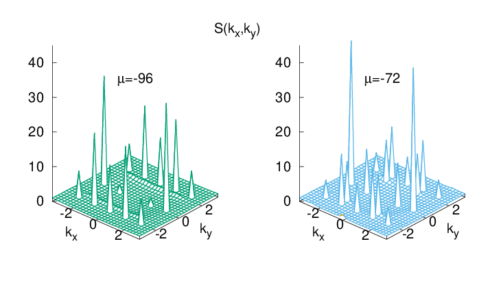
The assignment to a solid or fluid phase in a given layer is supported by the structure factor (see Fig. 13). For two layers, alongside various Bragg peaks corresponding to the period of the substrate, there is a ridge at signalling fluid behavior along the direction; in the fully solid structure which develops after promotion to the third layer, such a ridge gives way to additional Bragg peaks corresponding to a period dictated by the He-He hard core.
Density profiles
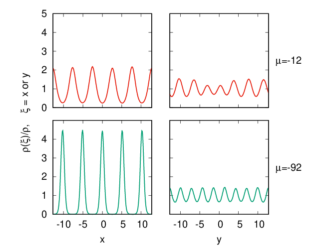
In Fig. 14 we show the density modulations in the and directions of the second layer at and the fifth layer at . Here stands for either or , is the average density, and is the density averaged over the two directions other than . The non-equivalence of the minima and maxima in the fifth layer (top panels), particularly evident in the direction, is due to disorder present in the (localized) 4He atoms in the underlying fourth layer.
Adsorption on the lower surface
The substrate-He potential for the lower surface of BPH-rect has smaller barriers between adsorption sites (see Table II in the main text). The 4He atoms in the first layer are not pinned one-on-one to the sites and sustain superfluid flow. Superfluidity persists up to slightly beyond completion of the first layer (see Fig. 15). As the coverage of the second layer increases, a buckled exagonal crystal develops, incommensurate to the substrate.
This is illustrated by snapshots of the path integral configurations in Fig. 16 and by the structure factor in Fig. 17.