Measurement-based uncomputation of
quantum circuits for modular arithmetic
Abstract
Measurement-based uncomputation (MBU) is a technique used to perform probabilistic uncomputation of quantum circuits. We formalize this technique for the case of single-qubit registers, and we show applications to modular arithmetic. First, we present formal statements for several variations of quantum circuits performing non-modular addition: controlled addition, addition by a constant, and controlled addition by a constant. We do the same for subtraction and comparison circuits. This addresses gaps in the current literature, where some of these variants were previously unexplored. Then, we shift our attention to modular arithmetic, where again we present formal statements for modular addition, controlled modular addition, modular addition by a constant, and controlled modular addition by a constant, using different kinds of plain adders and combinations thereof. We introduce and prove a “MBU lemma” in the context of single-qubit registers, which we apply to all aforementioned modular arithmetic circuits. Using MBU, we reduce the Toffoli count and depth by to for modular adders based on the architecture of [VBE96], and by almost for modular adders based on the architecture of [Bea02]. Our results have the potential to improve other circuits for modular arithmetic, such as modular multiplication and modular exponentiation, and can find applications in quantum cryptanalysis.
1 Introduction
Consider a quantum circuit computing a Boolean function between bit strings. When is invertible (meaning that is injective and ) we say that computes in-place if it performs the mapping
| (1) |
for any bit string , where we use the subscripts to denote the number of qubits in a quantum register. An in-place implementation is not always possible. In the most general case, one needs to compute out-of-place, meaning that the circuit realises the following mapping
| (2) |
A realistic implementation of the above gate will, in principle, involve a number of auxiliary qubits which get mapped in a garbage state as follows:
| (3) |
The auxiliary qubits are entangled with the other registers and must be uncomputed, i.e. restored to their original value, in order to get a reversible out-of-place implementation of . Such uncomputation can be achieved in several ways. A first solution, due to [Ben73], simply prescribes copying the output into an auxiliary -qubit register via a set of CNOT gates and then apply . Therefore, one can implement as in figure 1.
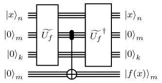
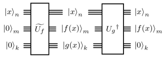
This strategy doubles the resource cost of the reversible computation of , also requiring more ancillary qubits. Alternatively, one could look for an out-of-place implementation of the garbage function , seeing as a function of and . When this unitary is available, one can implement as in figure 2.
In principle, invoking the garbage circuit can be quite resource intensive. Therefore, it is necessary to develop techniques to optimize the synthesis of quantum circuits and their uncomputation.
Arithmetic Circuits.
Effective implementations of binary arithmetic are fundamental to many quantum algorithms, such as quantum algorithms for factoring [Sho94, GE21] and discrete logarithm [Eke18], quantum walks [Chi02], and for algorithms that construct oracles for Grover’s search and quantum phase estimation, e.g. [Ber+19, Dor+22, Agg+17]. Arithmetic operations like (modular) addition, subtraction, and comparison (by a constant) have been extensively studied, resulting in numerous implementation strategies, each with its own tradeoffs. Many circuits for arithmetic are based on the plain addition circuit defined by the operation for two -qubit quantum registers. Other primitives can be derived by composing these circuits for addition. However, there are often more efficient ways to build arithmetic primitives. Broadly, these quantum circuits are designed for both quantum-quantum arithmetic functions, i.e., circuits of the form , and quantum-classical arithmetic functions, i.e., circuits of the form .
In the computation of our function , intermediate values may need to be appropriately uncomputed. For example, any ripple carry addition algorithm, analogously to the schoolbook addition method, requires computing the carry bitwise starting from the least significant bits of the two addends.
However, this process leaves carry bits in memory, which need to be uncomputed from the rest of the registers to ensure the correctness of the computation. Efficient quantum arithmetic circuits are pivotal for advancing quantum computing, underpinning numerous key algorithms. This also involves finding cheaper ways of performing uncomputation on qubits storing garbage/intermediate computations.
1.1 Main results
In this work, we improve quantum circuits for modular arithmetic using measurement-based uncomputation, specifically focusing on quantum modular adders. In section 2, we begin by formalizing previously known circuits for addition and defining in a theorem the resources required for their implementation. For all the adders we consider [Cuc+04, VBE96, Dra00, Gid18], we also cover the possible cases for (controlled) addition, subtraction and comparison (by a constant). While these constructions can be easily derived, we could not find records of many of them in previous literature, e.g., (controlled) comparator by a constant, controlled modular addition, etc. We offer a modular and composable framework to construct these arithmetic circuits from other known arithmetic primitives. We also show a construction for a controlled adder using just a single ancilla by modifying the CDKPM adder (theorem 2.12). In section 3, we consider various tradeoffs for combining the results presented in the previous section to form a quantum circuit that performs a (controlled) modular addition (by a constant). In particular, we show how two different adder architectures (the CDKPM adder [Cuc+04] and Gidney adder [Gid18]) can be combined, leading to better space-time tradeoffs compared to using either adder individually within the modular adder architecture (see theorem 3.6). These tradeoffs are particularly important when running quantum algorithms in early error-corrected settings. In section 4, we discuss the proof of the measurement-based uncomputation lemma, which we present below. This technique was already known in the literature [Gid18, KSS21, Gid19], but to the best of our knowledge, it has not been formalized as a plug-and-play result. While MBU can be generalized to uncomputation of multi-qubit registers, for modular arithmetic we can use the following lemma.
Lemma (Measurement-based uncomputation lemma).
Let be a function, and let be a self-adjoint -qubit unitary that maps . There is an algorithm performing the mapping using , gates, and gate with probability. It also involves one single-qubit computational basis measurement and a single gate.
Applying the MBU lemma leads to gate costs expressed “in expectation”. The expected value is calculated based on a Bernoulli distribution with a probability . This is because, for any quantum state , if , when the last register is measured in the basis, there is an equal probability of obtaining a or state. The remainder of section 4 is dedicated to deriving formal statements for modular addition circuits optimized by MBU. While table 1 presents our results for modular addition (section 4.1), we also share resource counts for controlled modular addition (section 4.2), modular addition by a constant (section 4.3), and controlled modular addition by a constant (section 4.4). For example, for the controlled modular adder derived from [Cuc+04], MBU can reduce the (Toffoli) count by gates in expectation (compare proposition 3.4 with proposition 3.10). The minimum number of gates is achieved by proposition 3.11 using ancilla qubits. For modular addition by a constant, MBU reduces the count by gates in expectation (compare proposition 3.15 with theorem 4.11), leading to a improvement on the original circuit. We obtain similar improvements for controlled modular addition by a constant. We also show a way to perform a double-sided comparison (theorem 4.13), i.e. to see if a given register’s value is contained within two other register’s values. This circuit is a prime candidate for MBU, leading to a nearly reduction in the cost of the circuit.
Our work has the potential to improve quantum circuits for modular multiplication, modular exponentiation, and quantum circuits for cryptographic attacks [Wan+24, VBE96, Wan+24a]. We leave this research for future work. The interested reader can access 111https://github.com/AdithyaSireesh/mbu-arithmetic the code for symbolic computation of some of the statements presented in this work.
1.2 Related works
This section reviews recent progress in quantum circuits for modular arithmetic, with a focus on optimizing size and depth. Then, we turn our attention to previous applications of measurement-based uncomputation. Early proposals for quantum addition [Cuc+04, VBE96, Dra+04], some of which are employed in fault-tolerant algorithms with state-of-the-art resource estimates [GE21, Lit23, Gou+23], were inspired by classical circuits for addition, with an emphasis on minimizing the count and/or the (Toffoli) count, and the number of ancilla qubits. Subsequent approaches have explored more quantum-specific methods of performing arithmetic [Zal06, Dra00, Bea02, Yua+23]. A nice quantum-specific way to perform a modular addition into a quantum register was developed by Zalka [Zal06]. It involves only a single non-modular addition (with modulus ) as long as is prepared in a coset state: . The overhead here is that the size of the padding (i.e. the value of of extra qubits required) for the coset state grows logarithmically in the number of additions that are to be performed (See [Gid19] for more details). All these arithmetic circuits listed previously (and many others) serve as building blocks for more complex operations such as modular addition, multiplication, and exponentiation, to name a few. Another survey on quantum adders can be found in [Tak09]. The interested reader is encouraged to read [Wan+24a] for a comprehensive literature review.
Measurement-Based Uncomputation (MBU).
Measurement-based uncomputation (MBU) was developed to efficiently address the challenge of uncomputing boolean functions. MBU is a technique used to perform uncomputation in a probabilistic manner [Gid18]. This technique involves measuring the qubits to be uncomputed on the basis. Depending on the outcome of the measurement, either the uncomputation circuit is executed, or it is determined that the uncomputation has already been completed, thereby reducing the overall quantum resource requirements.
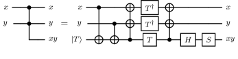
MBU has been employed in several cases [Gid18, KSS21, Gid19, Gid19b] to improve the resource counts of uncomputation. In particular, Gidney applied this strategy to addition circuits in [Gid18]. Starting from a Ripple Carry Addition (RCA) algorithm (see section 2 for details), they manage to reduce the gate cost by replacing every gate with a temporary logical- gate (equivalent to a gate). While a gate performs the mapping , the logical- gate uses an ancilla qubit to execute the gate as follows:
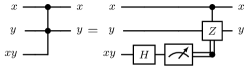
Since the gates come in pairs (the gates used in the RCA computation must also be uncomputed), MBU is used to avoid performing a gate for the uncomputation, replacing it with an basis measurement followed by a classically controlled gate. In [Gid19], MBU is used to construct the coset state more effectively. In the QROM lookup circuits introduced in [Bab+18, Gid19b], MBU is used to construct a highly efficient unlookup (uncomputation of lookup) operation. For an address register , a lookup table performs the operation
| (4) |
where is the lookup value associated with address . An address register of size qubits corresponds to a lookup table of elements, making the cost of performing a lookup Toffolis. After has been used in the computation, it must be uncomputed. Naively performing the uncomputation would cost the same as the lookup. However, by combining unary encoding with MBU, it is possible to reduce the cost of the uncomputation to just [Bab+18, Gid19b] gates.
Other works study the more general problem of reversibly computing a chain of functions through the use of pebbling games [Ben89]. Pebbling games offer a way to perform these computations reversibly and find effective ways of studying space-time tradeoffs of various strategies to uncompute intermediate results. In the case of chains of unitaries , spooky pebble games were introduced by Gidney [Gid19a], which allowed basis quantum measurements as an additional operation in pebbling games. The measurements may result in a phase applied to the states in the superposition, which is then tracked and corrected at a later time in the computation.
1.3 Notation and convention
We assume basic knowledge of quantum computing; we refer the interested reader to [NC11]. As in [Cuc+04], we denote the quantum registers by capital letters , etc. Each register is encoded with several qubits; we denote by the -th qubit of register . Each qubit can be understood as a memory location; if not differently stated, we will assume that in qubit is initially stored the value . We represent the state of a qubit register as . In principle, applying a quantum gate to a given register affects the values stored in its qubit; we denote by the storing of value in the -th component of register as the result of a certain quantum circuit. Where necessary, we put the number of qubits in a register as a subscript following the ket representing the register’s state, e.g. for an -qubit register. For an bit string we shall often equate it with the decimal number encoded in binary by . We denote with the bit string encoding the number in the ’s complement notation (see remark A.4 in the appendix). For a number , denotes the Hamming weight of the binary representation of . The interested reader is referred to [Von93] or [HH10] and appendix A for further details on bit strings operations.
Quantum computing.
We recall the definition of the following single-qubit gates.
, , , .
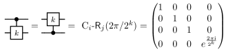
We denote by the rotation by of qubit controlled by qubit (See figure 3). We can eventually use register names indexed by its qubits: e.g. performs a controlled rotation between the -th qubit in the register and targets the -th qubits in the register . We define the function to be if is true, otherwise is . In the case of a based adder by a constant, we use to denote a classically controlled set of rotation gates that need to be applied in order to perform the required addition in the phase.
Let . The state obtained after applying the quantum Fourier transform (see e.g. [NC11]) to the state is given by
We denote by the quantum Fourier transform acting on a qubits register and by its inverse.
Let be a quantum circuit composed of gates from a gateset . Define the gate count for . We represent the gate counts of as
Remark 1.1 (Circuit size of QFT [NC11]).
A has a circuit size of
Boolean arithmetic.
In this paragraph, we will review some basic definitions of bit string arithmetic. Denote by a -bit string i.e. a string of binary numbers. Further facts about the bit string representation of integers are reported in appendix A. We consider the following four operations on the set of -bits string.
Definition 1.2 (Bit string addition).
We call bit string addition the binary operator
defined bit-wise by where the bit , called -th carry, is defined recursively by
| (5) |
The function maj is a logic gate called majority, which gives whenever at least two of the three entries are different than .
Definition 1.3 (Bit string ’s complement).
We call ’s complement the operator defined bit-wise by as
Definition 1.4 (Bit string ’s complement).
We call ’s complement the operator defined as , where denotes the bits string as
Definition 1.5 (Bit string subtraction).
We call bit string subtraction the binary operator
The string is given bit-wise by , where the bit , called -th borrow, is defined recursively by
| (6) |
Naming convention for theorems and propositions. As a guideline, we use “proposition” to refer to statements already present in the literature; in cases where we are unaware of a formal proof in the literature, we provide one. We use “theorem” to denote facts first stated and proven in this manuscript (to the best of our knowledge). We use the convention “operation name - subroutine variant used (if any) - additional descriptors (if any)” to name theorems and propositions. For example, “Comparator - CDKPM - using half a subtractor” represents a quantum comparator operation based on a subroutine variant by authors CDKPM, using a partial subtraction circuit.
2 Quantum adders
Definition 2.1 (Quantum addition).
We define a quantum adder as any unitary gate implementing the -bit strings addition (see definition 1.2) according to the following circuit
![[Uncaptioned image]](/html/2407.20167/assets/x4.png) |
The initial extra qubit, prepared in , in the second register is needed to take into account the possible overflow. Note that by the theory of bit string additions (see appendix A and section 1.3), such a circuit implements both the addition of unsigned integers, interpreting the bit string with the corresponding decimal number, and the addition of signed integers, interpreting the two entries in the 2’s complement convention. Several quantum implementations of bit string addition have been discussed in the literature. Due to their significant role as the fundamental components of quantum arithmetic, we recollect four of them for the sake of completeness.
| Procedure | Toff. Count | Ancillas | CNOT | Ref. |
| VBE plain adder [VBE96] | prop. 2.2 | |||
| CDKPM plain adder [Cuc+04] | prop. 2.3 | |||
| Gidney plain adder [Gid18] | prop. 2.4 | |||
| Ancillas | Ref. | |||
| Draper [Dra00] | prop. 2.5 |
VBE implementation
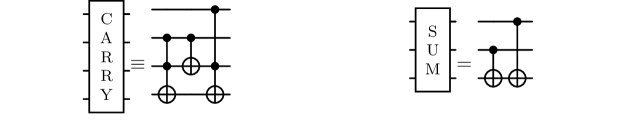
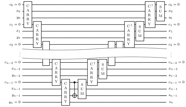
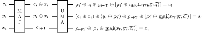
One of the first implementations of a quantum adder had been proposed by Vedral, Barenko and Ekert (VBE) in [VBE96]. Such a circuit is built out of the auxiliary unitary gates and (see figure 4) computing the carry and the sum on a single bit.
The VBE implementation is subsumed by the following proposition.
Proposition 2.2 (VBE plain adder [VBE96]).
There is a circuit implementing an -bit quantum addition as per definition 2.1 using ancilla qubits and gates.
Proof.
-
1.
The circuit is initiated in the state
where for any .
-
2.
The first part of the circuit consists of a chain of carry gates. The -th gate computes the carry through the recursive equation (5) storing its value in register . At last, it computes the most significant bit of the result , expressed by the carry , storing it in the qubit , added to take into account the possible overflow. More precisely, the state after the chain of the different CARRY gates is:
-
3.
The central computes the second most significant bit of the sum, namely
-
4.
The last part of the circuit consists of a chain of and gates. Inverses of the gate appear to restore every qubit of the temporary register to its initial state . In particular, only after .
∎
CDKPM implementation
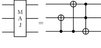
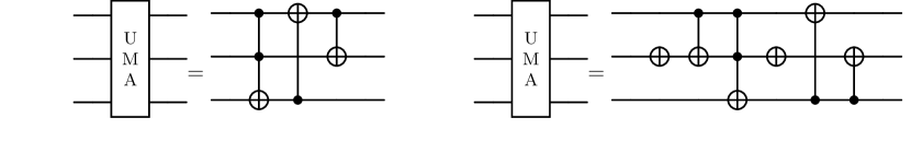
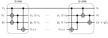
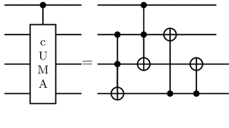
A subsequent advancement over the VBE implementation was proposed by Cuccaro, Draper, Kutin, and Petrie Moulton (CDKPM) in [Cuc+04]. Their strategy greatly improves the use of ancillary qubits, requiring only one ancilla in contrast to the linearly many qubits required by the VBE adder. Moreover, this circuit enjoys a smaller depth, uses fewer gates and requires less space. The CDKPM implementation is based on the two auxiliary gates (majority) and (unmajority and add). The gate is given in figure 6; it computes the majority function of three bits in place (See equation (5) in section 1.3), while the , given in figure 7 gate, restores the original values and writes the sum to the output as shown in figure 9.
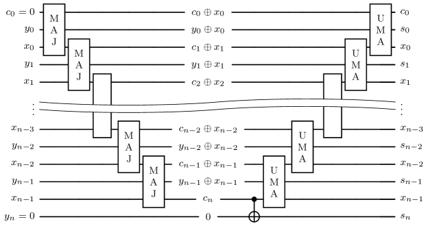
Proposition 2.3 (CDKPM plain adder [Cuc+04]).
There is a circuit implementing an -bit quantum addition as per definition 2.1 using ancilla qubit and gates.
Proof.
The sought circuit is given in figure 8. The first qubit is an ancilla prepared in the state , and the last qubit is the extra qubit meant to take into account the possible sum overflow. The circuit consists of a sequence of gates, a central copying the most significant carry in the register and a final sequence of gates. The combination of and gates is shown in figure 9. ∎
Gidney implementation
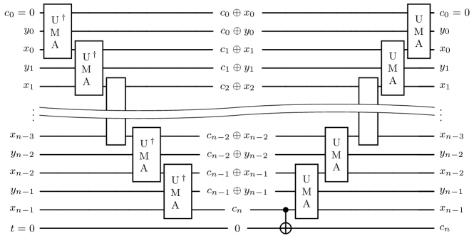
A variant of the CDKPM adder was proposed by Gidney [Gid18] (shown in figure 13). The implementation involves replacing gates in the blocks by a temporary logical- stored in an ancilla qubit. This increases the number of ancillas by : one for each of the blocks. In the blocks, the uncomputation of the gate is performed by a measurement and classically controlled - gate (using MBU). We show a block of Gidney’s original contruction below.

Proposition 2.4 (Gidney adder [Gid18]).
There is a circuit implementing an -bit quantum adder as per definition 2.1 using ancilla qubits and gates.
Proof.
An adder block in the temp logical- adder is constructed as shown in figure 12. The full circuit is shown in figure 13, it uses blocks, blocks, and additional s. We require less block with respect to the CDKPM implementation because the final block computes the most significant carry bit which also happens to the be most significant bit of the addition . We only use the two additional ’s for restoring the values of and computing the second most significant bit of the sum i.e. . ∎
Draper implementation
While the implementations described in the previous sections use essentially classical algorithms for addition and convert them to reversible quantum circuits, Draper [Dra00] came up with a quantum-specific way of addition using gates.
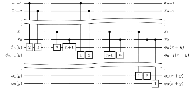
Proposition 2.5 (Draper’s plain adder [Dra00]).
Let be two bit strings stored in register and of size and respectively (the most significant bit of register is set to 0). Also, let . There is a circuit performing the operation
using zero ancilla qubits, and
Proof.
We denote as the -th qubit of . For , the following operations are performed in Draper’s circuit (see figure 14). Consider , the unitary acting on . The transformation on is as follows:
We see that the qubit of the target register , that is , now holds the qubit of the Fourier transformed sum i.e. . Hence, generalising the above result on the entire state of the target register, we conclude that the Draper adder performs the operation
The circuit on qubits has the same structure as a circuit, excluding a gate and all the gates. Therefore, the gate count of the circuit is:
∎
Remark 2.6.
Resource-wise, is bounded above by the cost of a gate.
In Draper’s original circuit, he considers the register to be prepared beforehand, and the final output to be in the state after the addition. However, to stay consistent with definition 2.1, we must take into account the cost of the to prepare , and the cost of the to return back to the computation basis at the end of the addition. Hence, we derive the following corollary.
Corollary 2.7 (Draper’s QFT-adder).
Let be two bit strings stored in register and of size and respectively (the most significant bit of register is set to 0). There is a circuit implementing a quantum adder as per definition 2.1 using ancilla qubits. The circuit gate cost is bounded above by the cost of circuits.
2.1 Controlled addition
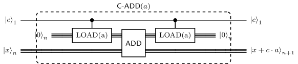
Definition 2.8 (Controlled addition).
We define a controlled quantum adder as any unitary gate implementing the strings addition controlled on a qubit according to the following circuit
![[Uncaptioned image]](/html/2407.20167/assets/x16.png) |
| Procedure | Tof Count | Ancillas | CNOT | Ref. |
| CDKPM | thm. 2.12 | |||
| Gidney | prop. 2.11 | |||
| Tof Count | Ancillas | Ref. | ||
| Draper | thm. 2.14 |
The theorem below gives a general recipe to perform a controlled addition given any adder.
Theorem 2.9 (Controlled adder - with extra ancillas and extra gate).
Proof.
We first initialize a circuit in the state
| Now, we use a sequence of gates to load a controlled version of the addend i.e. | ||||
| We can now perform the required addition using as our addend | ||||
| We finally unload using gates | ||||
∎
The loading of is performed in a register initially in the state. This can be executed with just a temporary logical-, and therefore can be uncomputed using measurements as in the case of the Gidney plain adder (proposition 2.4). This leads to the following corollary.
Corollary 2.10 (Controlled adder - extra ancillas and extra gates).
Although theorem 2.9 and corollary 2.10 can be used with any general adder, Gindey [Gid18] adapted his temporary logical- construction to give an adder that uses only an additional gates, and a single extra ancilla. We present his construction below.
Proposition 2.11 (Controlled adder - Gidney - with 1 extra ancilla [Gid18]).
There is a circuit implementing an -bit controlled quantum addition as per definition 2.8 using ancilla qubits and gates.
Proof.
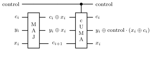
Figure 15 is taken from Gidney’s construction of a controlled adder building block. Here, we can isolate what happens in the case of a single pair, and show what is the resultant state. Apart from the gates of the blocks, we also require a gate per block to perform the controlled addition, leading to gates in total to execute a controlled adder in this case. ∎

We now show a version of the CDKPM adder that can perform controlled addition with a single ancilla qubit.
Theorem 2.12 (Controlled adder - CDKPM - with ancilla).
There is a circuit implementing an -bit controlled quantum addition as per definition 2.8 using ancilla qubit and gates.
Proof.
Controlled addition can be achieved by slightly modifying the CDKPM circuit (see figure 8) substituting the UMA gates with their controlled version given by figure 16.
Overall, the consecutive application of and gates acts as figure 17, thus determining the sought implementation of a controlled addition.
∎
While the Draper adder (as defined in corollary 2.7 employing three ’s) fits into the general framework of corollary 2.10, an alternate construction can be derived using only a single ancilla. The symmetries in the circuit can be exploited to avoid controls on every gate in the controlled Draper. Only the central gate would need to be controlled, while the the quantum Fourier transforms at the beginning and the end of the circuit remain uncontrolled.
Theorem 2.13 (Controlled adder - Draper).
Let be two bit strings, and be a control. Also, let be the Draper adder circuit described in corollary 2.7, performing the operation
We can perform a controlled Draper adder using a , a single controlled (performing ), and an
Proof.
Start with a quantum Fourier transform
| Then, one performs a | ||||
| followed by a gate to return the required state back to the computation basis | ||||
∎
Below, we show a way to execute the (as introduced in theorem 2.13) using a single ancilla and extra gates.
Theorem 2.14 (Controlled adder - Draper - with 1 ancilla).
Proof.
Following up from the above theorem 2.13, we find a construction for , requiring only a single ancilla. We first notice that all gates in commute. Therefore, the order in which they are performed is irrelevant. Secondly, the main difference between and is that any controlled rotation (for any ), now becomes a double controlled rotation gate:
We can decompose any gate it into a temporary logical-, a single controlled rotation, followed by an uncomputation of the logical-:
Using the above decomposition, we can convert every into a temporary logical- + (and finally an uncomputation of the temporary logical-).
We can now perform the required rotation gates that initially had as the control, by using as our control instead. Compared to , we require an extra for the temp logical-’s, gates and gates in expectation (cost of uncomputation of logical s) in total for . We only require a single ancilla as the ancilla is reset after every gate. The cost can be made cheaper by noticing that we can rearrange the order of the controlled rotation gates in and group all gates that have a common control . This construction requires only an additional gates (cost of logical s), gates and gates in expectation (cost of uncomputation of the logical s). ∎
2.2 Addition by a constant
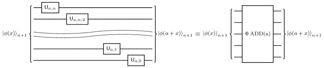
Definition 2.15 (Addition by a constant).
We define a quantum adder by a constant as any unitary gate implementing the strings addition by a classically known constant according to the following circuit
Such a gate can be obtained from any given quantum adder implementation in several ways. In this section, we present a way to perform addition by a constant using any circuit as per definition 2.1. We also dive into more specific implementations.
| Procedure | Tof Count | Ancillas | CNOT | Ref. |
| CDKPM | prop. 2.16 | |||
| Gidney | prop. 2.16 | |||
| Ancillas | Ref. | |||
| Draper | prop. 2.17 |
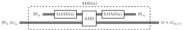
Proposition 2.16 (Adder by a constant [Cuc+04]).
Proof.
This circuit can be obtained first by performing the mapping
using NOT gates (one on each qubits such that ) and treating the first qubits input as an ancillary channel. Then, we use the adder circuit , to perform the required addition
Finally, we uncompute the ancilla register storing by applying the previous sequence of not gates again.
The corresponding circuit is depicted in figure 18, keeping implicit the ancillary qubits required by .
∎
While proposition 2.16 is applicable to any adder that can perform the mapping , in the case of Draper’s adder, there is a method to add constants without requiring ancillas. This method was used by Beauregard [Bea02].
Proposition 2.17 (Adder by a constant - Draper [Bea02]).
There is a circuit implementing an -bit addition by a constant as per definition 2.15 using ancillas.
Proof.
2.3 Controlled addition by a constant
Definition 2.18 (Controlled addition by a constant).
We define a controlled quantum adder as any unitary gate implementing the strings addition, by a classically known constant and controlled on a qubit , according to the following circuit
| Procedure | Tof Count | Ancillas | CNOT | Ref. |
| CDKPM | prop. 2.19 | |||
| Gidney | prop. 2.19 | |||
| Ancillas | Ref. | |||
| Draper | prop. 2.20 |
We now present a known construction that works with any adder to perform a controlled addition by a constant as per definition 2.18
Proposition 2.19 (Controlled adder by a constant [VBE96]).
Proof.
This circuit can be obtained first by performing the mapping
using CNOT gates. Then, we use the adder circuit, leaving the registers in the state
Finally, one has to uncompute the register storing , applying the previous sequence of CNOT gates again. The corresponding circuit is depicted in figure 20 keeping implied the ancillary qubits required by .
∎
Similarly to the previous section, one can adapt Draper’s implementation to suitably implement the gate of definition 2.18.
Proposition 2.20 (Controlled adder by a constant - Draper [Bea02]).
There is a circuit performing an -bit controlled addition by a constant as per definition 2.18 with zero ancilla qubits.
Proof.
We reuse the construction of proposition 2.17 and add controls to every rotation gate. The cost of this circuit depends on the binary representation of . We define as the gate performing the operation
∎
2.4 Subtraction
Definition 2.21 (Quantum subtraction).
We define a quantum subtractor as any unitary gate implementing the strings subtraction (see definition 1.5) according to the following circuit
![[Uncaptioned image]](/html/2407.20167/assets/x25.png) |
Due to the unitarity of the quantum adder gate and the uniqueness of the adjoint, it follows that implements a quantum subtractor. Alternatively, one can implement a quantum subtractor directly from the definition of bit-string subtractions.
Theorem 2.22.
The following two circuits implement a quantum subtractor.
| (8) |
| (9) |
Proof.
By definition, the gate flips all bits of a given register namely producing the state , i.e. the ’s complement of the string (see definition 1.3). Therefore, the circuit 8 implements bit string subtraction as given by definition 1.5. On the other hand, the second circuit in theorem 2.22 implements subtraction using the ’s complement of the second addend as given by proposition A.1 in the appendix. ∎
Interestingly, we recall that the gate performing addition by , i.e. the “increment by one” operator, enjoys a more specialized implementation [Gid15].
Remark 2.23 (Adjoint of Gidney Adder).
While a subtractor can be built using an adjoint of the adder, circuits involving a measurement (e.g. logical- adder) are generally not invertible. One way to invert the logical- adder is to swap the roles of the computation (logical-) and uncomputation (MBU uncomputation of logical-) of the logical-’s in the circuit.
2.5 Comparison
As expressed by proposition A.3 in appendix A, given a quantum subtractor, one can easily obtain a string comparator reading the sign (i.e. the most significant bit) of the difference.
Definition 2.24 (Quantum comparison).
We define a quantum comparator as any unitary gate implementing the strings comparison according to the following circuit
![[Uncaptioned image]](/html/2407.20167/assets/x28.png) |
where coincides with the most significant bit of , i.e. is when and otherwise.
| Procedure | Tof Count | Ancillas | CNOT | Ref. |
| CDKPM | prop. 2.27 | |||
| Gidney | prop. 2.28 | |||
| Ancillas | Ref. | |||
| Draper | prop. 2.26 |
Due to the close link between the string subtraction and the string comparison algorithm, it is possible to implement a quantum comparator by adapting the implementations of quantum adder proposed in the previous section.
Proposition 2.25 (Comparator - using an adder and a subtractor [VBE96]).
Let be a quantum circuit that performs an -bit quantum addition as per definition 2.1 using ancillas, and gates. Additionally, let be a quantum circuit that performs an -bit quantum subtraction as per definition 2.21 using ancillas, and gates. Then, there is a circuit implementing an -bit quantum comparator as per definition 2.24 using ancilla qubits and gates as well as an additional
Proof.
This circuit can be obtained first by performing the mapping
Here, the value most significant bit of i.e. gives us the required comparator output . Therefore, applying a on the target register with the most significant qubit of as the control, we get
We can now apply to return back to the required state
∎
The circuit described below is a component of the modular addition circuit described by Beauregard [Bea02], which is based on the Draper adder circuit (proposition 2.5).
Proposition 2.26 (Comparator - Draper/Beauregard [Bea02]).
Let be two bit strings stored in register and of size and respectively (the most significant bit of register is set to 0). There is a circuit performing a quantum comparison as per definition 2.24 using , , , and gates, and a single ancilla qubit.
Proof.
We can directly apply proposition 2.25 giving a comparator using an adder and a subtractor. Start preparing the register in the Fourier space.
| Then, perform a on the register (subtracting by ), as the significant bit of this subtraction is 1 only when . | ||||
| We now return back to the computational basis using a | ||||
| Controlling on and copying the most significant qubit of the difference i.e. , we compute the required comparison | ||||
| The final set of operations described below, now return the value to its original state | ||||
∎
Although the comparator described in proposition 2.25 works for any adder and subtractor, based on the type of adder used, there are more specific constructions requiring fewer gates.
Proposition 2.27 (Comparator - CDKPM - using half a subtractor [Cuc+04]).
There is a circuit implementing an -bit quantum comparator as per definition 2.24 using ancilla qubit and gates.
Proof.
The sought circuit is given by figure 21. Recall that the adjoint of a unitary quantum adder performs a subtraction. Notice that the first part of the circuit is one-half the adjoint of the CDKPM implementation of the adder. Comparing the definition of the UMA gate, see figure 7, with the definition of the borrowing , given by equation (6) of definition 1.5, one can see that the first sequence of accumulate in the register the value of the borrow, in particular . By construction, see also proposition A.5, computes the overflow of i.e. is whenever . The subsequent CNOT copies the latter value in the extra register , and the following sequence of UMA gate uncomputes the previous operation.
∎
The above comparator can also be executed using the temporary logical- gate of Gidney, which consumes more ancillas (to store the temporary logical and) in comparison to proposition 2.27
Proposition 2.28 (Comparator - Gidney - using half a subtractor).
There is a circuit implementing an -bit quantum comparator as per definition 2.24 using ancilla qubits and gates.
One can also easily realise a controlled implementation of the comparator employing the previous addition circuits.
Definition 2.29 (Controlled quantum comparison).
We define a controlled quantum comparator as any unitary gate implementing the bits strings comparison according to the following circuit
![[Uncaptioned image]](/html/2407.20167/assets/x30.png) |
Proposition 2.30 (Controlled comparator - CDKPM - using half a subtractor [Cuc+04]).
There is a circuit implementing an -bit controlled comparator as per definition 2.29 using ancilla qubits and gates.
Proof.
The comparator is controlled by a qubit . From proposition 2.27, we see that the output of the comparator is computed as the most significant bit of the subtraction of and . The that copies the comparator value after the chain of ’s needs to now be controlled, thus leading to an extra gate. ∎
The previous quantum controlled comparator can also be executed using the temporary logical- gate of Gidney, which consumes more ancillas (to store the temporary logical AND) in comparison to proposition 2.30 but requires fewer gates.
Proposition 2.31 (Controlled comparator - Gidney - using half a subtractor).
There is a circuit implementing an -bit controlled quantum comparator as per definition 2.29 using ancilla qubits and .
When comparing registers, we note that they may not always be of equal size . When registers and with , one can circumvent this problem by padding the register with an extra qubits and perform the comparison on two qubit registers. However, there is a slightly more efficient solution available for the CDKPM and Gidney adders.
Remark 2.32.
Assume that without loss of generality. Let represent the first bits of , notice that . Therefore, the computing the required comparison now becomes a gate, with controls and . Thus using a single extra gate with no extra ancillas.
We now explore constructions for comparing a quantum register with a classical value.
Definition 2.33 (Quantum comparison with a classical constant).
We define a quantum comparator with a classical constant as any unitary gate implementing the strings comparison with according to the following circuit
![[Uncaptioned image]](/html/2407.20167/assets/x31.png) |
where coincides with the most significant bit of i.e is when and otherwise.
Proposition 2.34 (Comparator by a classical constant).
Proof.
Similar to the idea in proposition 2.16, we first use an qubit register to load our constant into memory by applying NOT gates (one for each bit ), giving the state
Now, we apply the comparator circuit with inputs on target
The ancilla is then uncomputed by applying the previous sequence of NOT gates a second time
∎
Similar to the construction in proposition 2.25, a comparator by a classical constant can be constructed by using an adder and a subtractor, as shown below.
Theorem 2.35 (Comparator with a classical constant - using an adder by a constant and a subtractor by a constant).
Let be a circuit performing an -bit addition by a constant as per definition 2.15, using gates and ancillas. Also, let be a circuit performing an -bit subtraction by a constant as per definitions 2.15 and 2.21, using gates and ancillas. Then, there is a circuit implementing an -bit comparator by a classical constant as per definition 2.33 using gates, an additional gate and ancilla qubits
Proof.
The idea is similar to proposition 2.25 giving a comparator using an adder and a subtractor. ∎
Now, theorem 2.35 can be applied specifically to the case of the Draper adder to give the theorem below.
Proposition 2.36 (Comparator by a classical constant - Draper/Beauregard [Bea02]).
Let be two bit strings. There is a circuit implementing a comparator by a classical constant:
using a circuit with , , , and gates, and a single ancilla qubit.
Proof.
Using and in theorem 2.35, we require only a single ancilla. ∎
Definition 2.37 (Controlled comparison by a classical constant).
We define a controlled quantum comparator with a classical constant as any unitary gate implementing the strings comparison with according to the following circuit
![[Uncaptioned image]](/html/2407.20167/assets/x32.png) |
Theorem 2.38 (Controlled comparator by a classical constant - CDKPM - using half a subtractor).
There is a circuit implementing an -bit controlled comparator by a classical constant as per definition 2.37 using ancilla qubits and gates
Proof.
The previous statement follows by using a comparator with classical constant (proposition 2.34) and using an ancilla register for writing (controlled on the register ) the value of using CNOTs, which gets uncomputed after using the comparator. ∎
Remark 2.39.
Given any circuit implementing the comparison as defined in definition 2.24 one can get the opposite comparison by simply postcomposing the first circuit with an gate acting on register .
3 Quantum modular addition
In this section, we detail and build on the methods of Vedral et. al [VBE96] for constructing modular adders as a suitable combination of the circuits for addition, subtraction and comparison introduced in section 2.
Definition 3.1 (Modular addition).
Let be two bit strings, and classically known with . We define a quantum modular adder as any unitary gate implementing the strings addition modulo according to the following circuit
![[Uncaptioned image]](/html/2407.20167/assets/x33.png) |
Proposition 3.2 (Modular adder - Vedral’s architecture [VBE96]).
Let
-
•
be a quantum circuit that performs a quantum addition using ancillas, and gates,
-
•
be a quantum comparator with a classical constant using ancillas, gates,
-
•
be a quantum circuit that performs a (controlled) subtraction by a constant using ancillas, and gates,
-
•
: be a quantum comparator using ( ancillas, gates).
There is a circuit, , performing the -bit modular addition operation as per definition 3.1 using gates and ancillas.
Proof.
We start with a plain addition into our target
Using our comparator , we can perform a comparison of the previous sum with the given modulus
When the comparator’s output is , i.e. when , we need to subtract the modulus to compute the correct sum . Therefore, we perform a controlled subtraction of in the register currently storing (Note: We need to flip, using an gate, the value of the comparison qubit before performing our controlled subtraction as pointed out in remark 2.39)
Finally, we need to uncompute our previously computed output of the comparator. We notice that whenever strictly. Namely, call then hence
Therefore, we can use on inputs and to perform the final step
∎
Remark 3.3.
In principle, one can implement a subroutine computing for any given number as follows
![[Uncaptioned image]](/html/2407.20167/assets/x35.png) |
Therefore, a circuit computing can be alternatively given by
![[Uncaptioned image]](/html/2407.20167/assets/x36.png) |
Proposition 3.2 gives an overview for constructing modular adders using any available combination of adders, (controlled) subtractor (by a constant), and comparators (by a constant). In the theorems below, we delve into specific adder circuits used for modular addition and calculate concrete costs more thoroughly.
Proposition 3.4 (Modular adder - CDKPM [Cuc+04]).
There is a circuit, , performing the -bit modular addition operation as per definition 3.1 using ancillas and gates.
Proof.
We employ proposition 3.2 with the following subroutines:
-
•
: CDKPM plain adder (proposition 2.3);
-
•
: CDKPM half subtractor based constant comparator proposition 2.27;
- •
-
•
: CDKPM half subtractor based comparator proposition 2.27.
From proposition 3.2, we know that the total cost of performing modular addition using the above selection of subroutines is gates. Similarly, the number of ancillas required is .
∎
The version presented above has essentially the same structure of [VBE96] but enjoys some improvements. Namely, we use CDKPM’s adder (in proposition 2.3 instead of proposition 2.2), and we substitute the use of two adder circuits for the comparator (proposition 2.25) with a single comparator circuit. These changes are already known in the literature (e.g. [Lit23]), but it is not often mentioned the use of ancilla qubits for internal operations. If one has access to ancillas, one can use Gidney’s adder (proposition 2.4 instead of the CDKPM adder (i.e. proposition 2.3). This allows for a decrease in the number of gates and also the depth.
Proposition 3.5 (Modular adder - Gidney [Gid18]).
There is a circuit, , performing the -bit modular addition operation as per definition 3.1 using ancillas and gates.
Proof.
The proof follows the same steps as proposition 3.4. We leverage proposition 3.2, with the following subroutines:
-
•
: Gidney plain adder (proposition 2.4);
-
•
: Gidney half subtractor based constant comparator proposition 2.28;
- •
-
•
: Gidney half subtractor based comparator proposition 2.28.
From proposition 3.2, we know that the total cost of performing modular addition using the above selection of subroutines is gates. Similarly, the number of ancillas required is . ∎
The above modular adder can be further modified to reduce the number of ancillas. We propose to use the Gidney adder only for the first addition and final comparison, and use the CDKPM adder for the constant subtraction and constant comparison, thus giving us the following result.
Theorem 3.6 (Modular adder - Gidney + CDKPM).
There is a circuit, , performing the -bit modular addition operation as per definition 3.1 using ancillas and gates.
Proof.
The proof follows the same steps as the proof of proposition 3.4. In particular:
-
•
: Gidney plain adder (proposition 2.4);
-
•
: CDKPM half subtractor based constant comparator proposition 2.27;
- •
-
•
: Gidney half subtractor based comparator (proposition 2.28).
From proposition 3.2, we know that the total cost of performing modular addition using the above selection of subroutines is gates. Similarly, the number of ancillas required is ancillas. ∎
Proposition 3.7 (Modular adder - Draper/Beauregard [Bea02]).
There is a circuit, , performing the -bit modular addition operation as per definition 3.1 with a gate count of ’s, ’s, ’s, ’s, , , , and ancillas.
Proof.
We leverage proposition 3.2, with the following subroutines:
-
•
: Draper plain adder corollary 2.7;
-
•
: Draper’s comparator by a classical constant proposition 2.36;
- •
-
•
: Draper/Beauregard comparator proposition 2.26.
The of cancels with the of . We also find similar reductions for pairs the ’s/’s of and . The total gate count is therefore, ’s, ’s, ’s, ’s, , , and . The number of ancillas required is ∎
3.1 Controlled modular addition
Definition 3.8 (Controlled modular addition).
We will denote controlled modular addition (with modulus ) as the following circuit
![[Uncaptioned image]](/html/2407.20167/assets/x37.png) |
A naive approach to creating a controlled modular adder is to add an extra control to each gate of the four subroutines composing the modular adder described in proposition 3.2. However, there is a more efficient approach where only the first adder and final comparator need to be controlled. Such a trick has been mentioned in [Lit23] without providing a proof.
Proposition 3.9 (Controlled modular adder).
Let
-
•
be a quantum circuit that performs a quantum (controlled) addition using ancillas, and gates;
-
•
be a quantum comparator by a constant , using ancillas, gates;
-
•
be a quantum circuit that performs a quantum subtraction by a constant , using ancillas, and gates;
-
•
: be a controlled quantum comparator using ( ancillas, gates).
There is a circuit , performing the -bit controlled modular addition operation as per definition 3.8, using gates and ancillas.
Proof.
In order to perform a controlled modular adder, start by first performing out controlled addition of the addend into the target register
| We can now follow the step similar to the modular addition protocol, where we perform a constant comparison | ||||
| Once again, similar to the modular addition protocol, we perform a controlled subtraction of the modulus , controlled on our comparator’s output because if , then the modulus needs to be subtract to reduce the sum . Note: We need to first flip the comparison qubit, and then perform the controlled subtraction (see remark 2.39) | ||||
| We need to now uncompute the value initally computed by . As in the modular addition case, we need to find a comparison operation that is equivalent to (the qubit we wish to uncompute/reset). Since , one finds out that and in particular since is false whenever from the condition . The only difference here compared to proposition 3.2 is that the comparator bit is only set for states with , with the control bit set. The required operation is nothing but a controlled comparison, with control , inputs and | ||||
∎
We will now explore some costs of controlled modular adders for a few specific combinations of subroutines.
Proposition 3.10 (Controlled modular adder - CDKPM).
There is a circuit , performing the -bit controlled modular addition operation as per definition 3.8, using ancillas and gates.
Proof.
We implement a controlled modular adder by using proposition 3.9 in conjunction with the following subroutines:
-
•
be a quantum circuit that performs a quantum (controlled) using a CDKPM adder with a single extra ancilla (theorem 2.12) requiring ancillas, and gates;
-
•
be a quantum comparator by a constant using Controlled comparator - using half a CDKPM subtractor (theorem 2.38), requiring ancillas, gates;
-
•
be a quantum circuit that performs a quantum subtraction by a constant using the CDKPM adder in proposition 2.16, requiring ancillas, and gates;
-
•
be the quantum comparator described in proposition 2.30: Controlled comparator - using half a CDKPM subtractor. This subroutine requires ancilla, gates.
There is a circuit , performing the controlled modular addition operation as per definition 3.8, using gates and ancillas. ∎
Proposition 3.11 (Controlled modular adder - Gidney).
There is a circuit , performing the -bit controlled modular addition operation as per definition 3.8, using ancillas and gates.
Proof.
We implement a controlled modular adder by using proposition 3.9 in conjunction with the following subroutines:
-
•
be a quantum circuit that performs a quantum (controlled) using a Gidney adder with a single extra ancilla (proposition 2.11) requiring ancillas, and gates;
-
•
be a quantum comparator by a constant using Controlled comparator - using half a Gidney subtractor (proposition 2.31), requiring ancillas, gates;
-
•
be a quantum circuit that performs a controlled quantum subtraction by a constant using the Gidney adder in proposition 2.16, requiring ancillas, and gates;
-
•
be the controlled quantum comparator described in proposition 2.31: controlled comparator - using half a Gidney subtractor. This subroutine requires ancillas, gates.
According to proposition 3.9, there is a circuit performing the operation
using gates and ancillas. ∎
3.2 Modular addition by a constant
Definition 3.12 (Modular addition by a constant).
Let . Assume to know classically with . We will denote modular addition by a constant (with modulus ) with the following circuit
A simple way to perform a modular addition by a constant is by using a quantum modular adder as given by definition 3.1.
Proposition 3.13 (Modular adder by a constant).
Proof.
Similar to the proposition 2.16, We first take an unused qubit register, and load the value using gates
| We now perform the required modular addition | ||||
| Finally, we unload the constant | ||||
∎
The above construction works for any modular adder construction that performs the operation . However, when examining the VBE architecture, we can modify certain subroutines to enable a different approach to performing constant modular addition.
Theorem 3.14 (Modular adder by a constant - in VBE architecture).
Let
-
•
be a quantum circuit that performs a constant quantum addition using ancillas, and gates;
-
•
be a quantum comparator using ancillas, gates;
-
•
be a quantum circuit that performs a (controlled) subtraction by a constant using ancillas, and gates;
-
•
: be a constant quantum comparator using ( ancillas, gates).
there is a circuit implementing an -bit quantum modular addition by a constant as per definition 3.12 using gates and ancillas.
Proof.
The proof is very similar to the proof of the VBE modular adder architecture (proposition 3.2). We start with an addition by a constant into our target
Using our comparator , we can perform a comparison of the previous sum with our modulus
When the comparator’s output is , i.e. when , we need to subtract the modulus to compute the correct sum . Therefore, we perform a controlled subtraction of in the register currently storing (note: we need to flip, using an gate, the value of the comparison qubit before performing our controlled subtraction):
We finally need to uncompute the comparator qubit. We notice that , therefore, we can use on inputs and to perform the final step
∎
Given that we are adding by a constant, various ways exist to create more cost-effective modular addition circuits by modifying the plain addition implemented in the modular adder. Takahashi [Tak09] in 2009 was the first to observe that the initial two operations in the VBE modular architecture could be merged into a single operation when performing a constant modular addition.
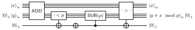
Proposition 3.15 (Modular adder by a constant - in Takahashi architecture [TTK09]).
Let
-
•
be a quantum circuit that performs a constant quantum subtraction using ancillas, and gates;
-
•
be a quantum circuit that performs a (controlled) addition by a constant using ancillas, and gates;
-
•
be a classical comparator using ancillas, gates.
there is a circuit implementing an -bit quantum modular addition by a constant as per definition 3.12 using gates and ancillas.
Proof.
To perform the unitary operation , we start subtracting (which is different from the first step of proposition 3.2, where we add )
| Now, we need to add back to those states whenever . Notice that , i.e. the most significant bit of is only when . Controlled on , we add back | ||||
| Now, as we have seen many times before, we have to find an operation that uncomputes . We notice that since . Therefore, we can use a constant comparator followed by a NOT to perform the required reset/uncomputation | ||||
∎
3.3 Controlled modular addition by a constant
Definition 3.16 (Controlled modular addition by a constant).
Given (with classically known), and a control with . We will denote controlled modular addition by a constant (with modulus ) with the following circuit
A simple way to perform a controlled modular addition by a constant is by using a quantum modular adder as per definition 3.1.
Theorem 3.17 (Controlled modular adder by a constant).
Proof.
The technique is similar to what we have used in many previous cases when an operation by a constant is involved. We first take an unused qubit register, and load the value (controlled on ) using gates
| We now perform the required modular addition | ||||
| We have to finally unload the constant | ||||
∎
The above construction works for any modular adder construction that performs the operation . However, if we look at the VBE architecture specifically, we can modify some of the subroutines to provide a different method for performing a controlled constant modular addition.
Proposition 3.18 (Controlled modular adder by a constant - in VBE architecture [VBE96]).
Let
-
•
be a quantum circuit that performs a controlled constant addition using ancillas, and gates;
-
•
be a quantum comparator using ancillas, gates;
-
•
be a quantum circuit that performs a (controlled) subtraction by a constant using ancillas, and gates;
-
•
: be a controlled constant quantum comparator using ( ancillas, gates).
There is a circuit implementing an -bit controlled quantum modular addition by a constant as per definition 3.16 using gates and ancillas.
Proof.
The proof is very similar to the proof of the VBE modular adder architecture (proposition 3.2). We start with a controlled addition by a constant into our target
Using our comparator , we can perform a comparison of the previous sum with our modulus
When the comparator’s output is 0, i.e. when , we need to subtract the modulus to compute the correct sum . Therefore, we perform a controlled subtraction of in the register currently storing (Note: We need to flip, using an gate, the value of the comparison qubit before performing our controlled subtraction )
We finally need to uncompute our previously computed output of the comparator. We notice that (similar to the proof of proposition 3.9), therefore, we can use on inputs and to perform the final step
∎
A -based controlled constant modular adder was proposed by Beauregard [Bea02], and works by combining the VBE architecture with Draper’s adder [Dra00] (proposition 2.5). We propose a slightly modified proof below.
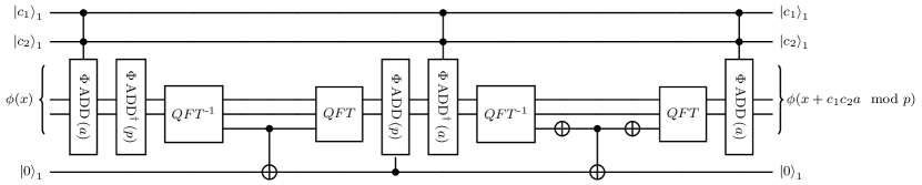
Proposition 3.19 (Controlled modular adder by a constant - Beauregard [Bea02]).
There is a circuit implementing an -bit controlled quantum modular addition by a constant as per definition 3.16 with a gate count of ’s, ’s, ’s, , , , , , and ancillas.
Proof.
We use the following subroutines. Let
-
•
be Draper’s controlled adder by a constant (proposition 2.20), using ancillas;
-
•
be a quantum comparator based on proposition 2.36, using ancilla;
-
•
be a quantum circuit that performs a controlled subtraction by a constant based on proposition 2.20 using ancillas;
-
•
: be a controlled quantum comparator by a constant as derived in theorem 2.38 using ancilla.
Note that adjacent s and s can cancel out. The total gate count is therefore, ’s, ’s, ’s, , , , , and . The number of ancillas required is ∎
In proposition 3.19, the modular addition circuit is based on a single controlled adder. For completeness, we also share Beauregard’s [Bea02] original circuit in figure 23 which uses two controls, and also uses a slightly different set of gates..
4 Measurement-based uncomputation speed-ups
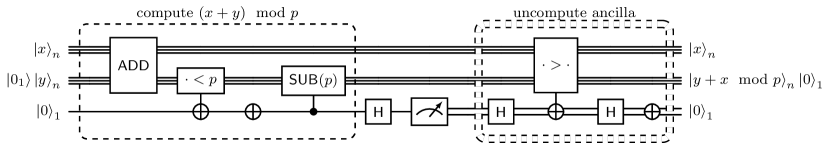
We are now prepared to present the proof of the MBU lemma and its applications to modular arithmetic. The MBU algorithm for uncomputing a single qubit is the circuit that can be found in figure 24. Recall that MBU has already been introduced in [Gid18] (for the special case of gates) but here we formalize this method for the single-qubit uncomputation of any unitary. Attempts at generalization of MBU to perform multi-qubit computation has been already treated in the literature, see e.g. [Gid19b].

Lemma 4.1 (Measurement-based uncomputation lemma).
Let be a function, and let be a self-adjoint -qubit unitary that implements as follows:
There is an algorithm performing the mapping
using with probability , gates, and gate. It also involves one single-qubit computational basis measurement and a single gate.
Proof.
The algorithm is described in figure 24. We first apply the Hadamard gate on the register and measure it in the computational basis. Since , the resulting outcomes is or with equal probabilities. If we obtain , we successfully uncomputed the register, leaving the registers in the state . On the other hand, if we get the outcome , the state at this point is We then apply another Hadamard to , followed by . This performs a phase kickback, leaving the quantum computer in the state
Applying on another Hadamard and a NOT gate results in the final state . ∎
4.1 Modular addition
Theorem 4.2 (MBU modular adder - VBE architecture).
Let
-
•
be a quantum circuit that performs a quantum addition using ancillas, and gates;
-
•
be a quantum comparator using ancillas, gates;
-
•
be a quantum circuit that performs a (controlled) subtraction by a constant using ancillas, and gates;
-
•
: be a quantum comparator using ( ancillas, gates).
There is a circuit, , performing the -bit modular addition operation as per definition 3.1 using gates in expectation and
ancillas.
Proof.
As seen in the modular adder - VBE architecture (proposition 3.2), the first three subroutines perform the following mapping
The comparator qubit storing is finally supposed to be uncomputed using . We can apply the MBU lemma on the comparator qubit and the uncomputation subroutine , thus halving the cost of in expectation. Therefore, we finally get a cost of gates in expectation, and the same ancilla count at proposition 3.2. ∎
Theorem 4.3 (MBU modular adder - CDKPM).
There is a circuit, , performing the -bit modular addition operation as per definition 3.1 using ancillas and gates in expectation.
Proof.
For the CDKPM modular adder described in proposition 3.4, the following subroutines are used:
-
•
: CDKPM plain adder proposition 2.3;
-
•
: CDKPM half subtractor based constant comparator proposition 2.27;
-
•
: CDKPM plain adder, more concretely, we use in proposition 2.19.
-
•
: CDKPM half subtractor based comparator proposition 2.27.
Now, applying theorem 4.2, we find that our expected gate cost is
and the ancilla count is .
∎
Theorem 4.4 (MBU modular adder - Gidney).
There is a circuit, , performing the -bit modular addition operation as per definition 3.1 using ancillas, gates in expectation.
Proof.
Assume to access the following subroutines are used:
-
•
: Gidney plain adder proposition 2.4;
-
•
: Gidney half subtractor based constant comparator proposition 2.28;
-
•
: Gidney plain adder, more concretely, we use in proposition 2.19.
-
•
: Gidney half subtractor based comparator proposition 2.28.
Now, applying theorem 4.2, we find that our expected gate cost is
and the ancilla count is .
∎
Theorem 4.5 (MBU modular adder - Gidney + CDKPM).
There is a circuit, , performing the -bit modular addition operation as per definition 3.1 using ancillas, gates in expectation.
Proof.
For the Gidney+CDKPM modular adder described in theorem 4.5, the following subroutines are used:
-
•
: Gidney plain adder proposition 2.4;
-
•
: CDKPM half subtractor based constant comparator proposition 2.27;
-
•
: CDKPM plain adder, more concretely, we use in proposition 2.19.
-
•
: Gidney half subtractor based comparator proposition 2.28.
Now, applying theorem 4.2, we find that our expected gate cost is
and the ancilla count is . ∎
Theorem 4.6 (MBU modular adder - Draper/Beauregard).
Let be two bit strings, and classically known with . There is a circuit, , performing the modular addition operation as per definition 3.1 with an expected gate count of ’s, ’s, ’s, ’s, ’s, , , and ancillas.
Proof.
We leverage proposition 3.2, with the following subroutines:
-
•
: Draper plain adder corollary 2.7;
-
•
: Draper’s comparator by a classical constant proposition 2.36;
- •
-
•
: Draper/Beauregard comparator proposition 2.26.
The of cancels with the of . We also find similar reductions for pairs the ’s/’s of and . The expected gate count is therefore, ’s, ’s, ’s, ’s, ’s, , and . The number of ancillas required is . ∎
4.2 Controlled modular addition
Theorem 4.7 (MBU controlled modular adder - VBE architecture).
Let
-
•
be a quantum circuit that performs a quantum (controlled) addition using ancillas, and gates;
-
•
be a quantum comparator by a constant , using ancillas, gates;
-
•
be a quantum circuit that performs a quantum subtraction by a constant , using ancillas, and gates;
-
•
: be a controlled quantum comparator using ( ancillas and gates).
There is a circuit implementing an -bit controlled quantum modular addition as per definition 3.8 using gates in expectation and ancillas.
Proof.
As seen in the controlled modular adder - VBE architecture (proposition 3.9), the first three subroutines perform the following mapping
The comparator qubit storing is finally supposed to be uncomputed using . We can apply the MBU lemma here on the comparator qubit and the uncomputation subroutine , thus halving the cost of in expectation. Therefore, we finally get a cost of gates in expectation, and the same ancilla count as proposition 3.9. ∎
Theorem 4.8 (MBU controlled modular adder - CDKPM).
There is a circuit implementing an -bit controlled quantum modular addition as per definition 3.8 using ancillas and gates in expectation.
Proof.
For the controlled CDKPM modular adder described in proposition 3.10, the following subroutines are used:
-
•
be a quantum circuit that performs a quantum (controlled) using a CDKPM adder with a single extra ancilla (theorem 2.12) requiring ancillas, and gates;
-
•
be a quantum comparator by a constant using Controlled comparator - using half a CDKPM subtractor (theorem 2.38), requiring ancillas, gates;
-
•
be a quantum circuit that performs a quantum subtraction by a constant using the CDKPM adder in proposition 2.16, requiring ancillas, and gates;
-
•
be the controlled quantum comparator described in proposition 2.30: Controlled comparator - using half a CDKPM subtractor. This subroutine requires ancilla, gates.
Theorem 4.9 (MBU controlled modular adder - Gidney).
There is a circuit implementing an -bit controlled quantum modular addition as per definition 3.8 using ancillas, gates in expectation.
Proof.
For the Gidney controlled modular adder described in proposition 3.11, the following subroutines are used:
-
•
be a quantum circuit that performs a quantum (controlled) using a Gidney adder with a single extra ancilla (proposition 2.11) requiring ancillas, and gates;
-
•
be a quantum comparator by a constant using Controlled comparator - using half a Gidney subtractor (proposition 2.31), requiring ancillas, gates;
-
•
be a quantum circuit that performs a controlled quantum subtraction by a constant using the Gidney adder in proposition 2.16, requiring ancillas, and gates;
-
•
be the controlled quantum comparator described in proposition 2.31: controlled comparator - using half a Gidney subtractor. This subroutine requires ancillas, gates.
Now, applying theorem 4.2, we find that our expected gate cost is
and the ancilla count is . ∎
4.3 Modular addition by a constant
Theorem 4.10 (MBU modular addition by a constant - VBE architecture).
Let
-
•
be a quantum circuit that performs a constant quantum addition using ancillas, and gates;
-
•
be a quantum comparator using ancillas, gates;
-
•
be a quantum circuit that performs a (controlled) subtraction by a constant using ancillas, and gates;
-
•
: be a constant quantum comparator using ( ancillas, gates).
there is a circuit implementing an -bit quantum modular addition by a constant as per definition 3.12 using gates and ancillas.
Proof.
As seen in the constant modular adder in VBE architecture (theorem 3.14), the first three subroutines perform the following mapping
The comparator qubit storing is finally supposed to be uncomputed using . We can apply the MBU lemma here on the comparator qubit and the uncomputation subroutine , thus halving the cost of in expectation. Therefore, we finally get a cost of gates in expectation, and the same ancilla count at theorem 3.14. ∎
Theorem 4.11 (MBU modular adder by a constant - in Takahashi Architecture).
Let . Assume to know classically with . Also, assume we have access to the following subroutines:
-
•
be a quantum circuit that performs a constant quantum subtraction using ancillas, and gates;
-
•
be a quantum circuit that performs a (controlled) addition by a constant using ancillas, and gates;
-
•
be a classical comparator using ancillas, gates.
Then, there is a circuit implementing quantum modular addition by a constant as per definition 3.12 using gates in expectation and ancillas.
Proof.
As seen in the Takashi constant modular adder (proposition 3.15), the first two subroutines perform the following mapping
The comparator qubit storing is finally supposed to be uncomputed using and a NOT gate. We can apply the MBU lemma here on the comparator qubit and the uncomputation subroutine , thus halving the cost of in expectation. Therefore, we finally get a cost of gates in expectation, and the same ancilla count at proposition 3.15. ∎
4.4 Controlled modular addition by a constant
Theorem 4.12 (MBU controlled modular adder by a constant - VBE architecture).
Let
-
•
be a quantum circuit that performs a controlled addition by a constant using ancillas, and gates;
-
•
be a quantum comparator using ancillas, gates;
-
•
be a quantum circuit that performs a (controlled) subtraction by a constant using ancillas, and gates;
-
•
: be a controlled constant quantum comparator using ( ancillas, gates).
There is a circuit implementing an -bit controlled quantum modular addition by a constant as per definition 3.16 using gates and ancillas.
Proof.
As seen in the controlled modular adder by a constant in VBE architecture (proposition 3.18), the first three subroutines perform the following mapping
The comparator qubit storing is finally supposed to be uncomputed using . We can apply the MBU lemma here on the comparator qubit and the uncomputation subroutine , thus halving the cost of in expectation. Therefore, we finally get a cost of gates in expectation, and the same ancilla count at proposition 3.18. ∎
4.5 Two-sided comparison
The following result (stating directly the complexity with and without using MBU) checks if a register has a value in the range specified by two other quantum registers and . Compared to a non-MBU implementation, we save for the gate cost.
Theorem 4.13 (Two-sided comparator).
Let , and Let us assume we have access to , with
using ancillas and gates. Let us assume we also have access to , with
using ancillas and gates. Then, there is a circuit that performs the operation
using ancillas and gates.
Proof.
We begin by first checking if
| Next we compute whether controlled on , and store the output in our target. We know that , and since we have both the comparator values stored in memory | ||||
| We finally uncompute the intermediate value using | ||||
Therefore, we get a cost of . This cost can be decreased by applying the MBU lemma on the uncomputing , thus leading to a cost of . ∎
Acknowledgement
This work started when AS was working at Inveriant Pte. Ltd. AS is supported by Innovate UK under grant 10004359. AMM has received funding from the European Union’s Horizon 2020 research and innovation programme under the grant agreement N°101034324 and has been partially supported by the Italian Group for Algebraic and Geometric Structures and their Application (GNSAGA–INdAM). This work is supported by the National Research Foundation, Singapore, and A*STAR under its CQT Bridging Grant. We also acknowledge funding from the Quantum Engineering Programme (QEP 2.0) under grants NRF2021-QEP2-02-P05 and NRF2021-QEP2-02-P01. We thank Anupam Chattopadhyay and Zeyu Fan for useful discussions. AMM and AL thank Niels Benedikter for the hospitality at Università degli Studi di Milano.
References
- [Agg+17] Divesh Aggarwal, Gavin K Brennen, Troy Lee, Miklos Santha and Marco Tomamichel “Quantum attacks on Bitcoin, and how to protect against them” In arXiv preprint arXiv:1710.10377, 2017
- [Bab+18] Ryan Babbush, Craig Gidney, Dominic W Berry, Nathan Wiebe, Jarrod McClean, Alexandru Paler, Austin Fowler and Hartmut Neven “Encoding electronic spectra in quantum circuits with linear T complexity” In Physical Review X 8.4 APS, 2018, pp. 041015
- [Bea02] Stephane Beauregard “Circuit for Shor’s algorithm using 2n+ 3 qubits” In arXiv preprint quant-ph/0205095, 2002
- [Ben73] C.. Bennett “Logical Reversibility of Computation” In IBM Journal of Research and Development 17.6, 1973, pp. 525–532 DOI: 10.1147/rd.176.0525
- [Ben89] Charles H. Bennett “Time/Space Trade-offs for Reversible Computation” In SIAM Journal on Computing 18.4 SIAM, 1989, pp. 766–776 DOI: 10.1137/0218053
- [Ber+19] Dominic W Berry, Craig Gidney, Mario Motta, Jarrod R McClean and Ryan Babbush “Qubitization of arbitrary basis quantum chemistry leveraging sparsity and low rank factorization” In Quantum 3 Verein zur Förderung des Open Access Publizierens in den Quantenwissenschaften, 2019, pp. 208
- [Chi02] Andrew M. Childs “Quantum Information Processing in Continuous Time” In Quantum Information Processing 1 Springer, 2002, pp. 35–43 DOI: 10.1023/A:1019636608477
- [Cuc+04] Steven A Cuccaro, Thomas G Draper, Samuel A Kutin and David Petrie Moulton “A new quantum ripple-carry addition circuit” In arXiv preprint quant-ph/0410184, 2004
- [Dor+22] João F Doriguello, Alessandro Luongo, Jinge Bao, Patrick Rebentrost and Miklos Santha “Quantum Algorithm for Stochastic Optimal Stopping Problems with Applications in Finance” In 17th Conference on the Theory of Quantum Computation, Communication and Cryptography, 2022
- [Dra+04] Thomas G. Draper, Samuel A. Kutin, Eric M. Rains and Krysta M. Svore “A logarithmic-depth quantum carry-lookahead adder” arXiv, 2004 DOI: 10.48550/ARXIV.QUANT-PH/0406142
- [Dra00] Thomas G Draper “Addition on a quantum computer” In arXiv preprint quant-ph/0008033, 2000
- [Eke18] Martin Ekerå “Quantum algorithms for computing general discrete logarithms and orders with tradeoffs” In IACR Cryptol. ePrint Arch., 2018, pp. 797 URL: https://eprint.iacr.org/2018/797
- [GE21] Craig Gidney and Martin Ekerå “How to factor 2048 bit RSA integers in 8 hours using 20 million noisy qubits” In Quantum 5 Verein zur Förderung des Open Access Publizierens in den Quantenwissenschaften, 2021, pp. 433
- [Gid15] Craig Gidney “Constructing Large Increment Gates” Blog: Algorithmic Assertions, 2015 URL: https://algassert.com/circuits/2015/06/12/Constructing-Large-Increment-Gates.html
- [Gid18] Craig Gidney “Halving the cost of quantum addition” In Quantum 2 Verein zur Förderung des Open Access Publizierens in den Quantenwissenschaften, 2018, pp. 74
- [Gid19] Craig Gidney “Approximate encoded permutations and piecewise quantum adders” In arXiv preprint arXiv:1905.08488, 2019
- [Gid19a] Craig Gidney “Spooky Pebble Games and Irreversible Uncomputation” Blog: Algorithmic Assertions, 2019 URL: https://algassert.com/post/1905
- [Gid19b] Craig Gidney “Windowed quantum arithmetic” In arXiv preprint arXiv:1905.07682, 2019
- [Gou+23] Élie Gouzien, Diego Ruiz, Francois-Marie Le Régent, Jérémie Guillaud and Nicolas Sangouard “Performance Analysis of a Repetition Cat Code Architecture: Computing 256-bit Elliptic Curve Logarithm in 9 Hours with 126133 Cat Qubits” In Physical Review Letters 131.4 American Physical Society (APS), 2023 DOI: 10.1103/physrevlett.131.040602
- [HH10] David Harris and Sarah Harris “Digital design and computer architecture” Morgan Kaufmann, 2010
- [KSS21] Niels Kornerup, Jonathan Sadun and David Soloveichik “Tight Bounds on the Spooky Pebble Game: Recycling Qubits with Measurements” In arXiv preprint arXiv:2110.08973, 2021
- [Lit23] Daniel Litinski “How to compute a 256-bit elliptic curve private key with only 50 million Toffoli gates” In arXiv preprint arXiv:2306.08585, 2023
- [NC11] Michael A. Nielsen and Isaac L. Chuang “Quantum Computation and Quantum Information: 10th Anniversary Edition” Cambridge University Press, 2011 URL: https://www.amazon.com/Quantum-Computation-Information-10th-Anniversary/dp/1107002176?SubscriptionId=AKIAIOBINVZYXZQZ2U3A&tag=chimbori05-20&linkCode=xm2&camp=2025&creative=165953&creativeASIN=1107002176
- [Sho94] Peter W. Shor “Algorithms for quantum computation: Discrete logarithms and factoring” In Proceedings 35th Annual Symposium on Foundations of Computer Science, 1994, pp. 124–134 IEEE DOI: 10.1109/SFCS.1994.365700
- [Tak09] Yasuhiro Takahashi “Quantum arithmetic circuits: a survey” In IEICE TRANSACTIONS on Fundamentals of Electronics, Communications and Computer Sciences 92.5 The Institute of Electronics, InformationCommunication Engineers, 2009, pp. 1276–1283
- [TTK09] Yasuhiro Takahashi, Seiichiro Tani and Noboru Kunihiro “Quantum Addition Circuits and Unbounded Fan-Out” arXiv, 2009 DOI: 10.48550/ARXIV.0910.2530
- [VBE96] Vlatko Vedral, Adriano Barenco and Artur Ekert “Quantum networks for elementary arithmetic operations” In Physical Review A 54.1 APS, 1996, pp. 147
- [Von93] John Von Neumann “First Draft of a Report on the EDVAC” In IEEE Annals of the History of Computing 15.4 IEEE, 1993, pp. 27–75
- [Wan+24] Siyi Wang, Suman Deb, Ankit Mondal and Anupam Chattopadhyay “Optimal Toffoli-Depth Quantum Adder” In arXiv preprint arXiv:2405.02523, 2024
- [Wan+24a] Siyi Wang, Xiufan Li, Wei Jie Bryan Lee, Suman Deb, Eugene Lim and Anupam Chattopadhyay “A Comprehensive Study of Quantum Arithmetic Circuits” In arXiv preprint arXiv:2406.03867, 2024
- [Yua+23] Yewei Yuan, Chao Wang, Bei Wang, Zhao-Yun Chen, Meng-Han Dou, Yu-Chun Wu and Guo-Ping Guo “An improved QFT-based quantum comparator and extended modular arithmetic using one ancilla qubit” In New Journal of Physics 25.10 IOP Publishing, 2023, pp. 103011
- [Zal06] Christof Zalka “Shor’s algorithm with fewer (pure) qubits” In arXiv preprint quant-ph/0601097, 2006
Appendix A Background on binary arithmetics
In this appendix, we briefly survey some standard results on bit string arithmetics. In particular, we recall how bit strings can be interpreted as unsigned or signed integers. We refer to the section 1.3 for our notation on bit strings arithmetics.
Proposition A.1.
The bit string subtraction can be expressed in terms of ’s complement as
Proof.
Remark A.2 (Binary encoding of a positive integer).
Any bit string can be understood as the binary representation of a given positive integer number via the following bijective function
If not stated differently, we shall often equate the decimal and binary representation of a given positive integer number. Note that bit string addition is precisely built in such a way that the string corresponds to the positive natural number ; the extra bit is added to take into account the overflow of the carry when . Moreover, one can easily check that .
Proposition A.3.
Given two positive integer, one has that .
Proof.
Assume that for any and the -th bit is the most significant one such that . According to definition 1.5, one has for any . Therefore if one must have and , thence . On the contrary, one has . ∎
Remark A.4 (Binary encoding of signed integer).
Any signed integer number can be encoded as a bit string via the following bijective function
where denotes the string encoding the signed integer in the 2’s complement, i.e.
| (10) |
and and are the string encoding the positive numbers and according to remark A.2. According to this convention, the most significant bit of the string encodes .
Proposition A.5.
For any two bits strings with corresponding unsigned integers and , one has
| (11) |
where the left-hand side is the strings subtraction and the right-hand side is the string corresponding to the signed integer in the ’s complement convention.
Proof.
One has to check two separate cases. First case, when , one has that is a positive number and correspond to the string . In the other case, when , one gets from the definition of strings subtraction that
∎
The upshot is that given any classical circuit implementing strings addition, one can implement signed integer arithmetic, encoding them in ’s complement.
Proposition A.6.
For any two bits strings , corresponding to the signed integers and in the ’s complement convention, one has , where the the left-hand side is the strings addition and the right-hand side is the string corresponding to the signed integer in the ’s complement convention.
Proof.
One has to consider four separate cases. In the first case , one gets the usual unsigned addition. When and one has
| (12) |
employing proposition A.5 in the last equality. Similarly, when and , one has
| (13) |
At last, when , one notice that
| (14) |
∎