Unraveling Picophotonics of Crystalline Materials
††journal: opticajournal††articletype: Research ArticleNanophotonics, which deals with the study of light-matter interaction at scales smaller than the wavelength of radiation, has widespread applications from plasmonic waveguiding, topological photonic crystals, super-lensing, solar absorbers, and infrared imaging. The physical phenomena governing these effects can be captured by using a macroscopic homogenized quantity called the refractive index. However, the lattice-level description of optical waves in a crystalline material using a quantum theory has long been unresolved. Inspired by the dynamics of electron waves and their corresponding band structure, here, we put forth a pico-optical band theory of solids which reveals waves hidden deep within a crystal lattice. We show that these hidden waves arise from optical pico-indices, a family of quantum functions obeying crystal symmetries, and cannot be described by the conventional concept of refractive index. We present for the first time - the hidden waves and pico-optical band structure of 14 distinct materials. We choose Si, Ge, InAs, GaAs, CdTe, and others from Group IV, III-V, and II-VI due to their technological relevance but our framework is readily applicable to a wide range of emerging 2D and 3D materials. In stark contrast to the macroscopic refractive index of these materials used widely today, this picophotonic framework shows that hidden waves exist throughout the crystal lattice and have unique pico-polarization texture and crowding. We also present an open-source software package, Purdue-PicoMax, for the research community to discover hidden waves in new materials like hBN, graphene, and Moire materials. Our work establishes a foundational crystallographic feature to discover novel pico-optical waves in light-matter interaction.
1 Introduction
The conventional concepts of refractive index and optical polarization are foundational to quantifying the light-matter interaction of materials from a macroscopic point of view [1, 2, 3, 4, 5]. This frequency-dependent function () takes the common Drude-Lorentz or hydrodynamic form and is used widely in multiple fields from microphotonics [6], metamaterials [7], nanophotonics [8] to quantum optics [9]. For example, optical fiber modes are described by the refractive index of glass [10] whereas silicon waveguides are modeled using the refractive index of silicon [11]. On the other hand, optical waves in topological photonic crystals and hyperbolic media (eg: CaCo3, hBN) are governed by their spatially periodic or anisotropic refractive index, respectively [12]. Even in the field of quantum optics, the homogenized refractive index is used to understand the enhancement or suppression of spontaneous emission of emitters placed inside a medium [13]. It is therefore pertinent to ask what role crystal symmetries play in light-matter interactions and whether a description shift emerges beyond this widely studied nanoscale limit.
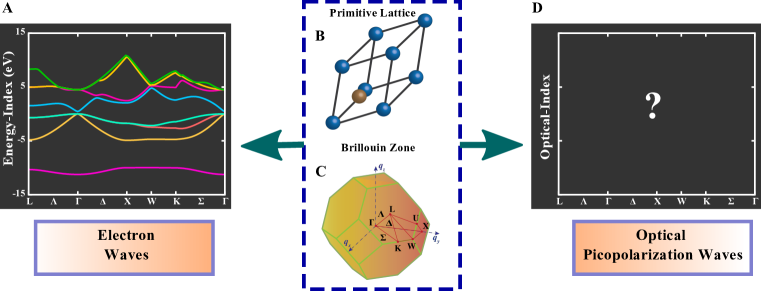
Our solution to this open problem is inspired by the band structure of electron waves in a crystal which is at the core of materials physics. It provides a foundational classification of materials based on the energy-momentum-wavefunction relationship. The electronic band structure represents the allowed energy-indices for the electron waves within the Brillouin zone of a material (Figure 1(A)). A similar band theory has also been developed for phonons which has led to considerable advances in nanoscale heat transport and thermal materials discovery [14]. In stark contrast, here we put forth the pico-optical band theory of crystalline materials which reveals hidden waves in a crystal lattice throughout the Brillouin zone (Figure 1(D)).
These picophotonic waves exist beyond the nanoscale limit and can only be unraveled using our quantum generalization of the refractive index. Specifically, in this article, we show the existence of two distinct hidden forms of waves in a crystal: a) pico-optical transverse waves, and b) pico-optical longitudinal waves. These are captured by our foundational pico-optical band theory which describes light-matter interaction at the level of crystal lattice. We unravel the pico-optical band structure and hidden waves of 14 Zinc-Blend and diamond-type cubic materials. Here, we choose Si, Ge, InAs, GaAs, CdTe, and others from Group IV, III-V, and II-VI due to their technological relevance but our framework can be easily extended to include hexagonal boron nitride, graphene, Moire materials, MoS2, etc. These optical pico-indices also capture hidden topological properties of crystalline materials such as the optical -invariant [15, 16] beyond topological invariants known from electronic band theory.
Along with building theoretical foundations, we also put forth a software package, Purdue-PicoMax, to unravel picophotonics in a wide range of 2D and 3D materials. These pico-optical bands serve as symmetry indicators beyond electronic or phononic properties and simultaneously provide a signature for identifying optical topological phases in natural materials. Purdue-PicoMax automates our theoretical framework and enables calculations of unique physical properties of 2D and 3D materials unavailable in existing light-matter interaction theories: symmetry-indicating lattice conductivity (SILC), pico-optical transverse and longitudinal picopolarization band structure. We expect Purdue-PicoMax to aid the exploration and design of materials with novel picophotonic [17] as well as pico-plasmonic phases.
It has been a long-standing challenge to understand the lattice optical polarization probed beyond static or uniform field response [18, 19, 20, 21, 22, 15]. We show that this challenge is fully addressed by our framework of the pico-optical band structure. We demonstrate that the momentum exchange processes that occur at sub-nanometer (nm) length scales in a crystal determine the lattice optical polarization. Hence, we term the lattice optical polarization arising from the quantum theory as the optical picopolarization. Recent attention has also been drawn to nonlocal optical effects that arise from modifications to the refractive index in ultra-subwavelength systems [23, 24, 25], where the non-local modification is considered in the continuum limit of hydrodynamic light-matter interaction. In stark contrast, our work focuses on crystalline symmetries that naturally occur at the atomistic level. Our results are also relevant to atomic-scale light confinements in sub-nanometre size cavities which have recently gained significant interest [26].
2 Picophotonics of Crystalline Materials
In this section, we develop the theoretical framework to unravel the pico-optical light-matter interaction of any material starting from the corresponding basic lattice parameters of a crystalline material. Our approach for obtaining optical polarization encodes the minimal coupling between the material and the gauge field , which satisfies the local U(1) gauge symmetry. Our crucial insight is that the gauge fields have to obey additional crystalline symmetries which leads to novel picophotonic light-matter interaction. We note that the central physical quantity in determining the pico-optical band structure of a material is the lattice conductivity tensor . Through a Fourier expansion in the reciprocal lattice space, we define the symmetry-indicating lattice conductivity (SILC) tensor of the form , where is the frequency, is the crystal-wavevector of the picopolarization waves, are the reciprocal lattice vectors, and the crystal-wavevector is restricted within the Brillouin zone of the material.
The lattice conductivity satisfies the invariance under space group operations (), given by
| (1) |
where, , , and is the auxiliary reciprocal lattice vector introduced to include the class of nonsymmorphic crystals. The symmetry groups of are different along different symmetry axes of the Brillouin zone, and we see from Eq. (1) that the structure of the lattice conductivity tensor is dictated by the symmetry group of (see Supplementary Material).
Our theory shows that the polarization fields in a crystal lattice form a completely orthogonal set and satisfy the Bloch form. This is in stark contrast to the conventional continuum theory used to describe the optical properties of solids [27]. We put forth the definition of the optical picopolarization waves as the eigenfunctions of the SILC for a given frequency and momentum :
| (2) |
where, represents the Cartesian outer product, is the number of pico-optical bands considered, the eigenvector , and represents the plane-wave components of the optical picopolarization wave.
We define the optical pico-indices of a crystal as the set of eigenvalues , which generalize the classical concept of the refractive index. For a given optical pico-index , we put forth the expression for the optical picopolarization wave, given by
| (3) |
Furthermore, we define the exponentially localized real-space pico-optical functions () to decompose the picopolarization waves (up to a gauge transformation),
| (4) |
where, is lattice vector in the real space. We note that our real-space pico-optical functions are analogous to Wannier functions known for the real-space representation of electronic Bloch functions. For a given frequency , the set of obtained within the Brillouin zone of the crystal describes the pico-optical band structure with being the band-index. The orthogonality of the pico-optical functions at distinct crystal lattice sites provides the foundation for the expansion of optical polarization waves. We note that, unlike the traditional electronic Wannier functions, the pico-optical functions are vectorial and represent the fluctuating optical picopolarization waves.
At the point, we notice that the space group symmetry of the crystal is preserved. However, away from the point, -symmetry group will be a subgroup of this space group. The compatibility relations between the irreducible representations of the symmetry groups at different points in the Brillouin zone determine the degeneracy pattern of the optical pico-indices , and the optical pico-indices serve as symmetry indicators. In principle, the number of pico-optical bands is infinite, however, it can be truncated to a suitably large vector. We emphasize that if we consider only a single pico-optical band (), in the zero-momentum limit, the square root of the optical-pico index () reduces to the macroscopic refractive index . Thus we retrieve the conventional optical theory as a limiting case of our picopolarization framework. In general the optical pico-indices () are complex, and the imaginary part of optical pico-indices represents the lattice extinction coefficient index.
2.1 Optical Pico-indices
In this section, we unravel the pico-optical longitudinal and transverse band structures of crystalline materials, each of which represents a distinct set of optical pico-indices. We note that an electromagnetic pulse carries a vector potential perpendicular to , and the corresponding properties of the pico-optical transverse band structure completely characterize the lattice optical response of a crystal from a light pulse. In contrast, the pico-optical longitudinal band structure governs the electrical screening properties of crystalline materials. We define the longitudinal and transverse optical picopolarization waves to satisfy the following conditions:
| (5) |
An electromagnetic pulse carries a transverse vector potential which induces the SILC component defined by the current-current correlation function. We have derived the expression for starting from the fundamental light-matter interaction Hamiltonian [17], given by
| (6) |
where, is the current density operator, is the unit vector component perpendicular to , and are the electronic Bloch functions of conduction and valence bands, is the crystal volume, and and are the electronic eigen-energy of conduction and valence bands, respectively.
The longitudinal component of the SILC provides the density-density correlation induced by a scalar potential perturbation, and the corresponding expression can be derived based on the Adler-Wiser formalism [28, 29] given by
| (7) |
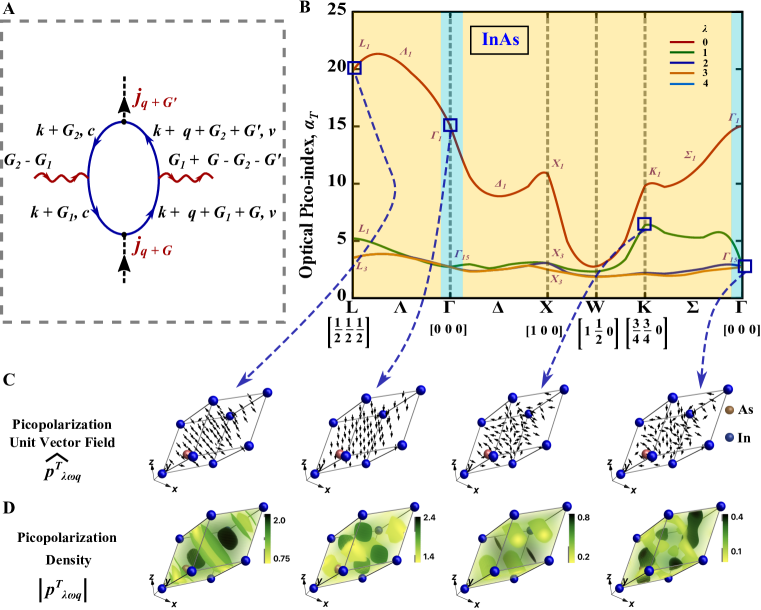
In Fig. 2(A) and Fig. 3(A), we have displayed the first-order Feynman diagrams corresponding to the transverse and longitudinal conductivity, respectively. Here, wiggly lines in the Feynman diagram represent the momentum exchange processes with the lattice. The momentum exchange processes occur at sub-nm length scales (, where is the lattice constant), and these momentum exchange processes result in the pico-optical band structure of a crystal lattice. When we neglect these momentum exchange processes, the dimension of this set reduces to unity and the optical pico-index is simply the dielectric function of the material.
Lattice Nonlocal Ohm’s Law: A distinctive feature of the optical picopolarization waves is the emergence of the lattice nonlocal Ohm’s law within a crystal lattice. Conventionally, dynamical Ohm’s law in a crystalline solid is given by , where is the cell-averaged continuum current density. However, the optical transverse picopolarization waves satisfy the lattice nonlocal Ohm’s law in a crystalline lattice, given by
| (8) |
In the continuum limit, our expression reduces to the classical form of Ohm’s law. Hence, the optical picopolarization waves generalize the classical Ohm’s law within a crystal lattice.
2.2 Picophotonic Hidden Waves
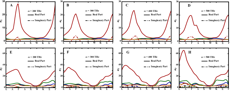
The central outcome of our analysis is the unraveling of hidden waves through our pico-optical band structure of 14 distinct Zinc-Blend and diamond-type materials. In Fig. 2(B), we use our theory to solve for the pico-optical transverse band structure in InAs at frequency THz. It is immediately revealed that there exist hidden waves deep within the crystal lattice that cannot be captured by the classical wave theory. The blue-shaded region in Fig. 2(B), represents the low momentum domain of the pico-optical band structure which recovers the classical optics. At the -point, the square root of the first optical transverse pico-index reduces to the classical refractive index, hence recovering the conventional optical theory. Furthermore, in a departure from conventional wisdom, the first optical transverse pico-index has a maximum at a momentum along the axis (Fig. 2(B)). We recognize this as a striking feature specific to the pico-optical transverse band structure arising from the ultra sub-wavelength momentum exchange processes occurring within the lattice.
In Fig. 2(C) and Fig. 2(D), we have plotted the unit vector field distribution and density of the hidden waves at THz for a few selected bands and high-symmetry points. These plots display the hidden polarization texture and crowding within the unit cell of the material. This phenomenon is beyond the classical description of light-matter interaction where polarization only varies slowly in space. We see that the first optical transverse picopolarization state around the -point (considered along direction), is aligned along the direction perpendicular to , representing the classical limit. In Fig. 2(C) and Fig. 2(D), we observe that away from the -point, the hidden waves have a considerable polarization texture and crowding at the ultra-subwavelength level. The inhomogeneous distribution of density of the optical picopolarization waves is attributed to the pico-scopic momentum exchange processes with the lattice as described earlier.
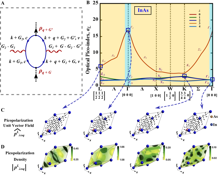
In Fig. 3(B), we plot the pico-optical longitudinal hidden waves of InAs at a given frequency THz. The pico-optical longitudinal waves determine the electronic screening properties of the material perturbed by an applied potential. We note that the hidden waves exhibit distinct temporal dynamics as they traverse through the crystal.
2.3 Purdue-PicoMax
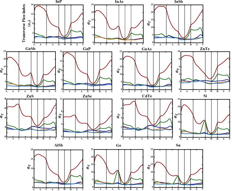
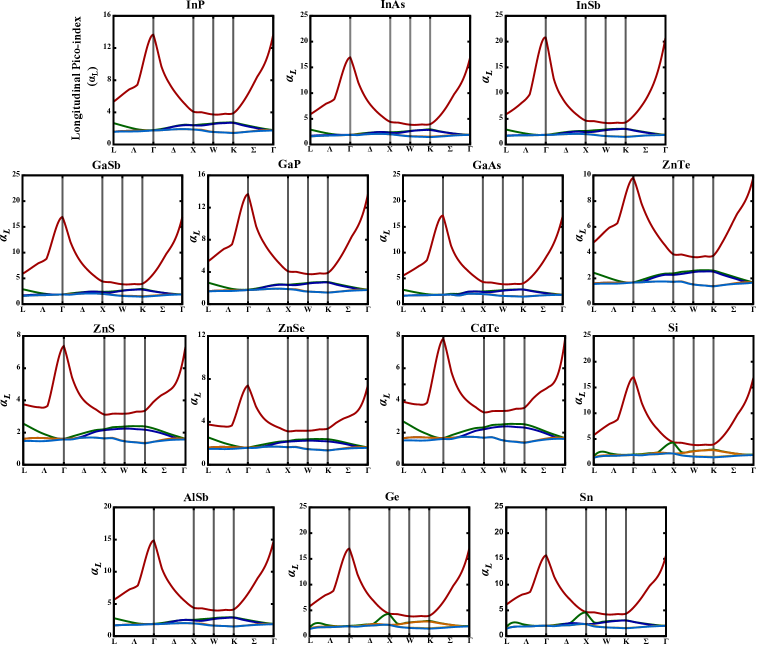
We have developed an open-source software, Purdue-PicoMax, for the community to explore the pico-optical band theory of solids. Purdue-PicoMax computes unique physical quantities arising in picophotonics. These include the symmetry-indicating lattice conductivity, pico-optical transverse and longitudinal band structure, and hidden optical waves in various materials. The development of versatile electronic structure codes such as VASP [30], Quantum ESPRESSO [31] and others, and the phonon band structure codes such as EPW [32], ABINIT [33], Perturbo [34] have revolutionized material science to design and discover novel materials with tunable electronic and phonon properties, respectively. We anticipate that the development of Purdue-PicoMax facilitates a similar acceleration towards the discovery of materials with novel pico-optical topological and electrodynamic phases of matter. Users from both the physics and material science communities can explore emerging materials for further research activities. Currently, we have included Group IV, III-V, and II–VI crystalline materials and the software can be easily adapted to include many more user-defined materials (eg: Moire materials). In Fig. 4, and Fig. 5, we have plotted the hidden waves (optical transverse and longitudinal picopolarization band structure) obtained using Purdue-PicoMax for technologically important semiconducting materials. Purdue-PicoMax is free software available on GitHub https://github.com/sathwik92/PicoMax under MIT license.
3 Discussion
We have studied topologically trivial optical materials in this study, which inherit only positive optical pico-indices. However, we note that the optical picopolarization waves hide unique topological indices such as the optical -invariant not captured by electronic band theory. We note that the SILC is precisely Green’s function of the polarization density of the material system. Following the Volovik formalism [35, 36], we obtain the topological invariant corresponding to SILC that is conserved under continuous deformations. In two dimensions, for frequencies below the bandgap, we obtain the pico-optical -invariant from the pico-optical bandstructure (see Supplementary Material), given by
| (9) |
where, is the Berry curvature of the optical picopolarization wave . From the above expression, we note that the crystals can exhibit a non-trivial pico-optical -invariant only when the optical pico-indices can be continuously deformed from positive to negative.
The pico-optical transverse band structure of a material determines the momentum direction with maximal optical response. On the other hand, the optical longitudinal picopolarization waves determine the Coulombic screening properties of the material. The pico-optical longitudinal bands also encode the multi-band plasmon dispersion [37, 38], a key signature associated with the correlated phases in materials. Plasmon frequencies for a given crystal momentum can be inferred by recognizing the maxima of the picopolarization loss function , corresponding to each optical longitudinal picopolarization band. The constant development of new near-field tools for light-matter interaction [39] makes it an exciting frontier within reach to probe these hidden waves. One can find signatures of the pico-optical longitudinal waves from coherent resonant inelastic scattering [40] or from the momentum-resolved electron energy loss experiments [41] along different crystal orientations (see Supplementary Material). The pico-optical transverse band structure can be measured via momentum-resolved Fourier transform reflectometry [42] along different crystal growth directions (see Supplementary Material).
As with the electron/phonon band theory of solids, we expect Purdue-PicoMax and the pico-optical band theory of solids to have a defining influence on our understanding of crystalline materials.
4 Methods
We determined the electronic Bloch functions and the eigen-energies by the pseudo-potential method (see Supplementary Material). Symmetry indicating lattice conductivity components are determined by Eq. (2.1) & (2.1), respectively. We performed the eigenvalue decomposition in Eq. (2) to obtain the optical pico-indices and the corresponding hidden waves. Shifted Monkhorst–Pack -points mesh of points were used in all our calculations for .
Our approach here is general and applicable to all optical frequencies and permissible momentum values throughout the Brillouin zone. As a limiting case at , the pico-optical longitudinal band structure can also be employed in chemical compounds to identify the molecular screening properties. Classically, the longitudinal polarization at a given frequency is a constant field directed along . We observe that the first optical longitudinal picopolarization wave around -point (considered along direction), is aligned along (see Fig. 3(C)), and the corresponding picopolarization density is nearly constant as shown in Fig. 3(D). Again a significant spatial texture of the optical longitudinal picopolarization is observed away from the point (Fig. 3(D)). In Fig. 3(C), we observe that the first optical longitudinal picopolarization band has a maximum at the -point and is significantly damped away from the point. This is attributed to the Coulombic screening which decays as .
We show that a key feature of the pico-optical band theory of the crystalline materials is a distinct degeneracy pattern exhibited by the optical pico-indices. The degeneracy pattern of optical picopolarization waves and the structure of SILC indicate the symmetry throughout the Brillouin zone of the material. At the point, the optical picopolarization waves adopt the point group symmetry, and the first pico-optical index at -point transforms as per the one-dimensional irreducible representation . The next four optical pico-indices belong to the irreducible representation and with degeneracy one and three, respectively. Going from the to -point, point group symmetry reduces to symmetry. The optical picopolarization waves in the class of branch out into two pico-optical bands with degeneracy two and one (see Fig. 2(B) and Fig. 3(B)). Similarly, the optical picopolarization waves throughout the Brillouin zone can be classified into a set of irreducible representations from the corresponding -symmetry group as shown in Fig. 2(B) and Fig. 3(B).
Funding This work was supported by the Office of Naval Research (ONR) under the award no. 13001334.
Disclosures The authors declare no competing interest.
Data Availability Statement Data underlying the results presented in this paper may be obtained from the authors upon reasonable request.
Supplemental document See Supplement 1 for supporting content.
References
- [1] S. Horsley and M. Woolley, “Zero-refractive-index materials and topological photonics,” \JournalTitleNature Physics 17, 348–355 (2021).
- [2] P. Chao, B. Strekha, R. Kuate Defo, et al., “Physical limits in electromagnetism,” \JournalTitleNature Reviews Physics 4, 543–559 (2022).
- [3] J. Y. Kim, H. Kim, B. H. Kim, et al., “Highly tunable refractive index visible-light metasurface from block copolymer self-assembly,” \JournalTitleNature communications 7, 12911 (2016).
- [4] F. Andreoli, M. J. Gullans, A. A. High, et al., “Maximum refractive index of an atomic medium,” \JournalTitlePhys. Rev. X 11, 011026 (2021).
- [5] H. Shim, F. Monticone, and O. D. Miller, “Fundamental limits to the refractive index of transparent optical materials,” \JournalTitleAdvanced Materials 33, 2103946 (2021).
- [6] A. Reserbat-Plantey, I. Epstein, I. Torre, et al., “Quantum nanophotonics in two-dimensional materials,” \JournalTitleAcs Photonics 8, 85–101 (2021).
- [7] A. A. Orlov, P. M. Voroshilov, P. A. Belov, and Y. S. Kivshar, “Engineered optical nonlocality in nanostructured metamaterials,” \JournalTitlePhysical Review B 84, 045424 (2011).
- [8] J. Khurgin, W.-Y. Tsai, D. P. Tsai, and G. Sun, “Landau damping and limit to field confinement and enhancement in plasmonic dimers,” \JournalTitleAcs Photonics 4, 2871–2880 (2017).
- [9] W. Yan, M. Wubs, and N. A. Mortensen, “Projected dipole model for quantum plasmonics,” \JournalTitlePhysical review letters 115, 137403 (2015).
- [10] C. R. Petersen, U. Møller, I. Kubat, et al., “Mid-infrared supercontinuum covering the 1.4–13.3 m molecular fingerprint region using ultra-high na chalcogenide step-index fibre,” \JournalTitleNature Photonics 8, 830–834 (2014).
- [11] V. R. Almeida, C. A. Barrios, R. R. Panepucci, and M. Lipson, “All-optical control of light on a silicon chip,” \JournalTitleNature 431, 1081–1084 (2004).
- [12] Z. Jacob, “Hyperbolic phonon–polaritons,” \JournalTitleNature materials 13, 1081–1083 (2014).
- [13] N. J. Halas, S. Lal, W.-S. Chang, et al., “Plasmons in strongly coupled metallic nanostructures,” \JournalTitleChemical Reviews 111, 3913–3961 (2011). PMID: 21542636.
- [14] X. Qian, J. Zhou, and G. Chen, “Phonon-engineered extreme thermal conductivity materials,” \JournalTitleNature Materials 20, 1188–1202 (2021).
- [15] T. Van Mechelen, S. Bharadwaj, Z. Jacob, and R.-J. Slager, “Optical -insulators: Topological obstructions to optical wannier functions in the atomistic susceptibility tensor,” \JournalTitlePhys. Rev. Res. 4, 023011 (2022).
- [16] W. Sun, T. Van Mechelen, S. Bharadwaj, et al., “Optical n-plasmon: topological hydrodynamic excitations in graphene from repulsive hall viscosity,” \JournalTitleNew Journal of Physics 25, 113009 (2023).
- [17] S. Bharadwaj, T. Van Mechelen, and Z. Jacob, “Picophotonics: Anomalous atomistic waves in silicon,” \JournalTitlePhys. Rev. Appl. 18, 044065 (2022).
- [18] P. T. Mahon and J. E. Sipe, “Electric polarization and magnetization in metals,” \JournalTitleSciPost Phys. 14, 058 (2023).
- [19] N. Talebi, “Electron-light interactions beyond the adiabatic approximation: recoil engineering and spectral interferometry,” \JournalTitleAdvances in Physics: X 3, 1499438 (2018).
- [20] B. Wunsch, T. Stauber, F. Sols, and F. Guinea, “Dynamical polarization of graphene at finite doping,” \JournalTitleNew Journal of Physics 8, 318 (2006).
- [21] A. J. Misquitta and A. J. Stone, “Distributed polarizabilities obtained using a constrained density-fitting algorithm,” \JournalTitleThe Journal of chemical physics 124 (2006).
- [22] V. A. Markel, “Introduction to the maxwell garnett approximation: tutorial,” \JournalTitleJOSA A 33, 1244–1256 (2016).
- [23] Y. Yang, D. Zhu, W. Yan, et al., “A general theoretical and experimental framework for nanoscale electromagnetism,” \JournalTitleNature 576, 248–252 (2019).
- [24] J. J. Baumberg, J. Aizpurua, M. H. Mikkelsen, and D. R. Smith, “Extreme nanophotonics from ultrathin metallic gaps,” \JournalTitleNature materials 18, 668–678 (2019).
- [25] P. Gonçalves, T. Christensen, N. Rivera, et al., “Plasmon–emitter interactions at the nanoscale,” \JournalTitleNature communications 11, 366 (2020).
- [26] A. N. Babar, T. A. S. Weis, K. Tsoukalas, et al., “Self-assembled photonic cavities with atomic-scale confinement,” \JournalTitleNature 624, 57–63 (2023).
- [27] G. Ermolaev, D. Grudinin, Y. Stebunov, et al., “Giant optical anisotropy in transition metal dichalcogenides for next-generation photonics,” \JournalTitleNature communications 12, 854 (2021).
- [28] S. L. Adler, “Quantum theory of the dielectric constant in real solids,” \JournalTitlePhys. Rev. 126, 413–420 (1962).
- [29] N. Wiser, “Dielectric constant with local field effects included,” \JournalTitlePhys. Rev. 129, 62–69 (1963).
- [30] J. Hafner, “Ab-initio simulations of materials using vasp: Density-functional theory and beyond,” \JournalTitleJournal of computational chemistry 29, 2044–2078 (2008).
- [31] I. Carnimeo, F. Affinito, S. Baroni, et al., “Quantum espresso: One further step toward the exascale,” \JournalTitleJournal of Chemical Theory and Computation (2023).
- [32] H. Lee, S. Poncé, K. Bushick, et al., “Electron-phonon physics from first principles using the epw code,” \JournalTitlearXiv preprint arXiv:2302.08085 (2023).
- [33] X. Gonze, B. Amadon, G. Antonius, et al., “The abinit project: Impact, environment and recent developments,” \JournalTitleComputer Physics Communications 248, 107042 (2020).
- [34] J.-J. Zhou, J. Park, I.-T. Lu, et al., “Perturbo: A software package for ab initio electron–phonon interactions, charge transport and ultrafast dynamics,” \JournalTitleComputer Physics Communications 264, 107970 (2021).
- [35] G. E. Volovik, The universe in a helium droplet, vol. 117 (OUP Oxford, 2003).
- [36] Z. Wang and S.-C. Zhang, “Strongly correlated topological superconductors and topological phase transitions via green’s function,” \JournalTitlePhys. Rev. B 86, 165116 (2012).
- [37] M. Papaj and C. Lewandowski, “Probing correlated states with plasmons,” \JournalTitleScience Advances 9, eadg3262 (2023).
- [38] A. A. Husain, E. W. Huang, M. Mitrano, et al., “Pines’ demon observed as a 3d acoustic plasmon in sr2ruo4,” \JournalTitleNature pp. 1–5 (2023).
- [39] F. J. Garcia de Abajo and V. Di Giulio, “Optical excitations with electron beams: Challenges and opportunities,” \JournalTitleACS photonics 8, 945–974 (2021).
- [40] W. Schülke, Electron dynamics by inelastic X-ray scattering, vol. 7 (OUP Oxford, 2007).
- [41] Z. Poursoti, W. Sun, S. Bharadwaj, et al., “Deep ultra-violet plasmonics: exploiting momentum-resolved electron energy loss spectroscopy to probe germanium,” \JournalTitleOptics Express 30, 12630–12638 (2022).
- [42] R. A. DeCrescent, N. R. Venkatesan, C. J. Dahlman, et al., “Bright magnetic dipole radiation from two-dimensional lead-halide perovskites,” \JournalTitleScience advances 6, eaay4900 (2020).
Unraveling Picophotonics of Crystalline Materials: Supplementary Material
1 Symmetry Indicated Lattice Conductivity (SILC)
Lattice conductivity in a crystal satisfies the translational invariance of the form
| (10) |
where, is the translation vector in real space. Hence, we can expand in the reciprocal lattice basis as
| (11) |
where, is the crystal volume. In a crystal, lattice conductivity also satisfies the invariance under space group operations (), given by
| (12) |
where, the nonprimitive translation vector is introduced to include the class of nonsymmorphic crystals. In the reciprocal lattice space, the space group operations imply the condition
| (13) |
where, , , and is the auxiliary reciprocal lattice vector. The reality condition dictates that
| (14) |
Hence, the lattice conductivity of a crystalline material is symmetry indicating, and the structure of the lattice conductivity is determined by the space group symmetry for a given crystal momentum . This relation implies that the lattice optical response in solids belongs to the universality class- of real bosons. In topological superconductors, this is typically referred to as the particle-hole -symmetry. -symmetry is an exact symmetry in the lattice optical response, however only an approximate in superconductors.
The space-group symmetry dictated by within the crystal lattice determines the structure of the lattice conductivity, and the corresponding symmetry transformation is given in Eq. 13. In zinc-blend materials, at -point, the symmetry group is . The point group has elements and the degree of degeneracy for the optical picopolarization modes can be up to three as per the irreducible representations. In our calculations, we have considered nine vectors to result in a nine-dimensional tensor for the lattice conductivity. Let us consider, in units of . Through symmetry transformations, we obtain 9 independent components in the conductivity tensor and the corresponding expression is given by
| (15) |
At -point, the point group symmetry results in 18 independent components in the conductivity tensor, given by
| (16) |
A similar analysis is performed for the -symmetry groups over the entire Brillouin zone to obtain the optical lattice conductivity tensor and the corresponding picopolarization modes. Diamond crystal lattice belongs to the nonsymmorphic space group, and the symmetry considerations are distinct from the zinc-blend materials. Especially at -point, symmetry considerations allow only double-degenerate hidden optical picopolarization waves (as shown in Fig. 4 and Fig. 5 of the main text) for Si, Ge, and Sn.
1.1 Empirical Pseudopotential Method for Electronic band structure
Energy eigenvalues and the wavefunctions corresponding to the electronic band structure are required to calculate . We obtain the electronic band structure based on the empirical pseudopotential method. Hamiltonian of a solid within this framework is given by
| (17) |
where, are reciprocal lattice vectors, is the electronic wavevector, is the local pseudopotential and is the nonlocal pseudopotential.
1.2 Experimental Detection of Pico-optical Band Structure
In this section, we discuss the experimental considerations for the observation of the pico-optical band structure discussed in this work. The pico-optical longitudinal band structure can be inferred from the coherent resonant inelastic scattering [40] or momentum-resolved electron energy loss experiments [41] along different crystal orientations by determining the double differential cross-section. Since the inelastic scattering experiments involve a two-photon process, from the Kramers–Heisenberg formula, we see that contributions from the term in the interaction Hamiltonian has the most dominant contribution. Hence, provides a pathway to measure the pico-optical longitudinal band structure. The key quantity to obtain in these measurements is the lattice nonlocal structure factor, defined as
| (18) |
In a coherent resonant inelastic scattering experiment, an incoming field with wavevector is incident on the sample and both the Bragg reflected field with wavevector , and scattered field with wavevector can be measured. From the Bragg condition, we obtain , and from the scattered field we can obtain . The lattice nonlocal structure factor can be obtained with the measurement of double differential cross-section. Hence, one can experimentally obtain the full lattice conductivity at a given frequency, and further resolve the pico-optical longitudinal band structure.
The pico-optical transverse band structure can be measured via momentum-resolved Fourier transform reflectometry [42] along different crystal growth directions. The angle-dependent study provides a tool to tune the wavevector along high-symmetry directions of the Brillouin zone. The incident field generates the current-current correlation and the measured reflectance spectra can be used to obtain the optical pico-index . A detailed analysis of the consequences of such measurements will be considered in future work.
2 Topological Invariant for Pico-optical Band Theory of Solids
The symmetry indicating lattice conductivity can be thought of as a Green’s function of the system. Hence, we are interested in obtaining the topological invariant corresponding to SILC. For simplicity here we consider a 2+1D system. Following a familiar recipe from the topological band theory, the optical topological invariant corresponding to a continuous deformation of SILC is given by:
| (19) |
where, is the frequency analytically continued to the complex plane. Following the procedure of Wang and Zhang [36], we can circumvent the integral over the complex frequency space by expressing the above topological invariant in terms of the pico-optical band structure parameters. We obtain the expression:
| (20) |
where is the Berry curvature of the optical picopolarization wave , given by
| (21) |
The total Berry curvature and hence the optical topological invariant only when the optical pico-indices can be continuously deformed from positive to negative.