Scalable, high-fidelity all-electronic control of trapped-ion qubits
Abstract
The central challenge of quantum computing is implementing high-fidelity quantum gates at scale. However, many existing approaches to qubit control suffer from a scale-performance trade-off, impeding progress towards the creation of useful devices. Here, we present a vision for an electronically controlled trapped-ion quantum computer that alleviates this bottleneck. Our architecture utilizes shared current-carrying traces and local tuning electrodes in a microfabricated chip to perform quantum gates with low noise and crosstalk regardless of device size. To verify our approach, we experimentally demonstrate low-noise site-selective single- and two-qubit gates in a seven-zone ion trap that can control up to 10 qubits. We implement electronic single-qubit gates with fidelity, and demonstrate consistent performance with low crosstalk across the device. We also electronically generate two-qubit maximally entangled states with fidelity and long-term stable performance over continuous system operation. These state-of-the-art results validate the path to directly scaling these techniques to large-scale quantum computers based on electronically controlled trapped-ion qubits.
I Introduction
The last three decades have brought about impressive demonstrations of key building blocks of quantum computers (QCs). Recent proof-of-principle experiments have shown that quantum gates on physical qubits can be implemented with high fidelity Harty et al. (2014); Clark et al. (2021); Ding et al. (2023), and that quantum error correction can be used to improve error rates Acharya et al. (2023); da Silva et al. (2024). Scaling to larger system sizes has been demonstrated for some platforms King et al. (2023); Kim et al. (2023); Bluvstein et al. (2024); Manetsch et al. (2024), as have methods for scaling using quantum interconnects Moehring et al. (2007); Mills et al. (2019); Zhong et al. (2019); Stephenson et al. (2020) and integrated control Mehta et al. (2014, 2020); Niffenegger et al. (2020); Zwerver et al. (2022). However, to build useful QCs, it is necessary to develop architectures that are simultaneously low-noise and scalable. This requires co-optimizing the performance metrics - such as fidelity, connectivity, selectivity, and parallelism – with the scalability metrics – including manufacturability, qubit variability, footprint, signal delivery, and power consumption.
Chip-scale trapped-ion quantum computers (TIQCs) – with atomic qubits suspended above a control chip Chiaverini et al. (2005) – have the potential to satisfy these criteria by combining the low-noise performance of atomic qubits Sepiol et al. (2019) with the scalability of chip-integrated electronics. While TIQCs are, by many metrics, the best-performing QC systems today Moses et al. (2023), existing commercial systems are difficult to scale to useful sizes, as they rely on free-space light delivery to enable laser-based gates. Despite promising proof-of-principle demonstrations of laser-based gates with integrated photonics Mehta et al. (2016, 2020), significant performance, manufacturability, footprint, signal delivery, and power consumption challenges associated with integrated light generation, modulation, and distribution remain to be overcome Mordini et al. (2024); Kwon et al. (2024); Hogle et al. (2023).
An alternative method is to perform quantum gates using magnetic fields generated by chip-integrated traces Ospelkaus et al. (2008). This approach is immediately compatible with commercial microfabrication processes, opening the door to full device integration and scalability. Nevertheless, while previous work demonstrated high-quality single- and two-qubit laser-free gates Harty et al. (2014); Srinivas et al. (2021); Weber et al. (2024), the possibility of using this approach to build universal, integrated, multi-zone TIQCs remained unexplored so far.
In this paper, we propose an all-electronic TIQC architecture that combines laser-free gates with local electric-field tuning for high-performance integrated control. To validate our vision, we demonstrate the ability to perform all-electronic single- and two-qubit gates with state-of-the-art fidelities across a multi-zone microfabricated ion trap. We further show that electrical tuning allows for highly flexible, low-crosstalk coherent control. Our results validate the path to high-performance, integrated, large-scale QCs manufactured using established foundry processes.
II Architecture
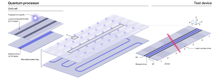
Our all-electronic architecture for coherent control of trapped-ion qubits is illustrated in Fig. 1. It employs a chip ion trap Chiaverini et al. (2005), where voltages applied to electrodes on the top metal layer hold ion qubits tens of microns above the surface. Building on previous proposals and demonstrations of addressed laser-free quantum gates Leibfried et al. (2007); Warring et al. (2013a); Lekitsch et al. (2017); Srinivas et al. (2021), two elements are incorporated into the chip to achieve site-selective control. First, a shared drive (Fig. 1, purple) is used to deliver a control field globally to all qubits at once Leibfried et al. (2007). Second, local tuning electrodes (Fig. 1, blue) are used to tune the control Hamiltonian on a per-zone basis, allowing for site-selective operations Seck et al. (2020); Srinivas et al. (2023); Sutherland et al. (2023).
The shared drive is implemented by passing oscillating (AC) currents through traces defined inside the chip. These AC currents generate AC magnetic fields at all sites, which form the basis of single- and multi-qubit quantum gates Warring et al. (2013b); Sutherland et al. (2019). To ensure efficient power and I/O use, traces generating magnetic fields in different zones are wired in series to a single source Srinivas et al. (2021); Enthoven et al. (2024). Local tuning is implemented by applying additional DC voltages to the top-layer electrodes. These voltages generate electric fields that adjust the ion positions; as the on-chip currents generate large magnetic field gradients in the near field of the chip, even small changes in ion positions result in significant variations in the magnetic fields they experience Wineland et al. (1998); Mintert and Wunderlich (2001). The voltages can also generate electric field curvatures that adjust ion motional frequencies. As shown experimentally in section III, these degrees of freedom can be used to locally modulate the strength of single- and multi-qubit interactions.
The combination of the shared AC magnetic drive and local DC electric tuning allows coherent control with high fidelity, site selectivity, and parallelism. For example, to perform quantum operations globally (all qubits “active”), the local electrodes are used to fine-tune small differences in the coupling rates between qubits and the magnetic drive such as to make the interaction Hamiltonians identical for all zones. Site-selectivity can then be achieved by using the local electrodes to “hide” qubits in certain zones such as to make their interaction Hamiltonian close to the identity Warring et al. (2013a); Leu et al. (2023); Lysne et al. (2024). Finally, local electrodes can continuously tune the Hamiltonian between the “active” and the “hidden” values to perform different operations in different zones in parallel.
Compared to existing architectures for TIQC which use local laser and/or magnetic drives Steane (2006); Lekitsch et al. (2017), our architecture brings several performance and scalability benefits. First, all qubit tuning is achieved using DC voltages, which can be efficiently multiplexed using only standard chip-integrated electronics Malinowski et al. (2023). This alleviates the chip manufacturability and wiring challenges, allowing the use of standard microfabrication and packaging processes. Furthermore, DC voltages can be distributed across a chip with negligible crosstalk and power dissipation, and the electric-field patterns from multiple electrodes can be well localized to specific trap zones. Finally, our method does not require new dedicated structures, instead repurposing the electrodes already present in the TIQC for qubit shuttling and stray-field compensation.
Second, all coherent control is achieved using electric and magnetic fields, which can be generated from electronically integrated, high-stability, low-cost sources with low phase and amplitude noise Ball et al. (2016). This is in contrast to laser-based gates, which typically rely on large, complex, free-space optical sources. Furthermore, while laser-based gates face stringent fidelity limits due to spontaneous emission Ozeri et al. (2007); Moore et al. (2023), laser-free gates have a negligible fundamental noise floor Sutherland et al. (2022); Srinivas et al. (2021), allowing significant fidelity improvements through hardware engineering alone. Finally, wiring the shared drive in series is highly power-efficient, allowing the number of qubits to be increased while keeping the power density constant.
To verify the performance of our architecture, we have designed and built a seven-zone microfabricated ion trap with local DC electrodes and a shared AC current-carrying trace. In the subsequent section, we demonstrate that all-electronic control can be used to perform single- and two-qubit gates in a site-selective fashion. Furthermore, we show the low-noise capabilities of our technology by benchmarking single-qubit gates with fidelity, and by creating two-qubit maximally entangled states with fidelity – to our knowledge, record-level performance for any QC platform to date. Finally, we discuss the path to scaling this performance to mid-scale QCs with thousands of qubits.
III Experiments
The architecture validation experiments are performed in a seven-zone single-layer linear microfabricated trap cooled to K (Fig. 1c). Each zone contains independent electrodes over µm along which act as local tuners, and a current-carrying trace routed in the center of the chip acts as the shared drive. The qubit states and are encoded in the Zeeman sublevels of ions trapped above the chip surface. The qubit frequency MHz is set by a static magnetic field of mT, aligned in the plane of the chip perpendicular to the trap axis. Laser beams at 375 nm, 397 nm, 423 nm, 729 nm, 854 nm, and 866 nm are aligned above the central zone to facilitate ion loading, cooling, qubit initialization and measurement; in all other zones, all ion control is laser-free.
Each experimental shot begins with Doppler and sideband cooling one or two “probe” ions to near the motional ground state Metcalf and van der Straten (2003). The ions are then transported using time-dependent voltages on the DC electrodes to the center of the zone to be probed, and electrodes in all zones are set to initialize potential wells capable of holding ions. Following that, local electrode DC voltages are adjusted to selectively activate interactions in some zones only, and a sequence of AC current pulses, near-resonant with the qubit transition, is applied to the shared trace to drive the desired operation. Subsequently, the probe ion(s) are shuttled back to the central zone, state is shelved using a sequence of 729 nm pulses, and state-dependent fluorescence is collected on a CMOS camera to measure the qubit state Burrell et al. (2010). In the experiments presented below, single-qubit gates are performed in all 7 trap zones, while two-qubit gates are only performed in zones 2–6 due to a reduced tuning electrode count in zones 1 and 7. The gates are benchmarked on stationary qubits, probing one zone at a time.
III.1 High-fidelity tunable single-qubit gates
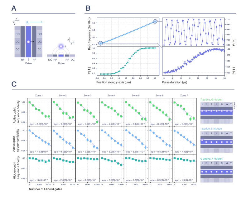
Consider a qubit with frequency in zone (Fig. 2a). Applying an oscillating current for duration through the shared trace results in a single-qubit rotation unitary , where , are the Pauli spin matrices, and the gate angle , where the Rabi frequency depends on the magnitude and polarization of the magnetic field from the shared trace (see appendix A). In our geometry, is proportional to the -polarized component of the magnetic field . To achieve site-selective control, we leverage the fact that directly above the shared trace while remains significant (Fig 2a). Thus, zone-selective ion translation along results in zone-selective adjustment of .
To validate the method, we measure the Rabi frequency for a range of ion positions in the central zone. The results are summarized in Fig. 2b. At mA, we find that we can tune the Rabi frequency between kHz and kHz by translating an ion from µm (qubit “hidden”) to µm (qubit “active”). This translation is performed by tuning voltages on local electrodes by V. We correct for the effect of the residual Rabi frequency at the “hidden” position (caused by deg misalignment of the static magnetic field) by employing a Solovay-Kitaev-1 gate sequence, which uses three resonant pulses to improve robustness to static Rabi frequency errors Merrill and Brown (2012). As shown in Fig. 2b for a total gate duration of , we can switch between (qubit “hidden”) and (qubit “active”) with high contrast and high degree of robustness against ion position errors.
We quantify the gate errors using single-qubit randomized benchmarking (RB) Knill et al. (2008); Magesan et al. (2011) with all zones set to “active”, shown in Fig 2c (top) and described further in appendix A. Using all-electronic control, we achieve an average error of per Clifford, consistent across all 7 zones, and in agreement with independently measured noise in the signal delivery chain. This is, to our knowledge, the lowest single-qubit gate error ever recorded in a multi-zone quantum processor.
To estimate the crosstalk errors, we repeat RB with one qubit “active” at a time (Fig 2c, middle). The resulting error per Clifford of is unchanged within measurement uncertainty, indicating that “hiding” or “activating” other qubits changes target qubit gate errors by . A more dominant source of crosstalk is the residual magnetic interaction between the shared drive and the “hidden” qubits. To estimate its magnitude, we record the effect of RB on “hidden” qubits (Fig 2c, bottom), finding a spin flip probability of per Clifford, once again indicating very low crosstalk. The remaining error on the “hidden” qubits is dominated by coherent effects and can be suppressed with higher-order composite pulses Merrill and Brown (2012).
III.2 High-fidelity tunable two-qubit gates
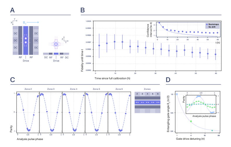
Consider a pair of qubits with frequency and a motional mode frequency in zone (Fig. 3a). Applying a bichromatic oscillating current for duration to the shared trace results in a two-qubit entangling unitary as long as , where is an integer Sørensen and Mølmer (1999); Ospelkaus et al. (2008) (see appendix B). The entangling gate angle is then given by , where the gate Rabi frequency depends on the magnitude of the magnetic field gradient along the direction of ion motion Ospelkaus et al. (2008).
To implement arbitrary quantum computation, it suffices to complement site-selective tunable single-qubit rotations with global maximally-entangling two-qubit gates (). We demonstrate this capability by preparing maximally entangled states as follows. We optically pump two ions to initial state and set the radial rocking mode to be at a frequency MHz and aligned in the plane of the chip. We then apply a sequence of two bichromatic AC current pulses through the shared trace, each with A and kHz, resulting in kHz. Each pulse has a duration of , and we flip the phase difference between the currents by between the pulses to improve robustness to fluctuations in Hayes et al. (2012). This sequence ideally prepares a maximally entangled state . We estimate the fidelity with that state by measuring the qubit populations at the end of the pulse, as well as parity contrast after an additional “analysis” pulse with a variable phase Leibfried et al. (2003).
We begin the experiments by roughly tuning the two-qubit interactions throughout the trap. By electrically matching mode frequencies and orientations of all five two-qubit wells simultaneously, we generate maximally entangled states in every zone with error rate (Fig. 3c), and we observe no statistically meaningful zone-to-zone variations. To characterize the gate performance with high precision, we then perform fine parameter calibration in zone 4 and repeat the measurement sequence over hours to estimate the fidelity with a statistical uncertainty of . The results are shown in Fig. 3b. Averaging over all data points, we find the error of preparing a maximally entangled state of , a record for any QC platform. The uncertainty corresponds to a 68% confidence interval estimated via bootstrapping Efron and Tibshirani (1994), and the fidelity estimate has been corrected for the state preparation error of and the measurement error of which were independently monitored throughout the data acquisition period (see appendix B for details).
To benchmark the baseline passive stability of the system, we continued the data acquisition for a further 48 hours, bringing the total number of experimental runs to . We find that, beyond hours, the uncertainty in the error deviates from the scaling expected for purely statistical fluctuations (Fig. 3d, inset), indicating a fidelity drift. Nonetheless, even when averaged over the full hours of data acquisition, we record an error of , state-of-the-art for any QC platform. The average fidelity drift rate is at the level of per day over the full data run. During that period, only the motional frequency was regularly calibrated using an automated routine, with all other system parameters, including the qubit frequency, fixed at the initial calibration value.
Based on independent memory benchmarking experiments O’Malley et al. (2015); Sepiol et al. (2019), we estimate that the majority of the remaining infidelity can be accounted for by qubit frequency fluctuations. At the same time, analysis of population errors in the experiments above, as well as independent measurements of mode heating rates ( phonon per second on the gate motional mode), allow us to upper-bound the combined error of motional mode fluctuations and heating to . These results suggest that the entangling operation error rate can be reduced to by employing standard techniques to protect from qubit dephasing, such as dynamical decoupling Viola and Lloyd (1998); Bermudez et al. (2012); Harty et al. (2016); Weber et al. (2024) and/or field-insensitive encodings Langer et al. (2005). Simultaneously, the high level of stability in the fidelity measurements indicates that the errors caused by parameter drifts can be also kept to by adding only sparse calibration routines, e.g. one additional automated calibration per gate parameter per day. Together, these results show a direct path to reliable and robust quantum control with two-qubit gate error rates .
Finally, we note that while the experiments above focussed on the maximally entangling operations, the method can be extended to implement tunable-angle two-qubit operations. We demonstrate this experimentally by electrically adjusting the potential experienced by the ions to offset the motional frequency by from the shared drive. We then apply the same current pulse as above through the shared trace, and measure the contrast of qubit parity oscillations to estimate the entangling area . In Fig. 3d we show that this allows for the entangling area to be adjusted in discrete steps as . We note that further continuous control over is possible by adjusting the mode orientation and that the two-qubit interactions can be fully switched off () by splitting the ion crystal before the shared drive is turned on. Such tunable-angle two-qubit gates could be used for further error reduction through more efficient unitary decomposition Parra-Rodriguez et al. (2020); Foxen et al. (2020); Lacroix et al. (2020).
IV Discussion
The experiments presented in section III demonstrate that the all-electronic control architecture discussed in section II allows for low-noise, site-selective multi-zone control of trapped-ion qubits. Here, we outline how these primitives can be combined with established ion-trap and microfabrication technology to build next-generation high-performance QCs with many thousands of qubits. These mid-scale QCs are expected to provide early computational value Clinton et al. (2024), while simultaneously serving as architectural proof-points for large-scale fault-tolerant QCs.
We envision the all-electronic control architecture to be at the core of the TIQC built on a microfabricated multi-layer silicon chip Guise et al. (2015). Following the QCCD approach Wineland et al. (1998), the unit cells will be arranged on a 2D grid as in Fig. 1, with junctions placed throughout the device to facilitate all-to-all connectivity via ion shuttling Burton et al. (2023). To minimize qubit frequency variations across the chip, the device will be placed in a highly homogeneous magnetic field, and quantum information will be encoded into atomic states with reduced magnetic-field sensitivity Langer et al. (2005).
Qubit state preparation and measurement (SPAM) will be achieved using laser light, delivered from off-chip sources using chip-integrated photonics Mehta et al. (2020); Niffenegger et al. (2020); Ivory et al. (2021). We propose to implement all SPAM using shared laser drives only, delivering light to all unit cells simultaneously, and once again using local electrodes to fine-tune the operations by moving ions in and out of laser beams. This alleviates the need for building optical systems for large-scale delivery of individually modulated laser beams, historically a major roadblock to scaling laser-based TIQCs Wang et al. (2020); Shih et al. (2021); Pogorelov et al. (2021); Binai-Motlagh et al. (2023); Sotirova et al. (2023). Furthermore, SPAM requires orders of magnitude less optical power than high-fidelity coherent optical operations Ospelkaus et al. (2011), relaxing constraints on optical losses and beam quality. Thus, our photonic delivery network can be built out of purely passive integrated components (waveguides, splitters, and grating couplers) Mehta and Ram (2017), and using only processes and materials that are well known to the semiconductor industry Mehta et al. (2016); West et al. (2019).
We envision that, using all-electronic control primitives, ever larger QCs can be built by repeating more and more unit cells. Assuming a zone spacing of µm as in section III, a 10,000-qubit device only requires a chip area of , comparable to a typical camera sensor. Power dissipation from the shared trace will be minimized by placing it on a dedicated low-loss metal layer and keeping the chip at cryogenic temperatures. For example, a shared trace of 50 µm width, 2 µm thickness, and m resistivity Sambles et al. (1981) carrying a current of 1 A would lead to power dissipation of 0.35 mW per cell, allowing a chip with tens of thousands of qubits to be operated in an off-the-shelf 4 K cryostat, and with further order-of-magnitude gains possible by reducing the ion-electrode distance.
Brute-force device scaling could be limited by the practical wiring limits of purely passive devices. However, as argued in recent theoretical Malinowski et al. (2023) and experimental Delaney et al. (2024) work, most control electrodes can be co-wired across the device, such that a modest number () of analog voltage inputs suffices to achieve all-to-all connectivity regardless of device size. Furthermore, due to their low bandwidth, the local tuning electrodes can be efficiently multiplexed using only simple, cryogenically compatible, low-power chip-scale electronics Malinowski et al. (2023). This allows hundreds of electrodes to be controlled from a single analog input. By employing these two methods, a few hundred input lines – a typical number of analog signals in today’s TIQCs – can already control devices with tens of thousands of qubits.
Practical QC manufacturing also requires careful design tolerancing and efficient device calibration, as cell-to-cell variations can have catastrophic effects on device performance and yield Hertzberg et al. (2021); Berke et al. (2022). Compared to many QC modalities, the all-electronic TIQC architecture poses minimal new demands on the chip design, tolerancing, and manufacturing processes. In contrast to solid-state qubits, trapped-ion qubits leverage the physical separation between the qubit and the chip to suppress the detrimental effects of surface and material disorder on gate performance de Leon et al. (2021). The experiments presented in section III allow us to upper-bound the two-qubit gate error from surface-induced motional dephasing to less than , and further gains can be achieved by employing coherent control Hayes et al. (2012) and surface treatment techniques Allcock et al. (2011); Hite et al. (2012); Brown et al. (2021); Berlin-Udi et al. (2022).
Given that TIQCs allow for low surface noise and high qubit frequency uniformity, the primary goal of QC tolerancing and calibration is to equalize the control field parameters in different unit cells. Notably, the on-chip electronic control elements – the shared trace and the local electrodes – have typical minimum size scales of tens of microns, several orders of magnitude larger than the resolution of modern semiconductor processes. Thus, large-scale highly uniform fabrication of multi-layer qubit control structures is relatively straightforward. While integrated photonics requires sub-micron dielectric features Beck et al. (2024), their uniformity needs can be considerably relaxed by carrying out dissipative operation in the saturated steady-state regime Lin et al. (2013); Cole et al. (2022); Malinowski et al. (2022). Finally, the qubit coupling inhomogeneities caused by residual chip manufacturing and design imperfections can be shimmed out using local tuning electrodes. The combination of low calibration complexity, high parameter stability (section III), and the ability to parallelize calibrations in different zones will allow continuous TIQC operation with minimal downtime.
In summary, we have presented a vision for TIQCs based on all-electronic coherent control to alleviate the scale and performance challenges of today’s QCs. We have experimentally tested the fundamental control primitives of our architecture – site-selective single- and two-qubit gates – and verified that both can be implemented with state-of-the-art fidelities. We have discussed the prospects for scaling these systems up, and argued that next-generation devices with thousands of qubits can be fabricated using only established microfabrication technology. This shows the path to increasing QC size without sacrificing performance, enabling mid- and large-scale QCs that can solve problems of commercial and scientific importance.
Acknowledgements
We thank the entire Oxford Ionics team for their contributions to this work. We also thank Daniel Slichter and Mario Gely for their helpful comments on an earlier version of the manuscript.
References
- Harty et al. (2014) T. P. Harty, D. T. C. Allcock, C. J. Ballance, L. Guidoni, H. A. Janacek, N. M. Linke, D. N. Stacey, and D. M. Lucas, Physical Review Letters 113, 220501 (2014).
- Clark et al. (2021) C. R. Clark, H. N. Tinkey, B. C. Sawyer, A. M. Meier, K. A. Burkhardt, C. M. Seck, C. M. Shappert, N. D. Guise, C. E. Volin, S. D. Fallek, H. T. Hayden, W. G. Rellergert, and K. R. Brown, Physical Review Letters 127, 130505 (2021).
- Ding et al. (2023) L. Ding, M. Hays, Y. Sung, B. Kannan, J. An, A. Di Paolo, A. H. Karamlou, T. M. Hazard, K. Azar, D. K. Kim, B. M. Niedzielski, A. Melville, M. E. Schwartz, J. L. Yoder, T. P. Orlando, S. Gustavsson, J. A. Grover, K. Serniak, and W. D. Oliver, Physical Review X 13, 031035 (2023).
- Acharya et al. (2023) R. Acharya, I. Aleiner, R. Allen, T. I. Andersen, M. Ansmann, F. Arute, K. Arya, A. Asfaw, J. Atalaya, R. Babbush, D. Bacon, J. C. Bardin, J. Basso, A. Bengtsson, S. Boixo, G. Bortoli, A. Bourassa, J. Bovaird, L. Brill, M. Broughton, B. B. Buckley, D. A. Buell, T. Burger, B. Burkett, N. Bushnell, Y. Chen, Z. Chen, B. Chiaro, J. Cogan, R. Collins, P. Conner, W. Courtney, A. L. Crook, B. Curtin, D. M. Debroy, A. Del Toro Barba, S. Demura, A. Dunsworth, D. Eppens, C. Erickson, L. Faoro, E. Farhi, R. Fatemi, L. Flores Burgos, E. Forati, A. G. Fowler, B. Foxen, W. Giang, C. Gidney, D. Gilboa, M. Giustina, A. Grajales Dau, J. A. Gross, S. Habegger, M. C. Hamilton, M. P. Harrigan, S. D. Harrington, O. Higgott, J. Hilton, M. Hoffmann, S. Hong, T. Huang, A. Huff, W. J. Huggins, L. B. Ioffe, S. V. Isakov, J. Iveland, E. Jeffrey, Z. Jiang, C. Jones, P. Juhas, D. Kafri, K. Kechedzhi, J. Kelly, T. Khattar, M. Khezri, M. Kieferová, S. Kim, A. Kitaev, P. V. Klimov, A. R. Klots, A. N. Korotkov, F. Kostritsa, J. M. Kreikebaum, D. Landhuis, P. Laptev, K.-M. Lau, L. Laws, J. Lee, K. Lee, B. J. Lester, A. Lill, W. Liu, A. Locharla, E. Lucero, F. D. Malone, J. Marshall, O. Martin, J. R. McClean, T. McCourt, M. McEwen, A. Megrant, B. Meurer Costa, X. Mi, K. C. Miao, M. Mohseni, S. Montazeri, A. Morvan, E. Mount, W. Mruczkiewicz, O. Naaman, M. Neeley, C. Neill, A. Nersisyan, H. Neven, M. Newman, J. H. Ng, A. Nguyen, M. Nguyen, M. Y. Niu, T. E. O’Brien, A. Opremcak, J. Platt, A. Petukhov, R. Potter, L. P. Pryadko, C. Quintana, P. Roushan, N. C. Rubin, N. Saei, D. Sank, K. Sankaragomathi, K. J. Satzinger, H. F. Schurkus, C. Schuster, M. J. Shearn, A. Shorter, V. Shvarts, J. Skruzny, V. Smelyanskiy, W. C. Smith, G. Sterling, D. Strain, M. Szalay, A. Torres, G. Vidal, B. Villalonga, C. Vollgraff Heidweiller, T. White, C. Xing, Z. J. Yao, P. Yeh, J. Yoo, G. Young, A. Zalcman, Y. Zhang, N. Zhu, and Google Quantum AI, Nature 614, 676 (2023).
- da Silva et al. (2024) M. P. da Silva, C. Ryan-Anderson, J. M. Bello-Rivas, A. Chernoguzov, J. M. Dreiling, C. Foltz, F. Frachon, J. P. Gaebler, T. M. Gatterman, L. Grans-Samuelsson, D. Hayes, N. Hewitt, J. Johansen, D. Lucchetti, M. Mills, S. A. Moses, B. Neyenhuis, A. Paz, J. Pino, P. Siegfried, J. Strabley, A. Sundaram, D. Tom, S. J. Wernli, M. Zanner, R. P. Stutz, and K. M. Svore, “Demonstration of logical qubits and repeated error correction with better-than-physical error rates,” (2024), arXiv:2404.02280 [quant-ph] .
- King et al. (2023) A. D. King, J. Raymond, T. Lanting, R. Harris, A. Zucca, F. Altomare, A. J. Berkley, K. Boothby, S. Ejtemaee, C. Enderud, E. Hoskinson, S. Huang, E. Ladizinsky, A. J. R. MacDonald, G. Marsden, R. Molavi, T. Oh, G. Poulin-Lamarre, M. Reis, C. Rich, Y. Sato, N. Tsai, M. Volkmann, J. D. Whittaker, J. Yao, A. W. Sandvik, and M. H. Amin, Nature 617, 61 (2023).
- Kim et al. (2023) Y. Kim, A. Eddins, S. Anand, K. X. Wei, E. van den Berg, S. Rosenblatt, H. Nayfeh, Y. Wu, M. Zaletel, K. Temme, and A. Kandala, Nature 618, 500 (2023).
- Bluvstein et al. (2024) D. Bluvstein, S. J. Evered, A. A. Geim, S. H. Li, H. Zhou, T. Manovitz, S. Ebadi, M. Cain, M. Kalinowski, D. Hangleiter, J. P. Bonilla Ataides, N. Maskara, I. Cong, X. Gao, P. Sales Rodriguez, T. Karolyshyn, G. Semeghini, M. J. Gullans, M. Greiner, V. Vuletić, and M. D. Lukin, Nature 626, 58 (2024).
- Manetsch et al. (2024) H. J. Manetsch, G. Nomura, E. Bataille, K. H. Leung, X. Lv, and M. Endres, “A tweezer array with 6100 highly coherent atomic qubits,” (2024), arXiv:2403.12021 [cond-mat, physics:physics, physics:quant-ph] .
- Moehring et al. (2007) D. L. Moehring, P. Maunz, S. Olmschenk, K. C. Younge, D. N. Matsukevich, L.-M. Duan, and C. Monroe, Nature 449, 68 (2007).
- Mills et al. (2019) A. R. Mills, D. M. Zajac, M. J. Gullans, F. J. Schupp, T. M. Hazard, and J. R. Petta, Nature Communications 10, 1063 (2019).
- Zhong et al. (2019) Y. P. Zhong, H.-S. Chang, K. J. Satzinger, M.-H. Chou, A. Bienfait, C. R. Conner, É. Dumur, J. Grebel, G. A. Peairs, R. G. Povey, D. I. Schuster, and A. N. Cleland, Nature Physics 15, 741 (2019).
- Stephenson et al. (2020) L. J. Stephenson, D. P. Nadlinger, B. C. Nichol, S. An, P. Drmota, T. G. Ballance, K. Thirumalai, J. F. Goodwin, D. M. Lucas, and C. J. Ballance, Physical Review Letters 124, 110501 (2020).
- Mehta et al. (2014) K. K. Mehta, A. M. Eltony, C. D. Bruzewicz, I. L. Chuang, R. J. Ram, J. M. Sage, and J. Chiaverini, Applied Physics Letters 105, 044103 (2014).
- Mehta et al. (2020) K. K. Mehta, C. Zhang, M. Malinowski, T.-L. Nguyen, M. Stadler, and J. P. Home, Nature 586, 533 (2020).
- Niffenegger et al. (2020) R. J. Niffenegger, J. Stuart, C. Sorace-Agaskar, D. Kharas, S. Bramhavar, C. D. Bruzewicz, W. Loh, R. T. Maxson, R. McConnell, D. Reens, G. N. West, J. M. Sage, and J. Chiaverini, Nature 586, 538 (2020).
- Zwerver et al. (2022) A. M. J. Zwerver, T. Krähenmann, T. F. Watson, L. Lampert, H. C. George, R. Pillarisetty, S. A. Bojarski, P. Amin, S. V. Amitonov, J. M. Boter, R. Caudillo, D. Correas-Serrano, J. P. Dehollain, G. Droulers, E. M. Henry, R. Kotlyar, M. Lodari, F. Lüthi, D. J. Michalak, B. K. Mueller, S. Neyens, J. Roberts, N. Samkharadze, G. Zheng, O. K. Zietz, G. Scappucci, M. Veldhorst, L. M. K. Vandersypen, and J. S. Clarke, Nature Electronics 5, 184 (2022).
- Chiaverini et al. (2005) J. Chiaverini, R. B. Blakestad, J. Britton, J. D. Jost, C. Langer, D. Leibfried, R. Ozeri, and D. J. Wineland, “Surface-Electrode Architecture for Ion-Trap Quantum Information Processing,” (2005), arXiv:quant-ph/0501147 .
- Sepiol et al. (2019) M. A. Sepiol, A. C. Hughes, J. E. Tarlton, D. P. Nadlinger, T. G. Ballance, C. J. Ballance, T. P. Harty, A. M. Steane, J. F. Goodwin, and D. M. Lucas, Physical Review Letters 123, 110503 (2019).
- Moses et al. (2023) S. A. Moses, C. H. Baldwin, M. S. Allman, R. Ancona, L. Ascarrunz, C. Barnes, J. Bartolotta, B. Bjork, P. Blanchard, M. Bohn, J. G. Bohnet, N. C. Brown, N. Q. Burdick, W. C. Burton, S. L. Campbell, J. P. Campora, C. Carron, J. Chambers, J. W. Chan, Y. H. Chen, A. Chernoguzov, E. Chertkov, J. Colina, J. P. Curtis, R. Daniel, M. DeCross, D. Deen, C. Delaney, J. M. Dreiling, C. T. Ertsgaard, J. Esposito, B. Estey, M. Fabrikant, C. Figgatt, C. Foltz, M. Foss-Feig, D. Francois, J. P. Gaebler, T. M. Gatterman, C. N. Gilbreth, J. Giles, E. Glynn, A. Hall, A. M. Hankin, A. Hansen, D. Hayes, B. Higashi, I. M. Hoffman, B. Horning, J. J. Hout, R. Jacobs, J. Johansen, L. Jones, J. Karcz, T. Klein, P. Lauria, P. Lee, D. Liefer, S. T. Lu, D. Lucchetti, C. Lytle, A. Malm, M. Matheny, B. Mathewson, K. Mayer, D. B. Miller, M. Mills, B. Neyenhuis, L. Nugent, S. Olson, J. Parks, G. N. Price, Z. Price, M. Pugh, A. Ransford, A. P. Reed, C. Roman, M. Rowe, C. Ryan-Anderson, S. Sanders, J. Sedlacek, P. Shevchuk, P. Siegfried, T. Skripka, B. Spaun, R. T. Sprenkle, R. P. Stutz, M. Swallows, R. I. Tobey, A. Tran, T. Tran, E. Vogt, C. Volin, J. Walker, A. M. Zolot, and J. M. Pino, Physical Review X 13, 041052 (2023).
- Mehta et al. (2016) K. K. Mehta, C. D. Bruzewicz, R. McConnell, R. J. Ram, J. M. Sage, and J. Chiaverini, Nature Nanotechnology 11, 1066 (2016).
- Mordini et al. (2024) C. Mordini, A. R. Vasquez, Y. Motohashi, M. Müller, M. Malinowski, C. Zhang, K. K. Mehta, D. Kienzler, and J. P. Home, “Multi-zone trapped-ion qubit control in an integrated photonics QCCD device,” (2024), arXiv:2401.18056 [physics, physics:quant-ph] .
- Kwon et al. (2024) J. Kwon, W. J. Setzer, M. Gehl, N. Karl, J. Van Der Wall, R. Law, M. G. Blain, D. Stick, and H. J. McGuinness, “Multi-site Integrated Optical Addressing of Trapped Ions,” (2024), arXiv:2308.14918 [quant-ph] .
- Hogle et al. (2023) C. W. Hogle, D. Dominguez, M. Dong, A. Leenheer, H. J. McGuinness, B. P. Ruzic, M. Eichenfield, and D. Stick, npj Quantum Information 9 (2023), 10.1038/s41534-023-00737-1.
- Ospelkaus et al. (2008) C. Ospelkaus, C. E. Langer, J. M. Amini, K. R. Brown, D. Leibfried, and D. J. Wineland, Physical Review Letters 101, 090502 (2008).
- Srinivas et al. (2021) R. Srinivas, S. C. Burd, H. M. Knaack, R. T. Sutherland, A. Kwiatkowski, S. Glancy, E. Knill, D. J. Wineland, D. Leibfried, A. C. Wilson, D. T. C. Allcock, and D. H. Slichter, Nature 597, 209 (2021).
- Weber et al. (2024) M. A. Weber, M. F. Gely, R. K. Hanley, T. P. Harty, A. D. Leu, C. M. Löschnauer, D. P. Nadlinger, and D. M. Lucas, “Robust and fast microwave-driven quantum logic for trapped-ion qubits,” (2024), arXiv:2402.12955 [quant-ph] .
- Leibfried et al. (2007) D. Leibfried, E. Knill, C. Ospelkaus, and D. J. Wineland, Physical Review A 76, 032324 (2007).
- Warring et al. (2013a) U. Warring, C. Ospelkaus, Y. Colombe, R. Jördens, D. Leibfried, and D. J. Wineland, Physical Review Letters 110, 173002 (2013a).
- Lekitsch et al. (2017) B. Lekitsch, S. Weidt, A. G. Fowler, K. Mølmer, S. J. Devitt, C. Wunderlich, and W. K. Hensinger, Science Advances 3, e1601540 (2017).
- Seck et al. (2020) C. M. Seck, A. M. Meier, J. T. Merrill, H. T. Hayden, B. C. Sawyer, C. E. Volin, and K. R. Brown, New Journal of Physics 22, 053024 (2020).
- Srinivas et al. (2023) R. Srinivas, C. M. Löschnauer, M. Malinowski, A. C. Hughes, R. Nourshargh, V. Negnevitsky, D. T. C. Allcock, S. A. King, C. Matthiesen, T. P. Harty, and C. J. Ballance, Physical Review Letters 131, 020601 (2023).
- Sutherland et al. (2023) R. T. Sutherland, R. Srinivas, and D. T. C. Allcock, Physical Review A 107, 032604 (2023).
- Warring et al. (2013b) U. Warring, C. Ospelkaus, Y. Colombe, K. R. Brown, J. M. Amini, M. Carsjens, D. Leibfried, and D. J. Wineland, Physical Review A 87, 013437 (2013b).
- Sutherland et al. (2019) R. T. Sutherland, R. Srinivas, S. C. Burd, D. Leibfried, A. C. Wilson, D. J. Wineland, D. T. C. Allcock, D. H. Slichter, and S. B. Libby, New Journal of Physics 21, 033033 (2019).
- Enthoven et al. (2024) L. Enthoven, M. Babaie, and F. Sebastiano, “Optimizing the Electrical Interface for Large-Scale Color-Center Quantum Processors,” (2024), arXiv:2403.09526 [quant-ph] .
- Wineland et al. (1998) D. J. Wineland, C. Monroe, W. M. Itano, D. Leibfried, B. E. King, and D. M. Meekhof, Journal of Research of the National Institute of Standards and Technology 103, 259 (1998).
- Mintert and Wunderlich (2001) F. Mintert and C. Wunderlich, Physical Review Letters 87, 257904 (2001).
- Leu et al. (2023) A. D. Leu, M. F. Gely, M. A. Weber, M. C. Smith, D. P. Nadlinger, and D. M. Lucas, Physical Review Letters 131, 120601 (2023).
- Lysne et al. (2024) N. K. Lysne, J. F. Niedermeyer, A. C. Wilson, D. H. Slichter, and D. Leibfried, “Individual addressing and state readout of trapped ions utilizing rf micromotion,” (2024), arXiv:2402.05857 [physics, physics:quant-ph] .
- Steane (2006) A. M. Steane, “How to build a 300 bit, 1 Giga-operation quantum computer,” (2006), arXiv:quant-ph/0412165 .
- Malinowski et al. (2023) M. Malinowski, D. Allcock, and C. Ballance, PRX Quantum 4, 040313 (2023).
- Ball et al. (2016) H. Ball, W. D. Oliver, and M. J. Biercuk, npj Quantum Information 2 (2016), 10.1038/npjqi.2016.33.
- Ozeri et al. (2007) R. Ozeri, W. M. Itano, R. B. Blakestad, J. Britton, J. Chiaverini, J. D. Jost, C. Langer, D. Leibfried, R. Reichle, S. Seidelin, J. H. Wesenberg, and D. J. Wineland, Physical Review A 75, 042329 (2007).
- Moore et al. (2023) I. D. Moore, W. C. Campbell, E. R. Hudson, M. J. Boguslawski, D. J. Wineland, and D. T. C. Allcock, Physical Review A 107, 032413 (2023).
- Sutherland et al. (2022) R. T. Sutherland, Q. Yu, K. M. Beck, and H. Häffner, Physical Review A 105, 022437 (2022).
- Metcalf and van der Straten (2003) H. J. Metcalf and P. van der Straten, JOSA B 20, 887 (2003).
- Burrell et al. (2010) A. H. Burrell, D. J. Szwer, S. C. Webster, and D. M. Lucas, Physical Review A 81, 040302 (2010).
- Merrill and Brown (2012) J. T. Merrill and K. R. Brown, “Progress in compensating pulse sequences for quantum computation,” (2012), arXiv:1203.6392 .
- Knill et al. (2008) E. Knill, D. Leibfried, R. Reichle, J. Britton, R. B. Blakestad, J. D. Jost, C. Langer, R. Ozeri, S. Seidelin, and D. J. Wineland, Physical Review A 77, 012307 (2008).
- Magesan et al. (2011) E. Magesan, J. M. Gambetta, and J. Emerson, Physical Review Letters 106, 180504 (2011).
- Sørensen and Mølmer (1999) A. Sørensen and K. Mølmer, Physical Review Letters 82, 1971 (1999).
- Hayes et al. (2012) D. Hayes, S. M. Clark, S. Debnath, D. Hucul, I. V. Inlek, K. W. Lee, Q. Quraishi, and C. Monroe, Physical Review Letters 109, 020503 (2012).
- Leibfried et al. (2003) D. Leibfried, B. DeMarco, V. Meyer, D. Lucas, M. Barrett, J. Britton, W. M. Itano, B. Jelenković, C. Langer, T. Rosenband, and D. J. Wineland, Nature 422, 412 (2003).
- Efron and Tibshirani (1994) B. Efron and R. J. Tibshirani, An Introduction to the Bootstrap (CRC Press, 1994).
- O’Malley et al. (2015) P. J. J. O’Malley, J. Kelly, R. Barends, B. Campbell, Y. Chen, Z. Chen, B. Chiaro, A. Dunsworth, A. G. Fowler, I.-C. Hoi, E. Jeffrey, A. Megrant, J. Mutus, C. Neill, C. Quintana, P. Roushan, D. Sank, A. Vainsencher, J. Wenner, T. C. White, A. N. Korotkov, A. N. Cleland, and J. M. Martinis, Physical Review Applied 3, 044009 (2015).
- Viola and Lloyd (1998) L. Viola and S. Lloyd, Physical Review A 58, 2733 (1998).
- Bermudez et al. (2012) A. Bermudez, P. O. Schmidt, M. B. Plenio, and A. Retzker, Physical Review A 85, 040302 (2012).
- Harty et al. (2016) T. P. Harty, M. A. Sepiol, D. T. C. Allcock, C. J. Ballance, J. E. Tarlton, and D. M. Lucas, Physical Review Letters 117, 140501 (2016).
- Langer et al. (2005) C. Langer, R. Ozeri, J. D. Jost, J. Chiaverini, B. DeMarco, A. Ben-Kish, R. B. Blakestad, J. Britton, D. B. Hume, W. M. Itano, D. Leibfried, R. Reichle, T. Rosenband, T. Schaetz, P. O. Schmidt, and D. J. Wineland, Physical Review Letters 95, 060502 (2005).
- Parra-Rodriguez et al. (2020) A. Parra-Rodriguez, P. Lougovski, L. Lamata, E. Solano, and M. Sanz, Physical Review A 101, 022305 (2020).
- Foxen et al. (2020) B. Foxen, C. Neill, A. Dunsworth, P. Roushan, B. Chiaro, A. Megrant, J. Kelly, Z. Chen, K. Satzinger, R. Barends, F. Arute, K. Arya, R. Babbush, D. Bacon, J. C. Bardin, S. Boixo, D. Buell, B. Burkett, Y. Chen, R. Collins, E. Farhi, A. Fowler, C. Gidney, M. Giustina, R. Graff, M. Harrigan, T. Huang, S. V. Isakov, E. Jeffrey, Z. Jiang, D. Kafri, K. Kechedzhi, P. Klimov, A. Korotkov, F. Kostritsa, D. Landhuis, E. Lucero, J. McClean, M. McEwen, X. Mi, M. Mohseni, J. Y. Mutus, O. Naaman, M. Neeley, M. Niu, A. Petukhov, C. Quintana, N. Rubin, D. Sank, V. Smelyanskiy, A. Vainsencher, T. C. White, Z. Yao, P. Yeh, A. Zalcman, H. Neven, and J. M. Martinis, Physical Review Letters 125, 120504 (2020), arXiv:2001.08343 [quant-ph] .
- Lacroix et al. (2020) N. Lacroix, C. Hellings, C. K. Andersen, A. Di Paolo, A. Remm, S. Lazar, S. Krinner, G. J. Norris, M. Gabureac, J. Heinsoo, A. Blais, C. Eichler, and A. Wallraff, PRX Quantum 1, 020304 (2020).
- Clinton et al. (2024) L. Clinton, T. Cubitt, B. Flynn, F. M. Gambetta, J. Klassen, A. Montanaro, S. Piddock, R. A. Santos, and E. Sheridan, Nature Communications 15, 211 (2024).
- Guise et al. (2015) N. D. Guise, S. D. Fallek, K. E. Stevens, K. R. Brown, C. Volin, A. W. Harter, J. M. Amini, R. E. Higashi, S. T. Lu, H. M. Chanhvongsak, T. A. Nguyen, M. S. Marcus, T. R. Ohnstein, and D. W. Youngner, Journal of Applied Physics 117, 174901 (2015).
- Burton et al. (2023) W. C. Burton, B. Estey, I. M. Hoffman, A. R. Perry, C. Volin, and G. Price, Physical Review Letters 130, 173202 (2023).
- Ivory et al. (2021) M. Ivory, W. J. Setzer, N. Karl, H. McGuinness, C. DeRose, M. Blain, D. Stick, M. Gehl, and L. P. Parazzoli, Physical Review X 11, 041033 (2021).
- Wang et al. (2020) Y. Wang, S. Crain, C. Fang, B. Zhang, S. Huang, Q. Liang, P. H. Leung, K. R. Brown, and J. Kim, Physical Review Letters 125, 150505 (2020).
- Shih et al. (2021) C.-Y. Shih, S. Motlakunta, N. Kotibhaskar, M. Sajjan, R. Hablützel, and R. Islam, npj Quantum Information 7 (2021), 10.1038/s41534-021-00396-0.
- Pogorelov et al. (2021) I. Pogorelov, T. Feldker, Ch. D. Marciniak, L. Postler, G. Jacob, O. Krieglsteiner, V. Podlesnic, M. Meth, V. Negnevitsky, M. Stadler, B. Höfer, C. Wächter, K. Lakhmanskiy, R. Blatt, P. Schindler, and T. Monz, PRX Quantum 2, 020343 (2021).
- Binai-Motlagh et al. (2023) A. Binai-Motlagh, M. Day, N. Videnov, N. Greenberg, C. Senko, and R. Islam, “A Guided Light System for Agile Individual Addressing of {B}a$^+$ Qubits with $10^{-4}$ Level Intensity Crosstalk,” (2023), arXiv:2302.14711 [physics, physics:quant-ph] .
- Sotirova et al. (2023) A. S. Sotirova, B. Sun, J. D. Leppard, A. Wang, M. Wang, A. Vazquez-Brennan, D. P. Nadlinger, S. Moser, A. Jesacher, C. He, F. Pokorny, M. J. Booth, and C. J. Ballance, “Low Cross-Talk Optical Addressing of Trapped-Ion Qubits Using a Novel Integrated Photonic Chip,” (2023), arXiv:2310.13419 [physics, physics:quant-ph] .
- Ospelkaus et al. (2011) C. Ospelkaus, U. Warring, Y. Colombe, K. R. Brown, J. M. Amini, D. Leibfried, and D. J. Wineland, Nature 476, 181 (2011).
- Mehta and Ram (2017) K. K. Mehta and R. J. Ram, Scientific Reports 7, 2019 (2017).
- West et al. (2019) G. N. West, W. Loh, D. Kharas, C. Sorace-Agaskar, K. K. Mehta, J. Sage, J. Chiaverini, and R. J. Ram, APL Photonics 4, 026101 (2019).
- Sambles et al. (1981) J. R. Sambles, K. C. Elsom, and G. Sharp-Dent, Journal of Physics F: Metal Physics 11, 1075 (1981).
- Delaney et al. (2024) R. D. Delaney, L. R. Sletten, M. J. Cich, B. Estey, M. Fabrikant, D. Hayes, I. M. Hoffman, J. Hostetter, C. Langer, S. A. Moses, A. R. Perry, T. A. Peterson, A. Schaffer, C. Volin, G. Vittorini, and W. C. Burton, “Scalable Multispecies Ion Transport in a Grid Based Surface-Electrode Trap,” (2024), arXiv:2403.00756 [physics, physics:quant-ph] .
- Hertzberg et al. (2021) J. B. Hertzberg, E. J. Zhang, S. Rosenblatt, E. Magesan, J. A. Smolin, J.-B. Yau, V. P. Adiga, M. Sandberg, M. Brink, J. M. Chow, and J. S. Orcutt, npj Quantum Information 7 (2021), 10.1038/s41534-021-00464-5.
- Berke et al. (2022) C. Berke, E. Varvelis, S. Trebst, A. Altland, and D. P. DiVincenzo, Nature Communications 13, 2495 (2022).
- de Leon et al. (2021) N. P. de Leon, K. M. Itoh, D. Kim, K. K. Mehta, T. E. Northup, H. Paik, B. S. Palmer, N. Samarth, S. Sangtawesin, and D. W. Steuerman, Science 372, eabb2823 (2021).
- Allcock et al. (2011) D. T. C. Allcock, L. Guidoni, T. P. Harty, C. J. Ballance, M. G. Blain, A. M. Steane, and D. M. Lucas, New Journal of Physics 13, 123023 (2011).
- Hite et al. (2012) D. A. Hite, Y. Colombe, A. C. Wilson, K. R. Brown, U. Warring, R. Jördens, J. D. Jost, K. S. McKay, D. P. Pappas, D. Leibfried, and D. J. Wineland, Physical Review Letters 109, 103001 (2012).
- Brown et al. (2021) K. R. Brown, J. Chiaverini, J. M. Sage, and H. Häffner, Nature Reviews Materials 6, 892 (2021).
- Berlin-Udi et al. (2022) M. Berlin-Udi, C. Matthiesen, P. N. T. Lloyd, A. M. Alonso, C. Noel, B. Saarel, C. A. Orme, C.-E. Kim, A. J. Nelson, K. G. Ray, V. Lordi, and H. Häffner, Physical Review B 106, 035409 (2022).
- Beck et al. (2024) G. J. Beck, J. P. Home, and K. K. Mehta, Journal of Lightwave Technology (2024), 10.1109/JLT.2024.3381785.
- Lin et al. (2013) Y. Lin, J. P. Gaebler, F. Reiter, T. R. Tan, R. Bowler, A. S. Sørensen, D. Leibfried, and D. J. Wineland, Nature 504, 415 (2013).
- Cole et al. (2022) D. C. Cole, S. D. Erickson, G. Zarantonello, K. P. Horn, P.-Y. Hou, J. J. Wu, D. H. Slichter, F. Reiter, C. P. Koch, and D. Leibfried, Physical Review Letters 128, 080502 (2022).
- Malinowski et al. (2022) M. Malinowski, C. Zhang, V. Negnevitsky, I. Rojkov, F. Reiter, T.-L. Nguyen, M. Stadler, D. Kienzler, K. K. Mehta, and J. P. Home, Physical Review Letters 128, 080503 (2022).
- Sackett et al. (2000) C. A. Sackett, D. Kielpinski, B. E. King, C. Langer, V. Meyer, C. J. Myatt, M. Rowe, QA. Turchette, W. M. Itano, and D. J. Wineland, Nature 404, 256 (2000).
Appendix A Single-qubit gate methods
Single-qubit gate mechanism Consider a shared trace placed along the direction as in section III. An oscillating current applied to the shared trace generates a magnetic field at the ion location. For simplicity, we assume that the wire is very long along the x-direction, such that the oscillating magnetic field is polarized in the y-z plane.
For a -polarized qubit placed in a magnetic field oriented along such as the one discussed in section III, the Hamiltonian can then be written as , where the bare qubit Hamiltonian and the interaction Hamiltonian . Transforming into the interaction picture with respect to and taking the rotating wave approximation to drop all oscillating terms results in a time-independent Hamiltonian , where . Integrating from to results in a single-qubit rotation unitary as in the main text.
For the geometry described in Fig. 2, we expect that at (i.e. directly above the shared drive) and . Thus, in the absence of any imperfections, the single-qubit Rabi frequency at for any value of . At the same time, , which allows to be tuned by translating the ion along . The experimental data in Fig. 2 B) differs from this simplified model in two ways. First, the Rabi frequency minimum is shifted from to m. We believe this to be caused by a small tilt ( deg) of the static magnetic field in the y-z plane. Second, the Rabi frequency at does not drop to zero, and we instead record a minimum kHz when applying current mA. We believe this to be caused by a small tilt ( deg) of the static magnetic field in the x-y plane. We expect both of these effects can be compensated to a high degree using additional magnetic field coils.
Single-qubit operation benchmarking. The quality of single-qubit operations is measured using single-qubit Clifford RB, which is implemented by decomposing Clifford gates onto single-qubit gates with in the set and selected from the set . Each single-qubit gate, in turn, is implemented as a sequence of three square pulses: the target rotation followed by a pair of rotations with and phase , which implements a Solovay-Kitaev-1 (SK1) composite pulse Merrill and Brown (2012). The longest SK1 sequence () takes s, including s of coherent evolution and s dead time. All single-qubit RB includes Pauli randomization to eliminate possible bias from asymmetric readout errors.
Appendix B Two-qubit gate methods
Two-qubit gate mechanism. The two-qubit gate mechanism can be analyzed by extending the discussion in section A to include ion motion and spin-motion coupling. Consider a qubit at frequency placed directly above a narrow and long shared trace, coupled to a single radial mode of motion at frequency oriented along . A bichromatic oscillating current generates a bichromatic magnetic field at the ion location. Due to the trace geometry, we find that and , allowing us to approximate the system Hamiltonian as , where the bare spin-motion Hamiltonian , the single-qubit coupling Hamiltonian , and the spin-motion coupling Hamiltonian
where is the motion lowering operator, is the size of the ground-state ion wavepacket, with denoting ion mass, and
Once again transforming into the interaction picture with respect to , and performing the rotating wave approximation to drop all terms oscillating at frequencies above , we arrive at with , which is a standard Hamiltonian for a state-dependent force that can generate two-qubit Mølmer-Sørensen unitaries as discussed in the main text.
SPAM error estimation. The estimate of entangled-state fidelity includes a correction for state preparation and measurement (SPAM) errors. We first describe how we characterize the SPAM error.
We denote the probability for ion to be prepared in instead of as . The average per-ion state preparation error is measured by applying the same experimental sequence as used for entangled state generation, but with no current applied to the shared drive, and recording the average probability to find an ion in instead of . The duration of fluorescence detection is selected to ensure negligible error () from and photon count overlap, and the Rabi frequency of the shelving pulse at 729 nm is selected to ensure negligible probability to off-resonantly excite . Thus, we attribute all measurements of to imperfect state preparation, and set . Over the full 60 hours of data acquisition, we record a stable state preparation error of .
For perfect readout, an ion in state is recorded as “dark”, while an ion in state is recorded as “bright”. We denote the probability for ion in to be erroneously recorded as “dark” as , and for an ion in to be erroneously recorded as “bright” as . We also denote the average per-ion readout error as . As , it can be neglected in the analysis. To estimate , we apply the same experimental sequence as used for entangled state generation, but with the two-qubit entangling pulse replaced with a single-qubit rotation which ideally prepares . We then record the probability of measuring one ion bright, associating all such events to imperfect state preparation and measurement, i.e. . Using the estimate of presented earlier, we thus infer , and an average readout error of , stable throughout the data acquisition period. The readout error is consistent with the expected probability of spontaneous emission from the shelve state during the readout window.
Fidelity estimate of two-qubit operation. The quality of two-qubit operations is measured by the fidelity with which they transform the initial state into a maximally entangled state of the form using regularly spaced measurements over 12 hours (target data acquisition period) and 60 hours (full data acquisition period). The entangling operation fidelity estimation experiments are interleaved with calibration of the motional mode frequency (approximately every 2 minutes) and SPAM error monitoring (approximately every 20 minutes). No other parameters are calibrated or manually adjusted over the measurement period.
The entangled state fidelity is estimated using SPAM-corrected partial state tomography Sackett et al. (2000). To that end, we first measure the population . Interleaved with that we apply a “analysis” pulse to the final state with a variable phase , and estimate the contrast by fitting the amplitude of assuming a functional form using a maximum-likelihood estimator with a binomial fitter. These results allow us to estimate the “raw” fidelity as .
In the presence of state preparation and measurement (SPAM) errors, is known to be a biased estimator for the true Bell-state fidelity . For uncorrelated SPAM errors, assuming , it can be shown that the true fidelity is given by up to the leading order in and . We use this formula, with and , to estimate the fidelities in the main text. To obtain the confidence intervals, we bootstrap Efron and Tibshirani (1994) the raw population, parity, and SPAM data with 10,000 resamples that are run through the same analysis procedure.