Impact of Channel Aging and Electromagnetic Interference on RIS-Assisted Cell-Free Massive MIMO Systems ††thanks: This work was supported by the Research Grants Council under the Area of Excellence scheme grant AoE/E-601/22-R.
Abstract
In this work, we investigate the impact of channel aging and electromagnetic interference (EMI) on spatially correlated reconfigurable intelligent surface (RIS) assisted cell-free massive multiple-input multiple-output (MIMO) systems. To effectively handle channel aging and EMI, we employ a novel two-phase channel estimation scheme with fractional power control-aided pilot assignment during the uplink channel estimation phase. This scheme provides improved channel estimates compared to existing approaches. The closed-form uplink and downlink spectral efficiency (SE) expressions incorporating fractional power control are derived to enable system performance evaluation. Additionally, we introduce the system’s power consumption model to analyze energy efficiency (EE). Our numerical results illustrate the theoretical results and demonstrate the system performance with channel aging and EMI. Specifically, the proposed two-phase channel estimation scheme enhances estimation accuracy, compensating for performance degradation caused by channel aging and EMI. We find that increasing the number of access points (APs), RISs, antennas per AP, and elements per RIS can help to mitigate the SE performance degradation. We also find that an optimal number of APs can be selected to achieve energy efficiency (EE) maximization. However, in severe EMI environments, the benefits of deploying more RISs cannot be fully realized.
Index Terms:
Cell-free massive MIMO, channel aging, electromagnetic interference, reconfigurable intelligent surface, spatial correlation, spectral efficiency and energy efficiency.I Introduction
Over the past few decades, demand for wireless communication has experienced exponential growth. This includes the requirement for higher data rates and widespread connectivity[1, 2, 3]. The increasing transmission demands have introduced innovative technology development, such as massive multiple-input multiple-output (MIMO) technology[2, 4, 5, 6]. However, conventional cellular networks experience severe inter-cell interference, particularly for users at the cell boundaries [7, 2]. It is crucial to develop potential signal-processing methods to handle the challenge of severe inter-cell interference in conventional cellular networks.
As an advanced signal processing method, the cell-free massive MIMO system can accomplish the quality-of-service (QoS) improvement of cell-edge users and effective inter-cell interference mitigation[6, 4, 8, 1]. Numerous access points (APs), geographically distributed in the cell-free massive MIMO region without cell boundaries and connected to a central processing unit (CPU), can serve users simultaneously[9, 10, 11, 2]. APs introduce different contributions to the effective channel gain because of their geographic spread, and conjugate beamforming can be used to achieve significant computational complexity reduction while satisfying the required performance in a distributed manner[1, 10]. The authors in [9, 6] introduced the large-scale fading decoding (LSFD) receiver to introduce better uplink spectral efficiency (SE) than the matched filter (MF) receiver in cell-free massive MIMO systems. Moreover, the works, [12, 13], proposed and utilized the dynamic cooperation cluster concept to introduce scalable cell-free massive MIMO benefiting from cell-free operation. Despite the above-mentioned advantages, the cell-free massive MIMO system still experiences challenges in guaranteeing good service quality under harsh propagation conditions[2, 6]. These challenges require the development of further advanced technologies to satisfy the required quality of service.
Another advanced technology, reconfigurable intelligent surface (RIS), has also attracted great interest in sixth-generation (6G) networks. By smartly shaping electromagnetic-level radio waves without active power amplifiers and digital signal processing, RISs introduce a new degree of freedom [14, 6, 15, 16]. Integrating RISs into wireless networks introduces controllable cascaded links to assist users with undesirable channel propagation conditions [2, 4]. Many important characteristics of RISs have been studied. For example, the authors in [2] studied the optimal RIS phase shift design for channel estimation error minimization. In [4, 17], the authors proposed a modified channel estimation scheme to achieve better channel estimation accuracy by introducing higher channel estimation overhead. Moreover, the authors in [18] looked at how could electromagnetic interference (EMI) affect the RIS-assisted system performance. Furthermore, the results in [19] with RIS-assisted ultra-reliable and low-latency wireless communication (URLLC) and [20, 18] with RIS-assisted wireless communication showed that the effect of EMI is inevitable and can degrade system performance significantly. As such, the existence of EMI is non-negligible and important in RIS-assisted systems and introduces performance limits.
Recently, researchers have focused on integrating cell-free Massive MIMO and RISs to exploit their advantages jointly[21, 22, 23]. For instance, the authors in [22] utilized hybrid active and passive RIS elements in RIS-assisted cell-free massive MIMO. [23] investigated the uplink performance of RIS-assisted cell-free massive MIMO systems with spatial correlation. Channel estimation might be challenging since passive RIS elements make conventional channel estimation infeasible, and increasing RIS elements requires a high training overhead [16]. In this case, [4, 21] introduced and modified an ON/OFF channel estimation scheme, and [24] proposed a two-phase channel estimation scheme with fractional power control-aided pilot assignment to improve the estimation accuracy. Besides [23], [2, 25] also showed the importance of studying the RIS spatial correlation. Moreover, when highly correlated RIS elements are applied in RIS-assisted cell-free massive MIMO systems, EMI becomes inevitable. This might seriously degrade RIS-assisted cell-free massive MIMO system performance [20, 18, 6]. However, a common practice in RIS-assisted cell-free massive MIMO is to ignore the EMI impinging on RISs and only consider the signals[21, 22, 23, 4]. Inspired by the study of EMI in RIS-assisted systems [20, 18, 19], [6] first studied the uplink performance evaluation of the cell-free massive MIMO assisted by one RIS experiencing EMI. Existing theoretical analyses are not applicable for RIS-assisted cell-free massive MIMO systems experiencing EMI. Thus, investigating the performance limitations and introducing system design guidelines for RIS-assisted cell-free massive MIMO systems with EMI should be a focal topic.
Most current works of RIS-assisted cell-free massive MIMO systems are based on the block-fading model [6, 4, 2, 7]. However, in practice, user mobility introduces continuous channel evolvement, which results in the channel aging effect [11, 16]. The work, [11], characterized the channel aging effect on the cell-free massive MIMO system performance, and compared the performance with the conventional small-cell networks. [15, 16] also focused on the system performance of RIS-assisted massive MIMO systems with channel aging effect. Nonetheless, studying the RIS-assisted cell-free massive MIMO system performance with channel aging effect will be necessary for mobile transmission scenarios.
To the best of our knowledge, the RIS-assisted cell-free massive MIMO system with channel aging and EMI has not been investigated in prior works. As such, we investigate the joint channel aging effect and EMI on the system performance of spatially correlated RIS-assisted cell-free massive MIMO systems. We employ the novel two-phase channel estimation scheme introduced in [24] into the uplink channel estimation phase. We consider LSFD at CPU and local maximum ratio (MR) at APs in the uplink transmission. In addition, conjugate beamforming is applied to downlink transmission. Uplink and downlink fractional power control are introduced to achieve system performance improvement. We investigate the sum SE and total energy efficiency (EE) for performance evaluation. The major contributions of this paper include the following:
• We study system performance with channel aging and EMI by applying our novel two-phase channel estimation scheme introduced in [24]. Our proposed scheme can compensate for the performance degradation caused by channel aging and EMI by introducing additional estimation accuracy gain.
• Then, the closed-form uplink SE and downlink SE expressions are derived, and fractional power control schemes are introduced to improve system performance. Our results illustrate that the proposed system can accomplish a better performance than the RIS-free cell-free massive MIMO.
• Motivated by [26], we raise a practical power consumption model to study the total EE of the RIS-assisted cell-free massive MIMO. We note that increasing channel aging and EMI significantly reduces EE performance.
• We present numerical results to demonstrate the theoretical analyses and introduce system design guidelines. We show that more APs can compensate for performance degradation, and we can select an optimal number of APs appropriately to achieve EE maximization. More RISs are preferred for better system performance when EMI is moderate; RISs in high-EMI environments cannot fully exploit their benefits.
The remainder of the paper is structured as follows. Section II describes the spatially correlated channel model with channel aging and EMI. Section III studies uplink channel estimation, taking pilot contamination, channel aging, and EMI into account. Section IV derives the achievable uplink SE and introduces fractional power control to improve system performance. Section V derives the achievable downlink SE with fractional power control. Section VI introduces a practical power consumption model and investigates the total system EE. Section VII provides numerical results and insights, and Section VIII summarises the current work and proposes future work.
II System Model
II-A Spatially-Correlated RIS-assisted Channel Model
As shown in Fig. 1, this work considers a RIS-assisted cell-free massive MIMO system operated under the time-division duplex (TDD) mode[24]. APs serve single-antenna users simultaneously. All APs, equipped with antennas per AP, are connected to the CPU via ideal backhaul links[22]. RISs with passive reflecting elements per RIS are utilized to provide communication assistance between APs and users. Establishing line-of-sight (LOS) paths is challenging because of user mobility and introduces the assumption that the Rayleigh Fading model is considered for related channels[15]. Then, the aggregate uplink channel from the -th user to the -th AP at time instant is given by [4, 24]

| (1) |
A spatially correlated Rayleigh fading model for the associated channels is considered since multi-antenna APs and multi-element RISs are deployed in our work[16, 15]. First, the direct channel from the -th user to the -th AP at time instant , , is expressed as
| (2) |
where denotes the large-scale fading coefficient between the -th AP and the -th user, is the spatial correlation matrix of the -th AP, refers to the independent fast-fading channel at time instant .
The cascaded channel from the -th user to the -th AP via the -th RIS at time instant , , is modelled as
| (3) |
where is the channel from the -th RIS to the -th AP, written as
| (4) |
and is based on the classical Kronecker channel model introduced in [27, 28]. represents the large-scale fading coefficient between -th AP and -th RIS, the random variables in are independent and identically distributed (i.i.d.) and satisfying . and are the one-sided correlations at -th AP and -th RIS, respectively. is the RIS element area; the vertical height and the horizontal width are represented by and , respectively [29]. The -th element in can be obtained by [18][29]
| (5) |
where stands for the sinc function, is the carrier wavelength. Moreover, the position vector follows , [18, 23, 29], is the number of column elements and is the number of row elements at each RIS, with .
In this work, we assume that , , remain constant during the resource block since APs and RISs are stationary. The phase shift matrix of -th RIS is , in which is the reflection coefficient of the -th element in the -th RIS. Morever, the amplitude reflection coefficient is and the induced phase shift is . We assume that phase shift matrices are pre-assigned and , is constant in the resource block. Besides, the channel from the -th user to the -th RIS, , is given by
| (6) |
Similar to (4), is the large-scale fading coefficient between the -th user and -th RIS. is the independent fast-fading channel composed of i.i.d random variables following . is the one-sided correlation matrix at the -th RIS[29]. For the sake of exposition, the covariance matrix of can be obtained by
| (7) |
with
| (8) |
| (9) |
| (10) |
Given that the pre-defined large-scale fading coefficients, the phase shift matrices and the spatial correlation matrices will determine .
II-B Electromagnetic Interference Model
According to [18], external sources generate the superposition of a continuum of incoming plane waves and results in EMI. In practice, EMI impinging on RISs inevitably impacts the system performance [6, 18]. Electromagnetic waves are assumed to come from directions spanning a large angular interval. Thus, the RIS spatial correlation model experiences isotropic scattering with uniform distribution [2, 18]. The EMI impinging on the -th RIS is modelled as
| (11) |
where is the EMI power at the -th RIS. We use a modified EMI power expression, [6, 18], so that it is scalable and suitable for analysis
| (12) |
where and represent the respective uplink and downlink transmit power. The received signal power divided by the EMI power represents the ratio at the -th RIS [18, 6].
II-C Channel Aging
In general, user mobility generates relative movement between the users and APs/RISs, leading to a Doppler shift that changes the channel over time. This phenomenon is referred to as the channel aging effect[16]. As such, the channel coefficients within each symbol remain constant and change from symbol to symbol. Unlike the block-fading model, this channel-varying assumption is commonly used in works concerning the channel aging effect [11, 22, 16]. Mathematically, the summation of the corresponding initial states and the innovation component can model the aggregate uplink channel , which can be expressed as [11, 30, 17, 31]
| (13) |
where represents the temporal correlation coefficient for the -th user at time instant with [17, 32, 31]. denotes the zero-order Bessel function of the first kind, is the -th user’s Doppler shift, and is the time instant length. Moreover, is the -th user velocity, is the speed of light, and is the carrier frequency. Moreover, a higher user velocity or higher delay can decrease . This work focuses on channel aging and uses time correlation to combat it. Furthermore, the model in (13) depends on its initial state at time instant 0, , to match with the statistics of Jakes’ model [16, 15] [33].
According to (1), the channel coefficients and can be expressed by their respective initial states , and the perturbation terms[15]. Then, we can obtain at time instant as
| (14) |
where and are the independent AP-user and RIS-AP-user innovation component with and , where , respectively.
III Channel estimation under channel aging
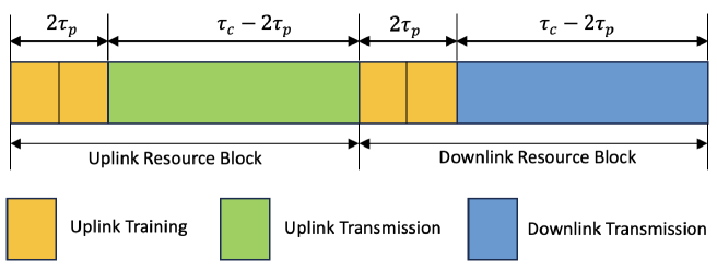
For channel estimation, users first send the pilots to APs which adopt the minimum mean square error (MMSE) estimate to acquire the uplink channel state information (CSI) [4]. Then, the obtained uplink CSI will be applied to introduce the other time instants’ channel distribution with the help of the temporal correlation coefficients across different time instants [15, 34]. The conventional MMSE estimation scheme simultaneously estimates the direct and RIS-assisted channels and might cause poor channel estimation accuracy [4, 21, 15]. As such, we build upon a novel two-phase channel estimation scheme to introduce extra estimation accuracy, as developed in [24]. As shown in Fig. 2, we divide the uplink channel estimation phase into two sub-phases requiring samples per sub-phase, and the two sub-phases estimate direct and RIS-assisted channels in sequence. This process is described next.
III-A Fractional Power Control-aided Pilot Assignment
III-A1 Fractional Power Control
In the uplink channel estimation phase, we utilize the user’s large-scale fading coefficients to introduce an appropriate fractional power control to counteract the near-far effects and improve the estimation accuracy[35, 36]. As such, the pilot power of the -th user can be obtained by
| (15) |
where represents the direct channel estimation and RIS-assisted channel estimation sub-phase, respectively. , with , the pilot power without power control.
III-A2 Pilot Assignment
To further guarantee a certain QoS for all users, we apply a large-scale fading coefficient-based pilot assignment applying the fractional power control to reduce the pilot contamination [25]. Firstly, for each sub-phase, the -th AP with the largest can be chosen as the prime AP of the -th user,
| (16) |
where denotes the ongoing sub-phase and subsequently, the -th AP determines the pilot sequence allocation of to the -th user during the relevant sub-phase. To mitigate pilot contamination, we have for , and for , we have
| (17) |
where represents the set of users assigned with pilot , and will be updated when every -th user () has been allocated with its own pilot sequence based on (17). With the help of the pilot assignment, we can determine (, ), as the set of users sharing the same pilot sequence including the -th user itself.
III-B Uplink Channel Estimation
We define as the pilot allocated to the -th user with , where is the pilot length. Usually, the coherence interval length is much larger than to guarantee the transmission efficiency, implying that [2, 6]. Different users will share the same pilot sequence in this case, leading to pilot contamination [37]. According to the pilot assignment procedure, is the set of users sharing the same pilot, including the -th user, in the ongoing sub-phase. Inevitably, .
III-B1 Direct channel estimation sub-phase
All RIS elements are OFF in the current sub-phase. Then, all users transmit their pilots to the APs to estimate the direct channel. pre-defined mutually orthogonal pilot sequences are used in this sub-phase. Thus, the pilot sequence is sent only at time instant within the sub-phase [11]. is the time instant index assigned to the -th user, and the other users in the pre-defined set share the same pilot transmission time instant, namely, . The pilot signal, , received at the -th AP at the -th time instant is formulated as
| (18) |
where is the pilot power of -th user. is the additive white Gaussian noise (AWGN) at the -th AP during this sub-phase with -th column satisfying , where is the noise power. We focus on the channel estimates at -th time instant in the following, where . Then, these estimates will be treated as the initial states to generate the other time instants’ channel estimates. We can obtain the effective channel at the -th time instant based on the channel at the -th time instant as
| (19) |
By projecting on , we can obtain
| (20) |
Given (20), the MMSE estimation of is given by
| (21) |
where
| (22) |
| (23) |
III-B2 RIS-assisted channel estimation sub-phase
All RIS elements are ON in this sub-phase. Similarly, the pre-defined pilot sequences are applied and the pilot sequence is sent only at time instant during the current sub-phase[11]. is the time instant index assigned to users utilizing the same time instant as the -th user, follows . As such, the received pilot signal at the -th AP can be expressed as
| (24) |
where is the AWGN matrix in this sub-phase with . Moreover, is the EMI of the -th RIS with -th column satisfying . Since the direct link has already been estimated in the first sub-phase and is known at the -th AP; then, we subtract from , which leads to
| (25) |
Similar to (19), we can obtain the effective channel at the -th time instant as
| (26) |
The projection of on equals to
| (27) |
Given (27), the MMSE of is defined as
| (28) |
where
| (29) |
| (30) |
Based on the above, the sum of the direct channel estimate and cascaded RIS-assisted channel estimates introduces the MMSE channel estimate , which can be formulated as
| (31) |
The channel estimate and the channel estimation error are distributed as and , respectively, with , .
IV Uplink Data Transmission
The uplink system performance with channel aging and EMI is studied in this section. We apply LSFD at the CPU and local MR at the APs during the uplink transmission [6, 11]. The closed-form SE expressions are derived with uplink fractional power control to evaluate the system performance.
IV-A Uplink Data Transmission
First, APs utilize their local channel estimates to estimate the uplink data locally. Then, these uplink data estimates will be sent to the CPU, which will complete the data detection[11, 38]. Thus, is the received signal at the -th AP within , formulated as
| (34) |
where is the user transmit power, is the uplink power control coefficient with . is the transmit signal from -th user, is the EMI of -th RIS. is the AWGN at the -th AP.
Then, the -th AP processes the multiplication of its received signal and the local channel estimate conjugate to detect the transmit signal from the -th user [6]. Next, the obtained is sent to the CPU to obtain by utilizing the weight vectors , with elements . is given by (35) at the top of this page. denotes the desired signal, and are the beamforming gain uncertainty and channel aging effect, is the inter-user interference, is the EMI term and is the noise term, respectively.
| (35) |
IV-B Performance Analysis
Inevitably, the desired signal can be degraded by the channel aging effect since decreases with the increasing time instant index . According to (35), the achievable uplink SE of the -th user based on the use-and-then-forget (UatF) bound [38, 11], can be lower-bounded as
| (36) |
where , the signal-to-interference-plus-noise ratio (SINR), is formulated as
| (37) |
where the sum of beamforming uncertainty and channel aging effect can be replaced by
| (38) |
Then, the closed-form expressions of uplink SE terms are given by
| (39) |
| (40) |
| (41) |
| (42) |
Proof: Please refer to Appendix A.
By utilizing the LSFD receiver cooperation from [38, 6], the SINR of the -th user can be maximized with the weight vector given by (43) at the top of the next page. This weight vector will vary for each time instant and will be optimized by the CPU.
| (43) |
IV-C Uplink Power Control
From (37), it is observed that the EMI affects the user performance differently because of the different user locations. To further reduce the impact of EMI, we apply fractional power control to eliminate the near-far effects [35]. Similar to the fractional power control introduced in (15), the uplink power control coefficient of the -th user is selected as
| (44) |
V Downlink Data Transmission
The proposed system’s downlink performance with channel aging and EMI is investigated in this section. Similar to uplink transmission, we derive novel downlink SE closed-from expressions and utilize downlink fractional power control for the system performance evaluation
V-A Downlink Data Transmission
The downlink data transmission from all APs to all users is composed of a broadcast channel making use of a precoding vector [16]. We treat the uplink channel transpose as the downlink channel based on the channel reciprocity characteristic of TDD operation.[17, 33]. As such, the transmit signal at time instant from the -th AP can be formulated as
| (45) |
where is the downlink transmit power at APs, is downlink power control coefficients selected to meet . is the signal sent to the -th user, same for all APs. In this work, we utilize conjugate beamforming, namely, for . According to (33), (46) describes the -th user’s received signal at the top of this page. is the EMI of the -th RIS, is the AWGN at the -th user at time instant .
| (46) |
V-B Performance Analysis
According to (46), the downlink achievable SE of the -th user is lower bounded by [4, 11]
| (47) |
where is the effective SINR at time instant following the similar calculation for (37). All downlink SE terms in (46) can be computed with the help of Appendix A, (48) shows the inter-user interference power summation at the top of the next page,
| (48) |
and the EMI power is given by
| (49) |
Then, (50) at the top of the next page shows the closed-form expression of .
| (50) |
V-C Downlink Power Control
VI Energy Efficiency
We investigate the total EE in this section using a realistic power consumption model [26]. RISs with passive elements do not cause power consumption.
VI-A Total Energy Efficiency
In general, the total EE (bit/Joule) equals the sum throughput (bit/s) divided by the total power consumption (Watts) of the proposed system[39, 16], and is expressed as
| (52) |
where and denote the total power consumption and the system bandwidth, respectively. Looking jointly at the uplink and downlink data transmissions, represents the sum SE over all users and can be given by[40, 11]
| (53) |
VI-B Power Consumption Model
Inspired by [26], we develop a power consumption model for the proposed system. First, the resource block contains time instants, and time instants are utilized for the uplink channel estimation. The rest time instants are assigned to uplink and downlink data transmissions. Then, the total power consumption with circuit consumption throughout the resource block is defined as [11, 41]
| (54) |
where , and are the respective power amplifier (PA) powers of channel estimation, uplink and downlink transmission (in Watts), including radiated transmit power and PA dissipation[11, 26]. Thus, these PA powers are given by
| (55) |
| (56) |
| (57) |
where , are the respective PA efficiency at -th user and -th AP. Moreover, the circuit power (CP) consumption is represented by,
| (58) |
where the fixed power consumption, , is composed of control signalling, site-cooling, and load-independent backhaul and baseband processor powers [26]. The transceiver chain power consumption is , the channel estimation process power consumption is , the power consumption of the channel coding and decoding is , the load-dependent backhaul power is , and the linear processing power is [42]. The power consumption terms can be modelled as:
VI-B1 Transceiver Chains
VI-B2 Channel Estimation
This process (once per resource block) is performed locally at the APs with computational efficiency (flops/Watt). Each AP receives the pilot signal to estimate each user’s channel via the pilot sequence multiplication during each channel estimation sub-phase [44]. Referring to [26], this process requires Watt. As such, the channel estimation process power consumption, , is given by
| (60) |
VI-B3 Coding and Decoding
APs apply channel coding and modulation to information sequences, and users decode their own sequences via the fixed-complexity algorithm in the downlink[26]. The uplink will perform the opposite. Then, is given by
| (61) |
where and are the respective coding power and decoding power (in Watt per bit/s).
VI-B4 Backhaul
The downlink/uplink data between the CPU and all APs are transferred via the backhaul. Moreover, the sum of load-dependent and load-independent powers can model the backhaul power consumption. contains the load-independent power. The load-dependent power , proportional to the sum throughput, can be computed as [11]
| (62) |
where (in Watts per bit/s) is the backhaul traffic-dependent power at -th AP.
VI-B5 Linear Processing
The transmit precoding and receiving combining at each AP are utilized to process the transmitted and received signals, respectively. This introduces
| (63) |
where is the power consumption to generate matrix-vector multiplications [26]. Then, denotes the power required to compute precoding and combining matrices once per resource block. Since we utilize conjugate beamforming, this is
| (64) |
VII Numerical Results
| Parameter | Value |
|---|---|
| Downlink fractional power control coefficient: | 0.5 |
| Computational efficiency at APs: | 12.8 Gflops/W |
| PA efficiency at APs: | 0.39 |
| PA efficiency at users: | 0.3 |
| Fixed power consumption: | 18 W |
| Power to run circuit components at APs: | 1W |
| Power to run circuit components at users: | 0.1 W |
| Power for coding of data signals: | 0.1 W/(Gbit/s) |
| Power for decoding of data signals: | 0.1 W/(Gbit/s) |
| Power for backhaul traffic: | 0.25 W/(Gbit/s) |
, , , .
index with , , , ,
, .
VII-A Channel Estimation and Resource Block Length
This work considers a simulation setup with APs, users and RISs located within a geographic area of km2, where km. Similar to [24], APs and users/RISs are randomly and independently distributed in two adjacent sub-regions with km, km and km. () models the large-scale fading coefficients. is the three-slope path loss and is log-normal shadowing with the standard deviation [1, eq.(52)-(53)]. This paper focuses on m, m, . The AP, RIS and user heights are 15 m, 30 m and 1.65 m [4]. The large-scaling fading coefficients are assumed to be constant since the distance variation is negligible compared with the initial distance. Moreover, the exponential correlation model in[45, 27] is utilized for the spatial correlation of APs. Until otherwise stated, all users experience the same velocity, , and LSFD receiver is selected for uplink transmission. In addition, the pilot sequence length for channel estimation is , the carrier frequency equals GHz, the bandwidth equals MHz, the time instant length equals ms. We also set downlink power as , pilot and uplink power as , dBm, and Table I displays the other power consumption parameters[16, 26]. We assume that all RIS elements with provide a fixed phase shift of and amplitude coefficient, unity [6, 2].
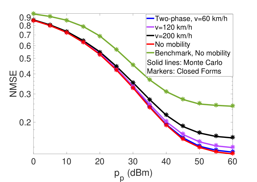
The NMSEs of the proposed system versus with different user velocities are shown in Fig. 5. The commonly-used MMSE scheme with equal power allocation is the benchmark estimation scheme[30, 6, 16]. The closed-form expressions generated by (7), (31)-(32) can closely match the analytical results. Note that introduces severe pilot contamination since it is much smaller than the number of users, and EMI also degrades the estimation accuracy. A non-zero error floor appears, and no-mobility scenarios still experience the non-zero error floor as increases. In addition, increasing mobility introduces a higher channel aging effect and degrades estimation inaccuracy. However, the proposed two-phase scheme can introduce additional estimation accuracy gain to lower the NMSE, and the results even outperform those of the benchmark scheme without user mobility.
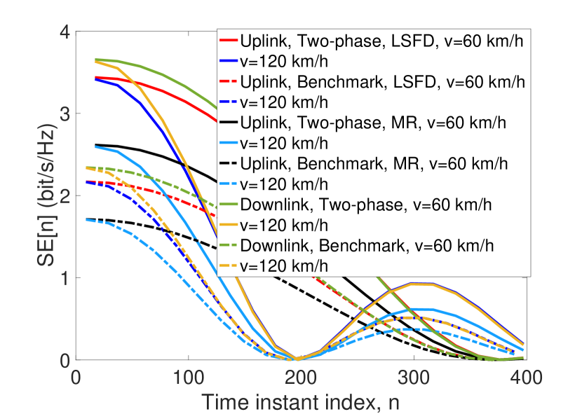
Fig. 5 shows the uplink (UL) and downlink (DL) , , at -th time instant regarding the first 400 time instant index, respectively. The data transmission time index for the proposed two-phase scheme starts at , and the benchmark scheme starts at . Although the two-phase scheme reduces the transmission efficiency compared to the benchmark scheme by , the two-phase scheme achieves better performance considering channel aging and EMI. It shows that decreases with user velocity at each time instant. Moreover, the first zero position will be shifted to the left side with higher user velocity, and the fluctuation peak becomes smaller with increasing time instant index. Therefore, selecting a reasonable resource block length is essential to mitigate the channel aging effect. In this case, we select no larger than the first zero index value and take the maximum user velocity into account. As such, in the following, we consider , and all users have the same velocity .

(except for the marked ones), , .
AP with , , , .
, , , .
RIS with , , , .
VII-B Spectral Efficiency and Energy Efficiency Analysis
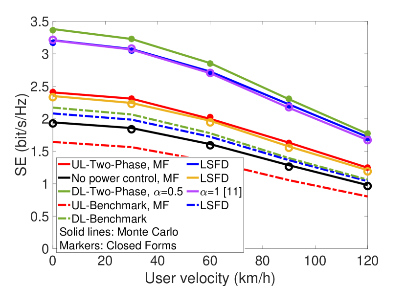
The achievable uplink SE in (36) with MF and LSFD and the downlink SE in (47) versus user velocity are shown in Fig. 5. The uplink closed-form expressions in (38)-(43), and downlink closed-form expressions in (50)-(49) can match the analytical results, respectively. It shows that increasing user velocity decreases the uplink and downlink SE. Moreover, the uplink SE with LSFD can achieve a larger -likely SE than that with MF. The uplink SE with fractional power control achieves a larger -likely SE than that without fractional power control, namely, . Similarly, the downlink power control in [11] with , achieves a smaller -likely SE than that of in our work. Moreover, the SE with the proposed two-phase scheme achieves a larger -likely SE than that of the benchmark scheme. Thus, the proposed RIS-assisted cell-free massive MIMO systems can improve the system performance of mobility scenarios.
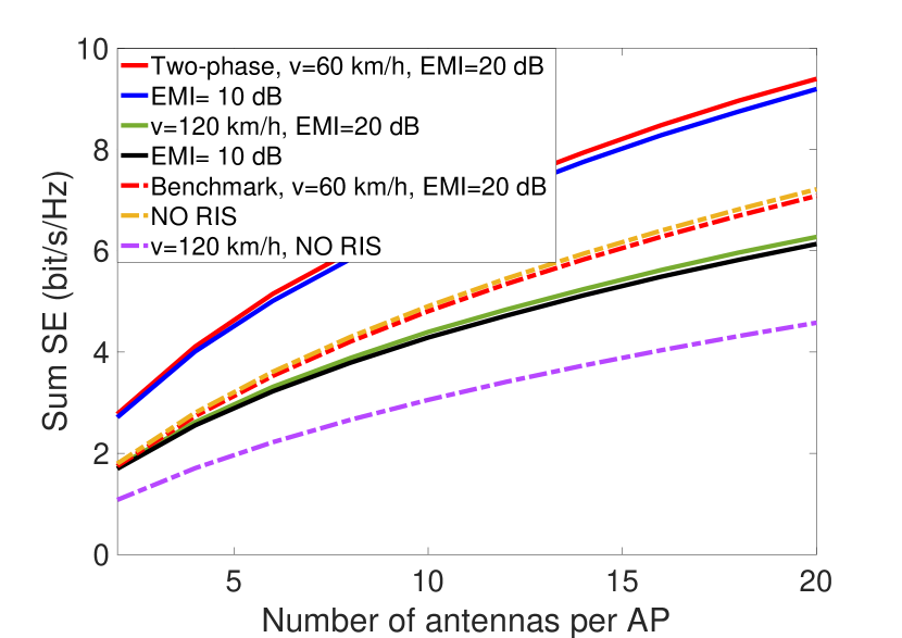
Fig. 8 shows the insight of the sum SE in (53) versus the number of APs, and Fig. 8 shows the insight of the sum SE versus the number of antennas per AP, evaluating different user velocities, users and EMI. In this work, the RIS-free cell-free massive MIMO system utilizes the benchmark estimation scheme. Increasing APs and antennas per AP can introduce increasing spatial degrees of freedom to facilitate more efficient beamforming; therefore, the sum SE can be improved. Applying more users can also benefit the system’s performance. Although EMI and channel aging introduce SE degradation, the proposed system increasingly outperforms RIS-free cell-free massive MIMO systems. Moreover, increasing APs can make compensation for the performance degradation caused by channel aging and EMI since increasing APs can achieve an SINR increase nearly proportional to it. Moreover, when is observed, the sum SE of can achieve a -likely SE than that of , while the sum SE of achieves a -likely SE than that of , which is a much smaller increase. It shows that the performance gains of increasing AP antennas will diminish with significantly large AP antennas.
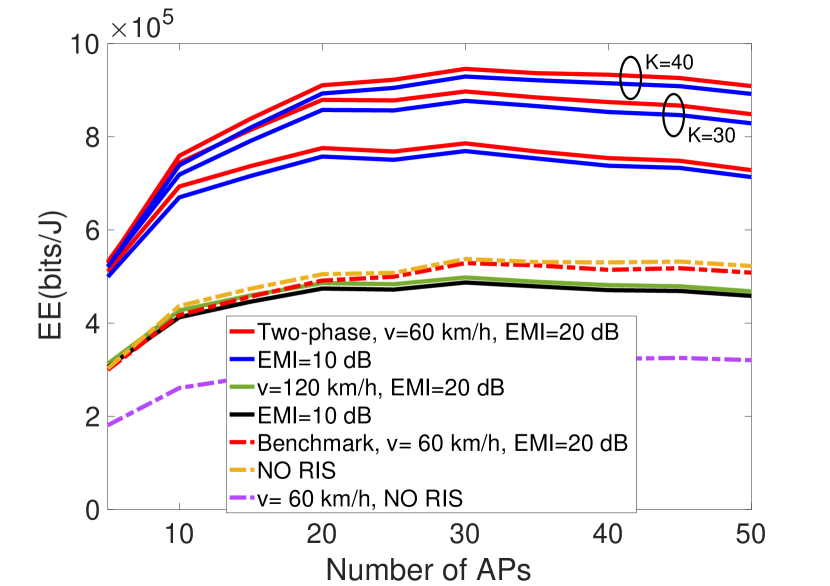
Fig. 8 displays the total EE in (52) versus the number of APs with various user velocities, users and EMI. We can find that the increasing APs can increase the total EE and then slowly decrease it. We can select as the optimal number of APs to achieve the EE maximization under given scenarios. This works because the sum SE increases as a logarithmic function of the number of APs, while the proposed power consumption model indicates that the power consumption increases as a nearly linear function of the number of APs. More users achieve a better EE, while the performance gain will diminish since more users introduce a large increase in power consumption than that of the SE and diminish the performance growth. Moreover, a larger user velocity results in a total EE reduction and introduces more APs to meet the required EE. Thus, increasing APs appropriately can compensate for the performance degradation introduced by channel aging and EMI on the total EE.
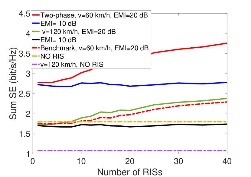
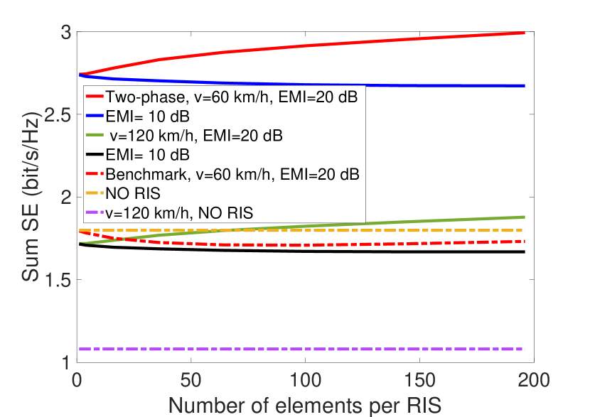
Fig. 11 and Fig. 11 show the sum SE versus the number of RISs and the number of elements per RIS, respectively. Increasing the number of RISs and elements per RIS is beneficial to neutralizing the performance degradation caused by channel aging and moderate EMI, i.e., . Moreover, when the number of RISs is , it shows that the sum SE experiences a fluctuation. However, when the severe EMI works with , the proposed system cannot meet performance improvement, even experience performance degradation since an increasing number of RISs and RIS elements will introduce extra EMI. This result suggests that with severe EMI, it is crucial to introduce EMI elimination schemes to release the benefits of introducing RISs. Even though severe EMI might degrade the performance, the proposed system can still outperform RIS-free cell-free systems.
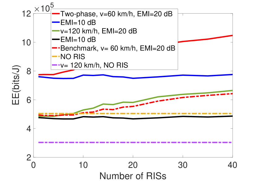
Fig. 11 illustrates the relationship between the number of RISs and the total EE in (52) with different user velocities and EMI. It shows that since all RIS elements are passive without power consumption, the increasing number of RISs will only increase the -based power consumption, which is not the determinate part of total power consumption when is moderate. As such, the total EE experiences almost the same trend as the sum SE with increasing RISs. Therefore, in RIS-assisted cell-free massive MIMO systems, increasing RISs can help to improve EE performance and reduce the channel aging effect when EMI is moderate. However, similar to sum SE, when EMI is severe, likely, , increasing the number of RISs cannot positively affect the total EE performance.
VIII Conclusion
This paper investigated the system performance of spatially correlated RIS-assisted cell-free massive MIMO systems with channel aging and EMI. We considered the uplink LSFD receiver and downlink conjugate beamforming. Uplink and downlink fractional power control are developed to improve system performance. By applying a two-phase channel estimation scheme, we derived closed-form channel estimation NMSE, uplink and downlink SE expressions to analyze the performance with channel aging and EMI. We also proposed a practical power consumption model to analyze the total EE. We find that increasing channel aging and moderate EMI causes performance degradation in both sum SE and total EE, and introducing more APs, AP antennas, RISs and RIS elements can improve the system performance. However, severe EMI could reduce the benefits of applying more RISs or RIS elements. As such, it might be challenging to deploy RISs in cell-free massive MIMO systems in high-EMI environments. Motivated by the results obtained, the EMI elimination scheme in the EMI-aware environment to release the benefits of applying RISs will be our focus of future work.
Appendix A Derivation of uplink SE approximations
This appendix provides the detailed derivation of by using the UatF bound [38, 11] to obtain the SE of -th user in (36). According to the MMSE properties, the estimate and estimation error are uncorrelated[16]. The users in the same set, , , share the same pilot sequence and is correlated with . We can obtain the following derivations in reference to [30, 6].
A-1 Compute
the desired signal is given by,
| (65) |
with .
A-2 Compute
The inter-user interference term can be first decomposed as
| (66) | ||||
We decompose (66) into two parts: and . First, by utilizing (33), the procedure of is shown as
| (67) |
The relevant terms can be further described as (68)-(71), where (68) is at the top of the next page,
| (68) |
| (73) |
Consequently, by plugging (68)-(71) into (67), and (73) into (72), we can transfer the inter-user interference (66) into (74) at the top of this page
| (74) |
with , where . The -th element in can be defined as . The diagonal elements are all zero, namely, . Furthermore, we define , with .
A-3 Compute
| (75) |
with , where
| (76) |
A-4 Compute
The noise term is computed by
| (77) |
with .
According to the above procedure, the proof is completed.
References
- [1] H. Q. Ngo et al., “Cell-free massive MIMO versus small cells,” IEEE Trans. Wireless Commun., vol. 16, no. 3, pp. 1834–1850, 2017.
- [2] T. Van Chien et al., “Reconfigurable intelligent surface-assisted cell-free massive MIMO systems over spatially-correlated channels,” IEEE Trans. Wireless Commun., vol. 21, no. 7, pp. 5106–5128, 2022.
- [3] H. He et al., “Cell-free massive MIMO for 6G wireless communication networks,” J. Commn. Net., vol. 6, no. 4, pp. 321–335, 2021.
- [4] Y. Zhang et al., “Performance analysis of RIS-assisted cell-free massive MIMO systems with transceiver hardware impairments,” IEEE Trans. Commun., pp. 1–1, 2023.
- [5] E. Björnson et al., “Deploying dense networks for maximal energy efficiency: Small cells meet massive MIMO,” IEEE J. Sel. Areas Commun., vol. 34, no. 4, pp. 832–847, 2016.
- [6] E. Shi et al., “Uplink performance of RIS-aided cell-free massive MIMO system with electromagnetic interference,” IEEE J. Sel. Areas Commun., vol. 41, no. 8, pp. 2431–2445, 2023.
- [7] ——, “Spatially correlated reconfigurable intelligent surfaces-aided cell-free massive MIMO systems,” IEEE Trans. Veh. Technol., vol. 71, no. 8, pp. 9073–9077, 2022.
- [8] J. Qian et al., “The effect of spatial correlation and mutual coupling on cell-free massive MIMO,” Proc. IEEE WCNC, accepted, 2024.
- [9] E. Nayebi et al., “Precoding and power optimization in cell-free massive MIMO systems,” IEEE Trans. Wireless Commun., vol. 16, no. 7, pp. 4445–4459, 2017.
- [10] G. Interdonato et al., “Enhanced normalized conjugate beamforming for cell-free massive MIMO,” IEEE Trans. Commun., vol. 69, no. 5, pp. 2863–2877, 2021.
- [11] J. Zheng et al., “Impact of channel aging on cell-free massive MIMO over spatially correlated channels,” IEEE Trans. Wireless Commun., vol. 20, no. 10, pp. 6451–6466, 2021.
- [12] E. Björnson and L. Sanguinetti, “Scalable cell-free massive MIMO systems,” IEEE Trans. Commun., vol. 68, no. 7, pp. 4247–4261, 2020.
- [13] H. D. Tuan et al., “Scalable user rate and energy-efficiency optimization in cell-free massive MIMO,” IEEE Trans. Commun., vol. 70, no. 9, pp. 6050–6065, 2022.
- [14] Q. Wu et al., “Intelligent reflecting surface-aided wireless communications: A tutorial,” IEEE Trans. Commun., vol. 69, no. 5, pp. 3313–3351, 2021.
- [15] Y. Zhang et al., “Channel aging-aware precoding for RIS-aided multi-user communications,” IEEE Trans. Veh. Technol., vol. 72, no. 2, pp. 1997–2008, 2023.
- [16] A. Papazafeiropoulos et al., “Impact of channel aging on reconfigurable intelligent surface aided massive MIMO systems with statistical CSI,” IEEE Trans. Veh. Technol., vol. 72, no. 1, pp. 689–703, 2023.
- [17] Y. Zhang et al., “Performance analysis of reconfigurable intelligent surface assisted systems under channel aging,” Intelligent and Converged Networks, vol. 3, no. 1, pp. 74–85, 2022.
- [18] A. de Jesus Torres et al., “Electromagnetic interference in RIS-aided communications,” IEEE Wireless Commun. Lett., vol. 11, no. 4, pp. 668–672, 2022.
- [19] G. S. Chandra et al., “Downlink URLLC system over spatially correlated RIS channels and electromagnetic interference,” IEEE Wirel. Commun. Lett., vol. 11, no. 9, pp. 1950–1954, 2022.
- [20] S. Hassouna et al., “Reconfigurable intelligent surfaces aided wireless communications with electromagnetic interference,” in Proc. IEEE EuCAP, 2023, pp. 1–5.
- [21] M. a. Bashar, “On the performance of reconfigurable intelligent surface-aided cell-free massive MIMO uplink,” in Proc. IEEE GLOBECOM, 2020, pp. 1–6.
- [22] N. T. Nguyen et al., “Downlink throughput of cell-free massive MIMO systems assisted by hybrid relay-reflecting intelligent surfaces,” in Proc. IEEE ICC, 2022, pp. 1475–1480.
- [23] E. Shi et al., “Uplink performance of RIS-aided cell-free massive MIMO system over spatially correlated channels,” in Proc. IEEE GLOBECOM, 2022, pp. 3259–3264.
- [24] J. Qian et al., “Two-phase channel estimation scheme for RIS-assisted cell-free massive MIMO systems with electromagnetic interference,” Proc. IEEE MeditCom, Accepted, 2024.
- [25] X. Ma et al., “Active STAR-RIS aided cell-free massive MIMO: A performance study,” IEEE Trans. Veh. Technol., pp. 1–6, 2023.
- [26] E. Björnson et al., “Optimal design of energy-efficient multi-user MIMO systems: Is massive MIMO the answer?” IEEE Trans. Wireless Commun., vol. 14, no. 6, pp. 3059–3075, 2015.
- [27] X. Li et al., “Massive MIMO with multi-antenna users: When are additional user antennas beneficial?” in Proc. IEEE ICT, 2016, pp. 1–6.
- [28] Ö. T. Demir and E. Björnson, “Ris-assisted massive MIMO with multi-specular spatially correlated fading,” in Proc. IEEE GLOBECOM, 2021, pp. 1–6.
- [29] E. Björnson and L. Sanguinetti, “Rayleigh fading modeling and channel hardening for reconfigurable intelligent surfaces,” IEEE Wirel. Commun. Lett., vol. 10, no. 4, pp. 830–834, 2021.
- [30] E. Shi et al., “RIS-aided cell-free massive MIMO systems with channel aging,” IEEE Trans. Veh. Tech., pp. 1–16, 2024.
- [31] R. Chopra et al., “Uplink performance analysis of cell-free mMIMO systems under channel aging,” IEEE Commun. Lett., vol. 25, no. 7, pp. 2206–2210, 2021.
- [32] A. K. Papazafeiropoulos and T. Ratnarajah, “Deterministic equivalent performance analysis of time-varying massive MIMO systems,” IEEE Trans. Wireless Commun., vol. 14, no. 10, pp. 5795–5809, 2015.
- [33] J. Qian et al., “Partial CSI acquisition for size-constrained massive MIMO systems with user mobility,” IEEE Trans. Veh. Technol., vol. 67, no. 9, pp. 9016–9020, 2018.
- [34] A. K. Papazafeiropoulos, “Impact of general channel aging conditions on the downlink performance of massive MIMO,” IEEE Trans. Veh. Technol., vol. 66, no. 2, pp. 1428–1442, 2017.
- [35] R. Nikbakht et al., “Uplink fractional power control and downlink power allocation for cell-free networks,” IEEE Wirel. Commun. Lett., vol. 9, no. 6, pp. 774–777, 2020.
- [36] J. Zheng et al., “Cell-free massive MIMO with channel aging and pilot contamination,” in Proc. IEEE GLOBECOM, 2020, pp. 1–6.
- [37] J. Jose et al., “Pilot contamination and precoding in multi-cell TDD systems,” IEEE Trans. Wireless Commun., vol. 10, no. 8, pp. 2640–2651, 2011.
- [38] E. Björnson and L. Sanguinetti, “Making cell-free massive MIMO competitive with MMSE processing and centralized implementation,” IEEE Trans. Wireless Commun., vol. 19, no. 1, pp. 77–90, 2020.
- [39] J. Qian et al., “Multi-pair two-way massive MIMO relaying with zero forcing: Energy efficiency and power scaling laws,” IEEE Trans. Commun., vol. 68, no. 3, pp. 1417–1431, 2020.
- [40] E. Björnson et al., “Massive MIMO for maximal spectral efficiency: How many users and pilots should be allocated?” IEEE Trans. Wireless Commun., vol. 15, no. 2, pp. 1293–1308, 2016.
- [41] H. Q. Ngo et al., “On the total energy efficiency of cell-free massive MIMO,” IEEE Trans. Green Commun. Netw., vol. 2, no. 1, pp. 25–39, 2018.
- [42] G. A. Ubiali and T. Abrão, “XL-MIMO energy-efficient antenna selection under non-stationary channels,” 2020.
- [43] S. Cui et al., “Energy-efficiency of MIMO and cooperative MIMO techniques in sensor networks,” IEEE J. Sel. Areas Commun., vol. 22, no. 6, pp. 1089–1098, 2004.
- [44] J. Hoydis et al., “Massive MIMO in the UL/DL of cellular networks: How many antennas do we need?” IEEE J. Sel. Areas Commun., vol. 31, no. 2, pp. 160–171, 2013.
- [45] S. Loyka, “Channel capacity of MIMO architecture using the exponential correlation matrix,” IEEE Commun. Lett., vol. 5, no. 9, pp. 369–371, 2001.