Field-free Josephson diode effect in a -wave superconductor heterostructure
Abstract
We study superconductor/normal region/superconductor (SNS) Josephson junction formed using superconductors with , , and superconducting pairings. We show that the quality factor of the Josephson diode effect and its sign can be substantially tuned by the external magnetic field, gate voltage, and the length of the junction for all three types of pairings. We also identify the conditions under which the anomalous Josephson and Josephson diode effects can appear in the junction by analyzing appropriate symmetries. In particular, by breaking a -rotation symmetry, we show how a large field-free Josephson diode effect can be realized even in the absence of spin-orbit coupling. We also study the role of edge states appearing in the case of chiral superconductor with pairing. Our results demonstrate that the Josephson diode effect in a planar geometry can be used as a signature of unconventional superconducting pairings.
pacs:
Valid PACS appear hereI Introduction
The superconducting diode (SDE) and Josephson diode effects (JDE) have attracted considerable attention in recent years due to many potential applications in superconducting devices and quantum computing [1, 2, 3, 4, 5, 6, 7, 8, 9, 10, 11, 12, 13, 14, 15]. The effects are characterized by non-reciprocal behavior in the critical current, in particular, the current can be dissipationless in one direction and dissipative in the opposite direction. In the absence of both time-reversal and inversion symmetry, Josephson junctions (JJ) can exhibit the JDE, characterized by non-reciprocal behavior in the critical supercurrent () [16, 17, 18, 19, 20, 21, 22, 23, 24, 25, 26]. This means that the critical supercurrent in the “” direction () differs from that in the opposite “” direction (). This nonreciprocity in supercurrents holds promise for applications in superconducting electronics [27, 28].
The -wave superconductivity is very common and appears in cuprate superconductors. The bulk of traditional -wave superconductors is gapless. Recently, chiral -wave superconductivity has been proposed in magic angle bilayer twisted graphene [29, 30], in Bi/Ni bilayers [31], and in Sn/Si(111) [31]. It has been predicted that twisted bilayer cuprates can realize or pairings without gapless states in the bulk [32, 33]; however, further research is necessary to confirm these predictions [34, 35]. With the pairing, the bulk states are gapped, and instead, chiral edge states appear. Proximity induced superconductivity has been suggested in two-dimensional electron gas (2DEG) materials such as Bi2O2Se proximized with cuprates [36]. Furthermore, it has been demonstrated that a twisted bilayer cuprate exhibits time-reversal symmetry (TRS) breaking and JDE at specific twist angles [37, 38, 34].
In this work, we study superconductor/normal region/superconductor (SNS) Josephson junction formed with -wave superconductors. We consider , , and superconducting pairings that have been suggested in exfoliated layers of cuprate superconductors. We find that for the case of -wave pairing, the finite JDE can only occur in the presence of spin-orbit coupling (SOC) and magnetic field. The and pairings break TRS. As a result, in the presence of additional asymmetry (see Fig. 1) the TRS breaking results in JDE even in the absence of SOC and magnetic field. According to our results for pairing, the chiral edge modes show a clear contribution to JDE, which suggests that interference effects can be used to control JDE. We further confirm this by studying the distribution of the Josephson current in the junction and by identifying the Andreev bound states (ABS) from the local density of states (LDOS). Our proposal realizes a large, field-free JDE and demonstrates that JDE in a planar geometry can be used as a signature of unconventional superconducting pairings.
II Model and methods
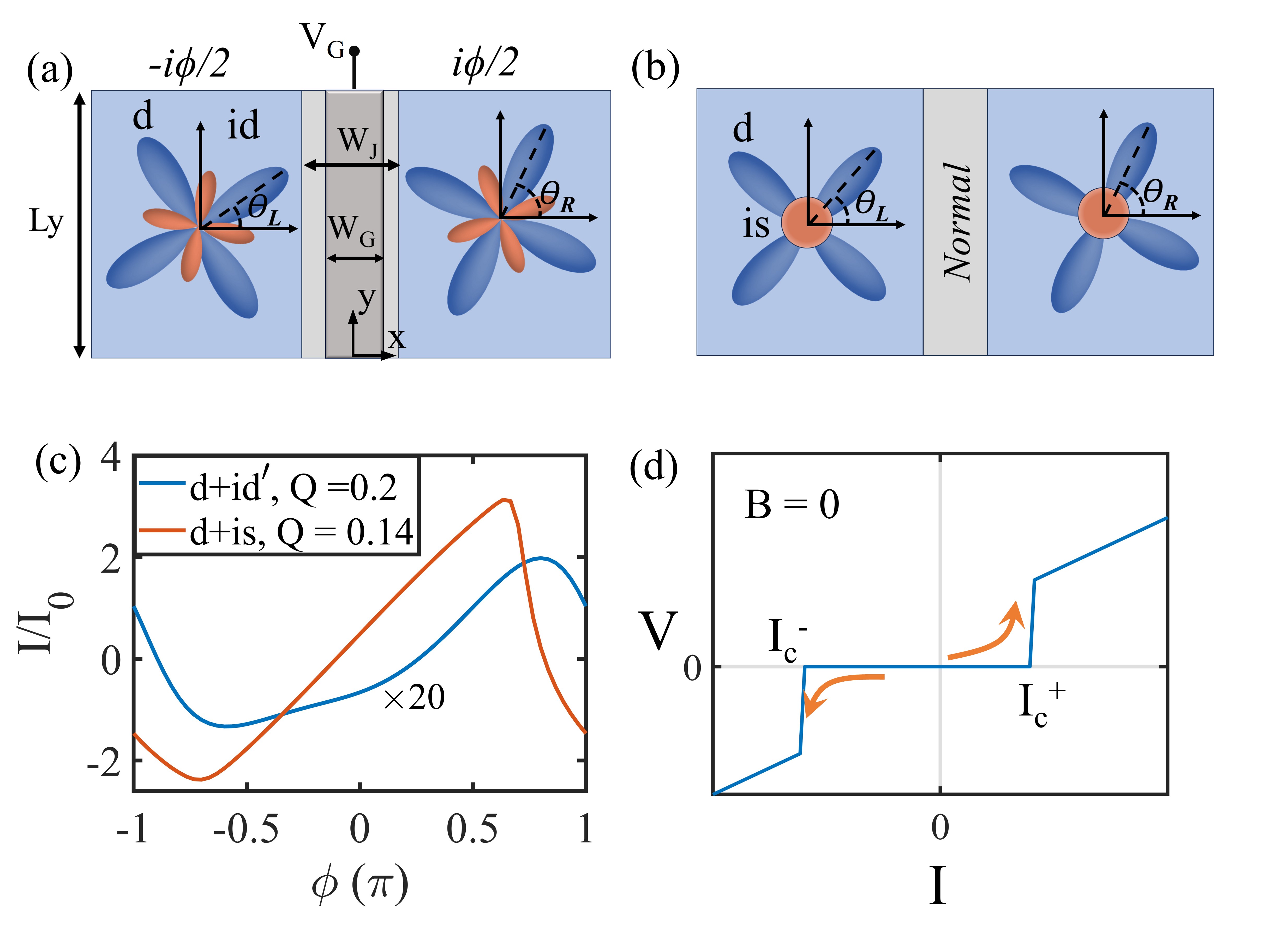
We consider SNS Josephson junction (JJ) formed using 2DEG with induced -wave, , or pairing, see Fig. 1. An electrical gate is applied to the normal region as shown in Fig. 1, which allows for the tunability of JJ.
The Bogoliubov–de Gennes (BdG) Hamiltonian of the system, written in the Nambu basis () in the continuous limit reads [39]
| (1) |
Here, is the effective electron mass, is the chemical potential, is the Rashba spin-orbit coupling strength, and describes the Zeeman energy, e.g., for an external magnetic field. The gate voltage is defined as . The pair potential is parametrized for pairing as
| (2) |
and for pairing as
| (3) |
where describes the angle between the -axis and the lobe direction of the pair potential. We denote () for the left (right) superconductor. The terms are only nonzero in the regions covered by superconductors where , . For the region covered by the left superconductor, we take , and for the region covered by the right superconductor, we take . We discretize the Hamiltonian (1) and use the tight binding approach where is the nearest neighbor hopping and is the lattice spacing. We use dimensionless units measuring energy in units of and length in units of . The SC coherence length is defined as . Typical material parameters we use in numerical calculations are as follows: , , , , and [40].
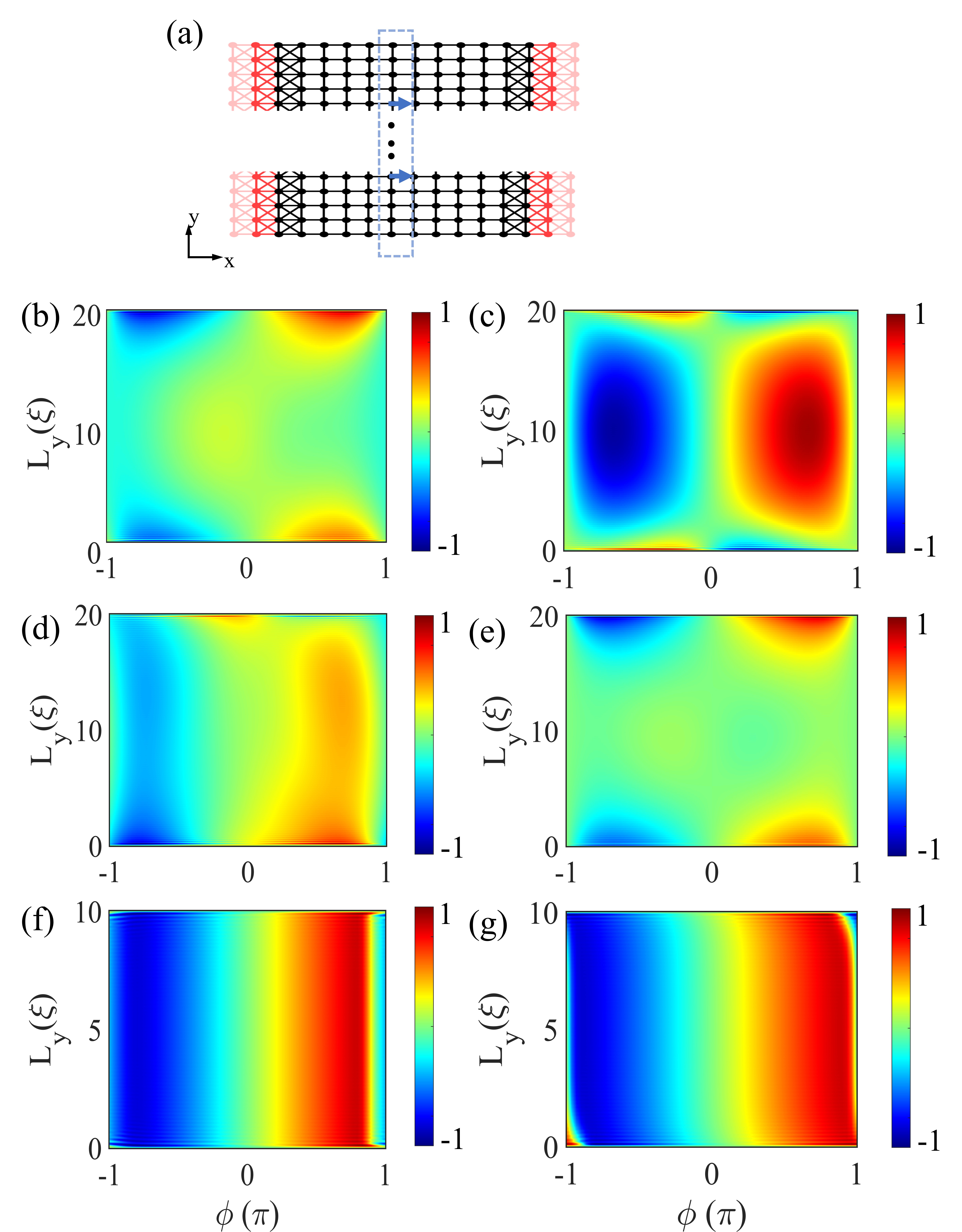
We calculate the conserved current inside the junction (see Fig. 8(a)) which does not require the self-consistent calculation. The self-consistent procedure would be required inside superconductor to ensure the current conservation. To calculate the equilibrium Josephson current, we use the Matsubara Green’s function obtained using the analytical continuation of the retarded Green’s function. The local current between the sites and can be expressed using the standard approach [41, 42, 43, 44, 45, 46]:
| (4) |
where is the Green’s function and is the Hamiltonian submatrix calculated between the sites and , with the lattice sites taken inside the normal region. The summation is performed over the fermionic Matsubara frequencies and the Green’s functions also accounts for the self energy of the leads. The total current is obtained by summing all contributions along the cut in -direction, , where is the unit vector along the -axis (see Fig. 8(a)). The diode effect is then characterized by the quality factor , where and are the critical current calculated by finding the maximum and minimum of current over . As an example, in Fig. 1(c) we show the current-phase relation (CPR) for and pairings. The figure shows the nonvanishing anomalous Josephson effect at provided that the two pairing lobes are rotated with respect to each other. Furthermore, CPR in the figure results in the quality factor equal to for pairing and for pairing.
We also calculate the local density of states (LDOS) using the expression:
| (5) |
where is the band broadening. The location of LDOS peaks allows us to determine energies of the Andreev bound states (ABS).
| SC Pairing | Symmetries to break or | |||
|---|---|---|---|---|
| terms to add for JDE | ||||
| + Rashba SOC | ||||
| + Rashba SOC | ||||
| + Rashba SOC | ||||
III Symmetry analysis
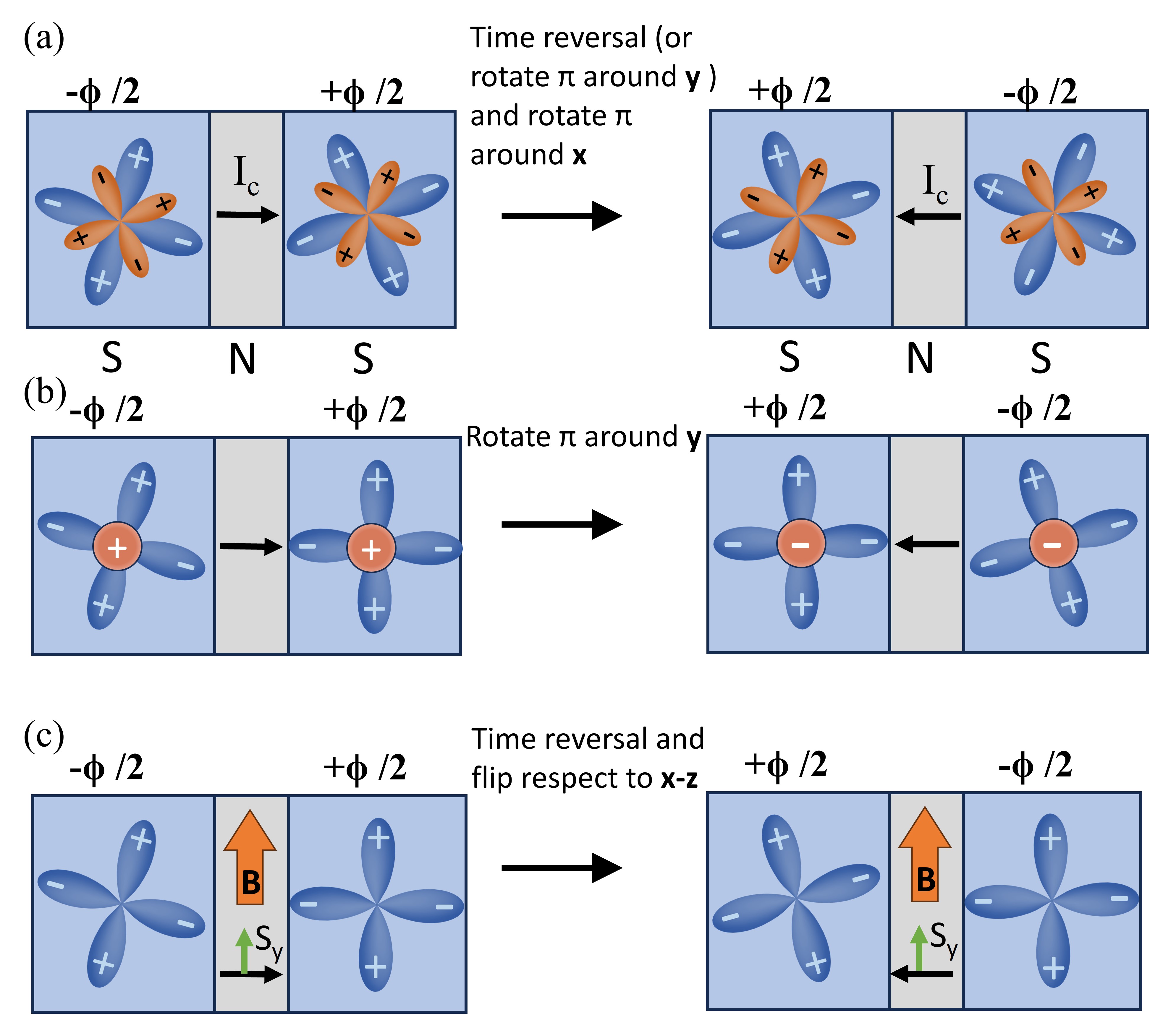
To understand how the anomalous Josephson effect and JDE can be achieved, we begin with a symmetry analysis of the system, followed by numerical simulations of the diode effect while varying various parameters. In order to get a non-reciprocal transport in a Josephson junction, it is required to have . If however there is a symmetry that reverses and then the anomalous Josephson effect and JDE (by extension of the above argument to applied voltage ) vanish. To identify such a symmetry, we start with analysis of systems with -wave pairings. In Table 1, we list whether TRS and -rotation symmetries with respect to and axis () are satisfied for the system in Fig. 1 for simple alignment of the pairing lobes. In the last column, we list modifications that are necessary to break the symmetry or symmetries prohibiting the anomalous Josephson effect. For example, in case of pairing, TRS is present, and . This means that to achieve the nonreciprocity, we need to break both TRS and spin rotational symmetry. The choice of the direction of the magnetic field and the presence of Rashba SOC guarantee that we cannot use and symmetries for the transformation that reverses both and . With pairing, all of the three symmetries (, , ) are separately broken. However, the combined symmetries and still need to be broken for the presence of the anomalous Josephson effect. This can be achieved by using JJ with an asymmetry (e.g. induced by gating) or by rotating the pairing lobes of the left and right superconductors with respect to each other. Finally, for the pairing, the rotational symmetries are present. Since reverses both and it has to be broken for the presence of the anomalous Josephson effect. As before, this can be achieved by using JJ with an asymmetry (e.g. induced by gating) or by rotating the pairing lobes of the left and right superconductors with respect to each other. The latter approach is explored in details in our numerical simulations. Figure 2 shows the pictorial demonstration of the symmetry analysis. In particular, Fig. 2(a) shows that for pairing the orientations of the pairing lobes in the left and right SCs (i.e. ) can break and symmetries. In Fig. 2(b), we show that for pairing, the orientations of the pairing lobes (i.e. ) break symmetry provided that . In Fig. 2(c), we assume pairing. Here, a Zeeman field along the axis is necessary to break TRS. To further break the spin rotation symmetries, the Rashba SOC term has to be added. It is worth mentioning that the anomalous Josephson effect has been predicted for -wave pairing without the presence of SOC by introducing appropriate magnetic textures [47].
IV Leads with -wave pairing
Here, we consider a ballistic JJ with superconducting leads featuring the pure -wave pairing. To treat systems with large , we assume here periodic boundaries along the axis and numerically find solutions characterized by the transverse wave vector . As a result, we solve numerically the effective one-dimensional scattering problem along the direction of the junction, afterwards summing the contributions from each . With this approach, we are able to reproduce analytical results in Ref. [48] where the Zeeman and Rashba terms were only present in the junction region.
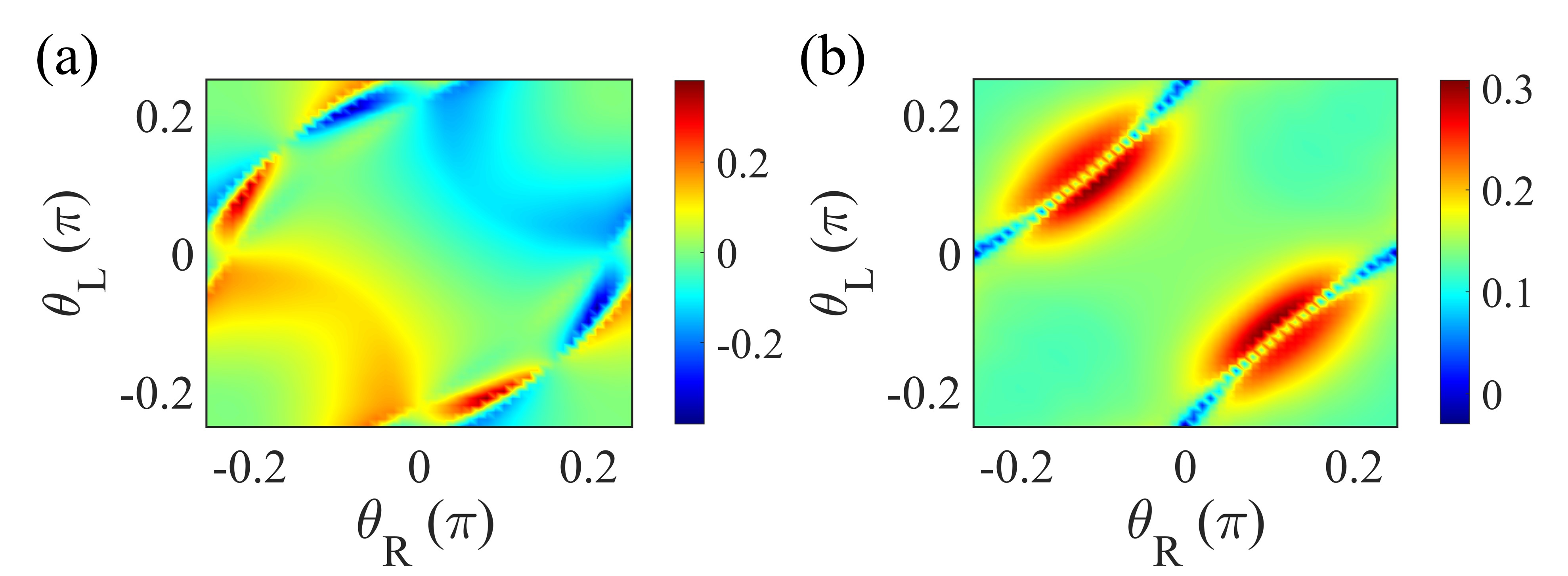
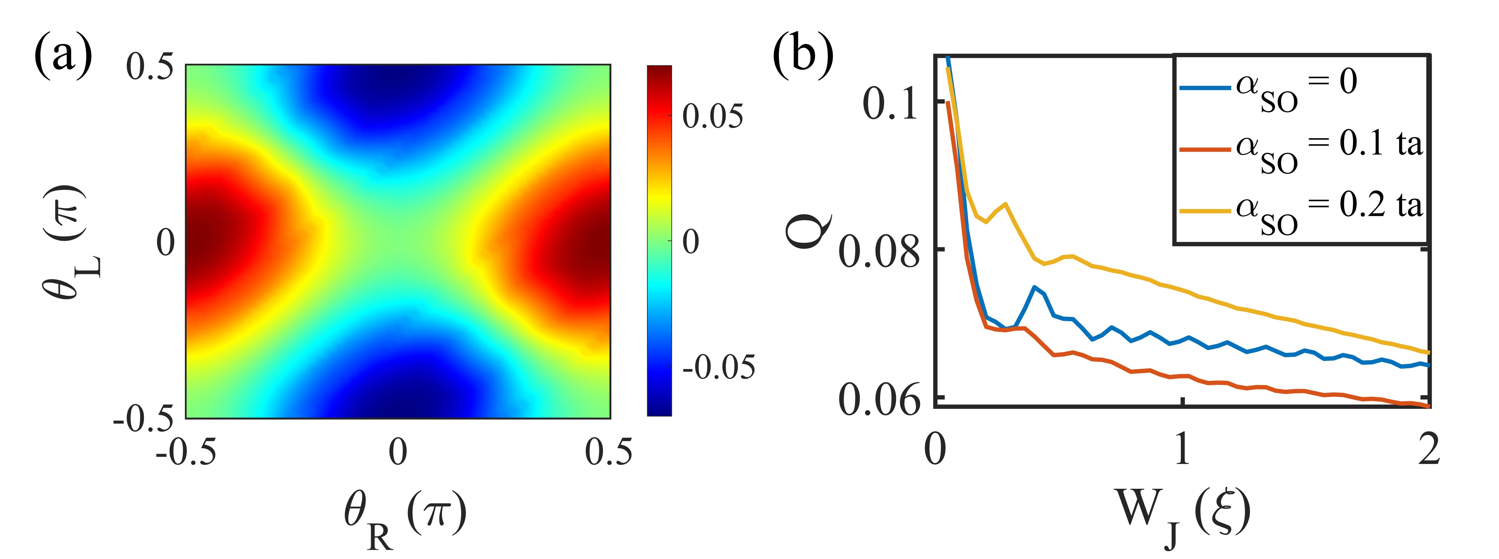
For an arbitrary orientation of the pairing lobes, the pairing potential can take a general form of . For nonvanishing JDE, as shown before, we need the Zeeman term to break the time-reversal symmetry, and the Rashba SOC to break the spin rotation symmetry. Figure 3 shows the quality factor plotted as a function of the pairing lobe orientation angles and . Variations in the lobe orientation can be achieved by adjusting the crystal orientation of SC leads. In Fig. 3(a), the Zeeman field is applied in the direction. The figure shows regions of large throughout the phase space. In Fig. 3(b), the Zeeman field is applied in the direction. For this direction of the Zeeman field, even with no rotation of lobes, i.e., for and , we observe large values of . Finally, we observe relatively weak JDE for the Zeeman field along the axis (not shown in the figure) in contrast to a JJ based on the topological insulator [9].
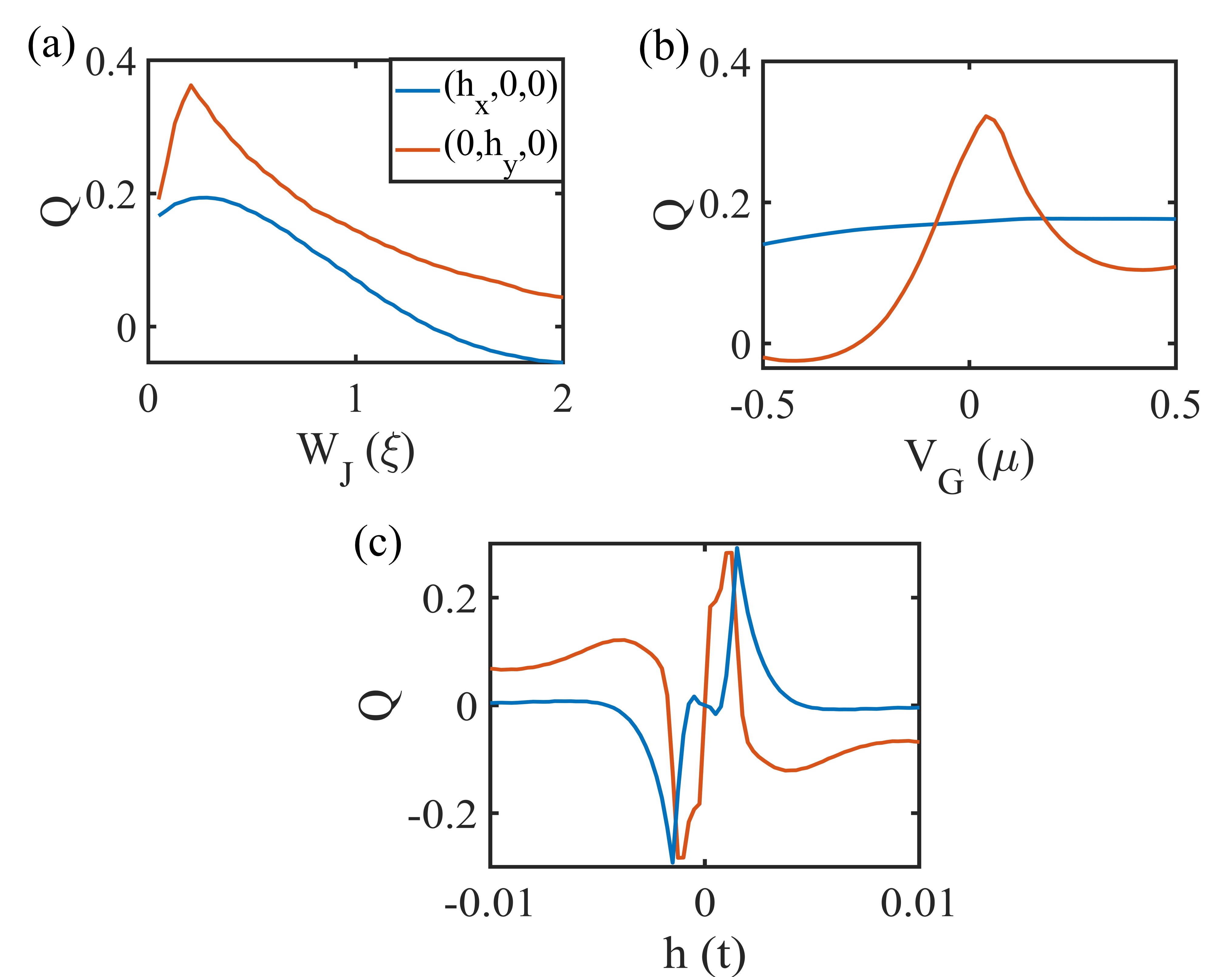
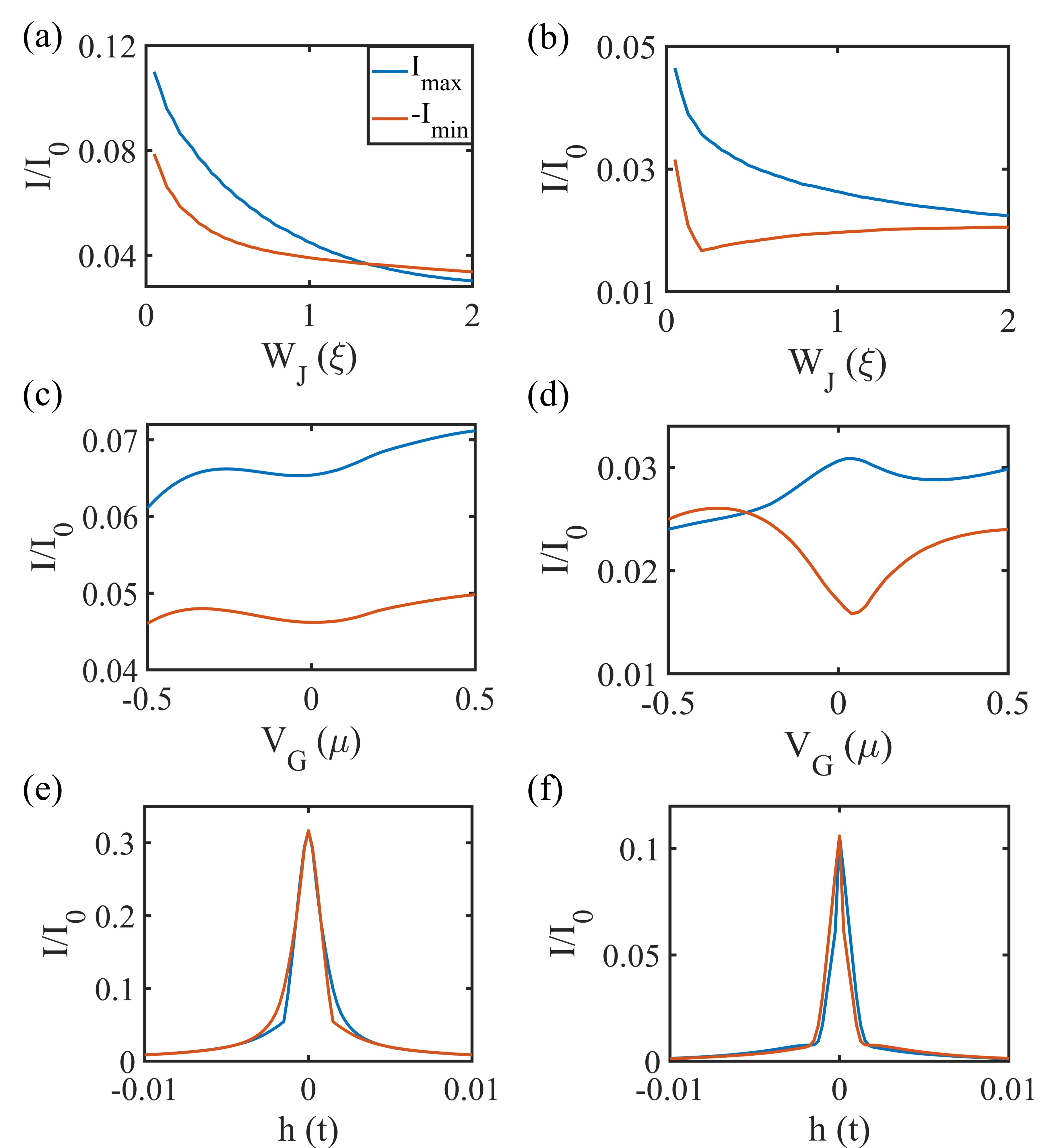
Several parameters can be adjusted to fine-tune the quality factor of JJ. Fist, we vary the junction width . As shown in Fig. 4(a), the quality factor shows the large variation and even sign change as is increased. This behavior stems from contributions of the higher order harmonics to the current-phase relation (CPR). Next, we also explore how depends on the gate voltage and the Zeeman field . Figure 4(b) demonstrates that can be effectively tuned by the gate voltage within the junction region for the Zeeman field along the axis. The variation of as a function of the Zeeman field along the and directions is shown in Fig. 4(c). In Fig. 4(c), we observe large variations as the Zeeman field is increased, with eventual suppression of JDE at large Zeeman fields. Even though the dependence of the quality factor on various parameters is complicated, some trends can be identified. This can be useful in fine tuning the diode effect for applications such as Josephson transistor.
This is further elucidated in Fig. 5 showing the evolution of the maximum, , and minimum, , Josephson currents. Figure 5 shows the evolution of and for the calculations in Fig. 4, for the Zeeman field along the axis in (a), (c), and (e) plots, and for the Zeeman field along the axis in (b), (d), and (f) plots. The high tunability of Josephson current is seen in Fig. 5(b) where a dip in corresponds to the peak observed in . In comparison, Fig. 5(a) shows a monotonic decay in both and corresponding to the smoother change in , as can be seen in Fig. 4(a). In the long junction limit , we observe that tends to zero. By looking at the variation of and as the gate voltage is varied in Fig. 5(c), we observe only minor change. However, Fig. 5(d) demonstrates high tunability by gate voltage as we observe a dip in and a peak in at around . In this case, the gating also substantially modifies , even leading to a sign change. Figures 5(e) and (f) show large and at small . Away from the region the magnetic field suppresses the supercurrent. We observe that the Zeeman field skews and in the opposite directions, which correspond to the sign change of seen in Fig. 4(c). Overall, Figs. 4 and 5 demonstrate high tunability of JDE for leads with the -wave pairing.
V Leads with pairing
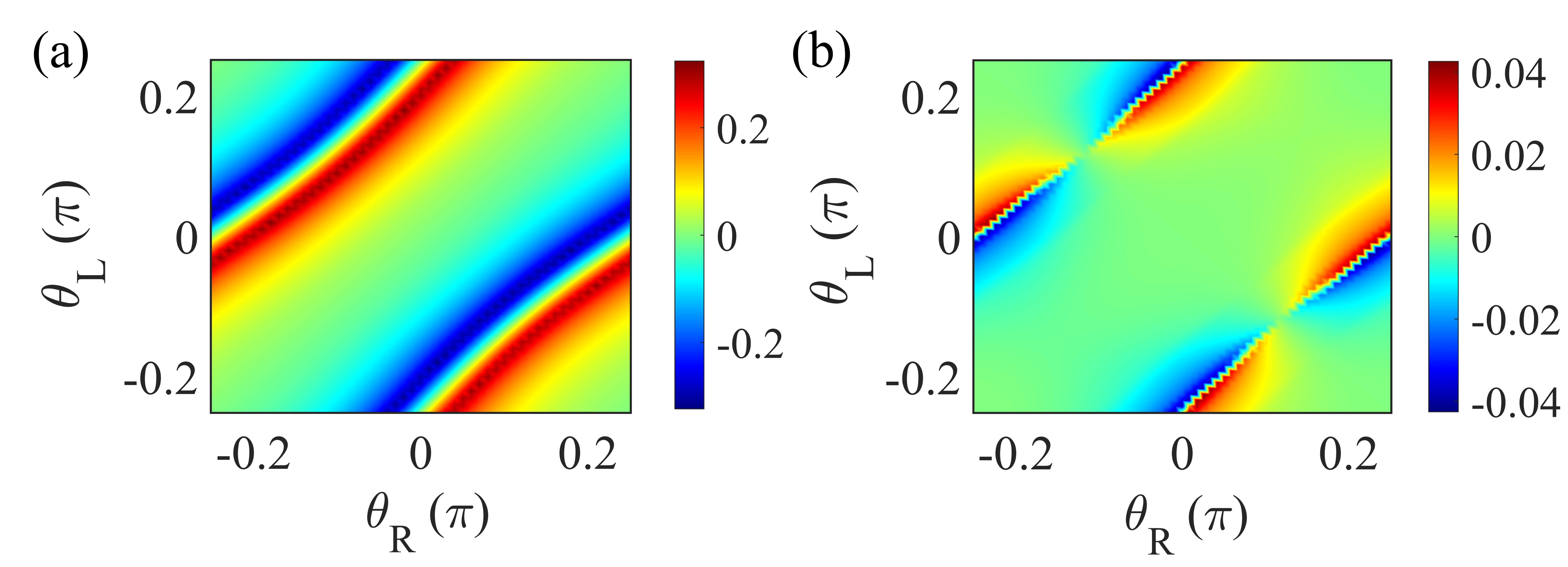
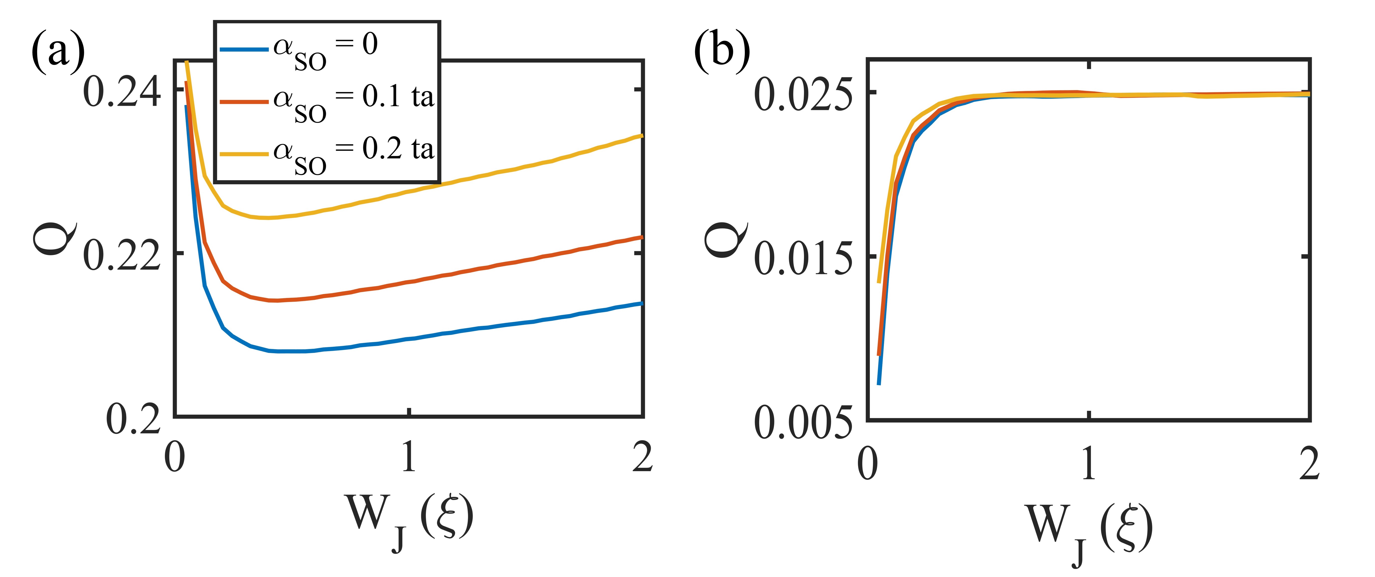
Now we consider a ballistic JJ with superconducting leads featuring the pairing. For this pairing, the TRS is broken. To satisfy the conditions of JDE, we still need to break rotational symmetries (see Table 1). This can be achieved by rotating the pairing lobes parametrized by angle in Eq. (II). Figure 6(a) shows the quality factor as a function of and without any Zeeman field or SOC for a N JJ. We observe a possibility of large JDE even in the absence of the Zeeman field and SOC. As the system may have the Rashba SOC, we also repeated the calculations with the inclusion of Rashba SOC, finding only minor differences. Figure 6(b) shows the quality factor as a function of and without any Zeeman field or SOC for a N JJ. Compared to the previous case, we observe significantly smaller values of . For this case no JDE is present on the off diagonal, i.e., . We further look at how Q evolves as is varied. Figure 7(a) shows for the case of a N JJ. The short junction limit shows the largest , although the decrease in as is increased is not significant. Figure 7(b) is the calculations for a N JJ. As before, we observe much smaller for superconductors with opposite chiralities.
In the case of pairing, the superconductors exhibit chiral edge states, with the relative sign of the and components determining the chirality of the system. To investigate how edge currents contribute to JDE, we examine the current distribution along the transverse direction for a JJ of finite width . Figure 8(a) illustrates the schematics of the current distribution calculation. We consider a N JJ in Figs. 8(b) and (c). We observe a concentration of Josephson current at the top and bottom edges, consistent with the effect of edge states. As expected, in Fig. 8(c) we observe vanishing JDE. In Fig. 8(b), the current in the bulk of the channel exhibits a significantly stronger anomalous Josephson effect compared to edges, and the edge part of the current mostly follows a CPR behavior resulting in relatively weak contribution to JDE. Figures 8(d) and (e) show the current distribution for a N JJ. In Fig. 8(e), we observe vanishing JDE. In Fig. 8(d), both the bulk and the edge modes seem to contribute to JDE; however, overall JDE is much weaker in this case. If we compare the current distribution calculations for in Figs. 8(b–e) with similar calculations for case in Figs. 8(f, g), we observe a clear difference that can be associated with the edge states present in systems. Figures 8(f, g) will be discussed in more detail in the next section.
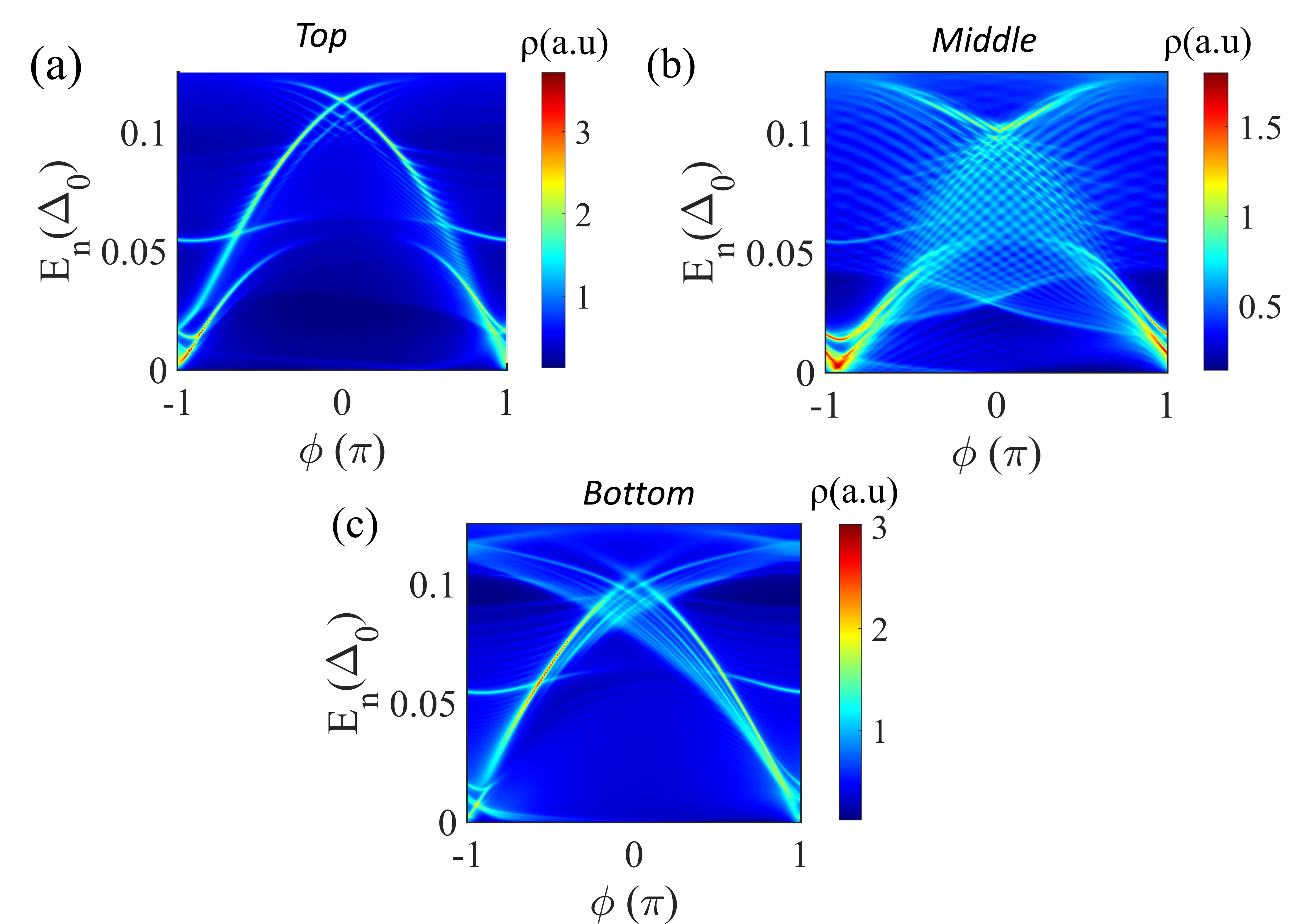
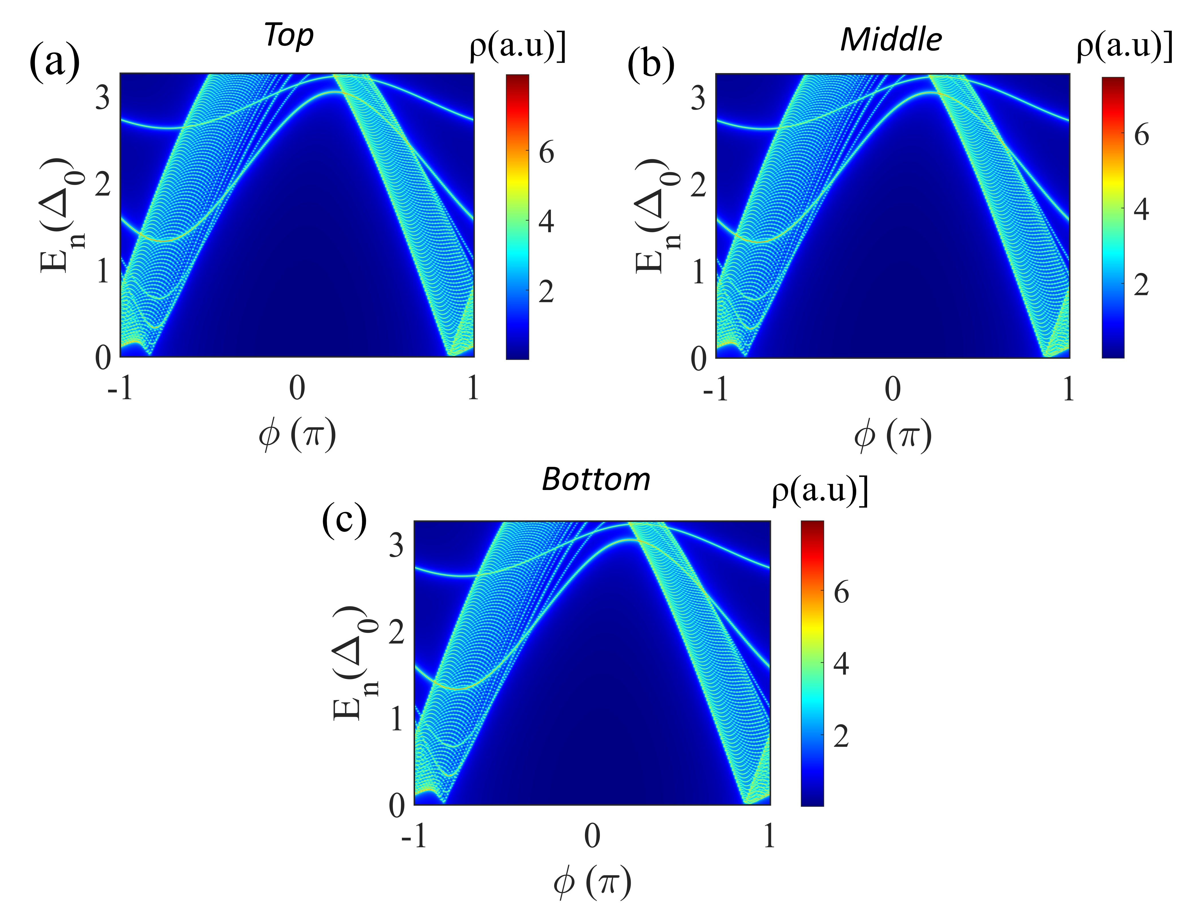
Next, we look at the LDOS to identify the behavior of ABS in the vicinity of edges. Fig. 9(a) shows the LDOS at the top edge of the channel for a system with leads featuring pairing. We observe a clear asymmetry as is changed which signifies the nonreciprocity of the current density. In Fig. 9(b), we show the LDOS calculated in the middle of the channel, which also reveals the asymmetry and nonreciprocity. However, the pattern of the LDOS is clearly different compared to the LDOS at the top edge. This agrees with the behavior of the current density in Fig. 8 attributed to the presence of edge states. The LDOS at the bottom edge in Fig. 9(c) resembles the LDOS of the top edge. Above behavior is in contrast with Fig. 10 calculated for pairing where we observe similar patterns for the top, bottom, and middle parts, and no signatures of edge states.
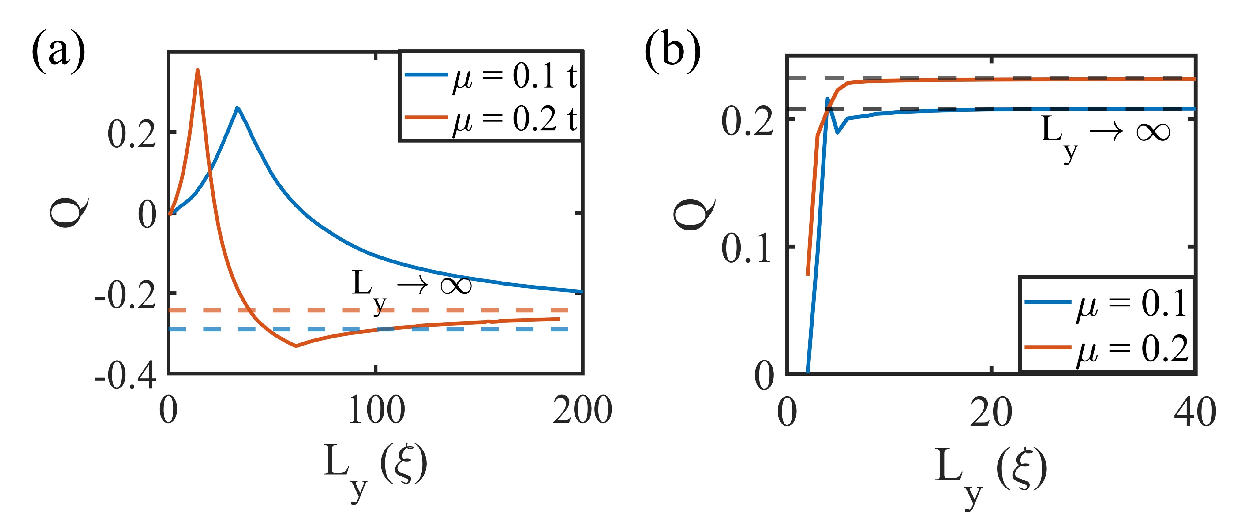
To separate the edge contributions from the bulk contributions, we look at the behavior of as the transverse size is increased. Note that to make the calculation feasible, we had to choose unrealistically large value of the pairing potential . Figure 11(a) shows that in case of pairing, a JJ with a relatively narrow channel () exhibits interplay of the edge and bulk contributions where reaches a maximum. As is increased further, the bulk current contribution becomes dominant, which results in the sign reversal of . We eventually get close to the asymptotic value corresponding to where is calculated using the Fourier transform approach that ignores the edge contributions. In comparison, for a similar calculation with leads featuring the pairing, the asymptotic limit of the channel width is reached very quickly (), as shown in Fig. 11(b).
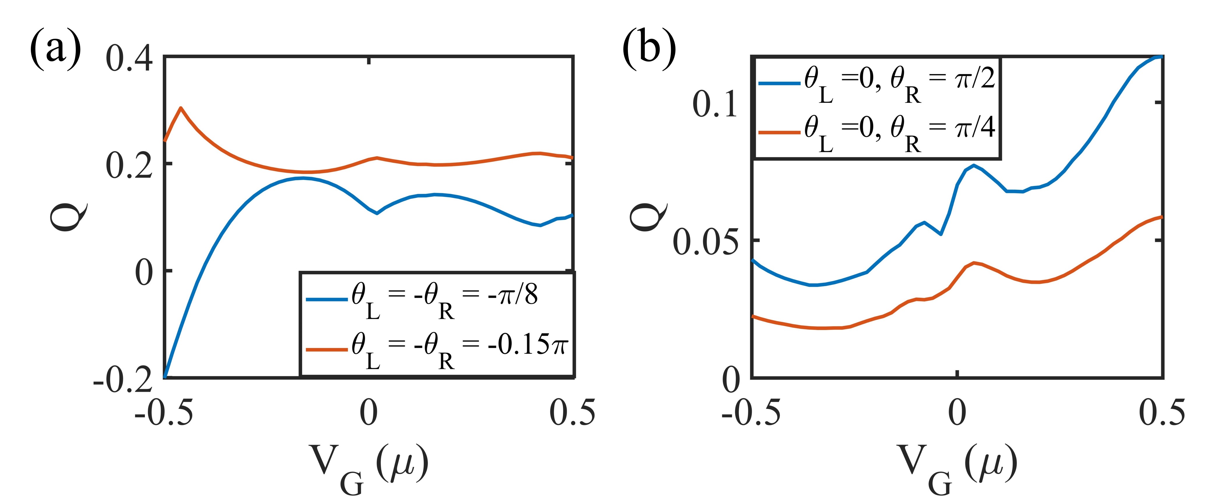
Similar to the JJ considered in the previous section, the systems featuring pairing can be tuned by a gate potential in the normal region. This is demonstrated in Fig. 13 where is calculated as a function of the gate potential . The strong dependence on the gate voltage is observed for and that are in the vicinity of points where changes sign in Fig. 6(a), as can be seen by comparing different curves in Figs. 13(a) and (b). We can achieve tunability and even the sign change, thus replicating the transistor functionality.
VI Leads with pairing
Finally, we consider a ballistic JJ with superconducting leads featuring the pairing. Figure 12 (a) shows the quality factor as a function of the orientation angles and . For a N JJ, we observe in Fig. 12(a) that there is no JDE for orientations described by or , which is consistent with our symmetry analysis. The vanishing JDE for orientations described by is in contrast with the case of pairing in Fig. 6(a), and can be used as a signature to distinguish between the two types of pairings experimentally. The quality factror a for N JJ can be obtained from Fig. 12(a) by a transformation or . This follows from Eq. (II) as the transformation changes to . In Fig. 6(b), we study the variation of with the junction length and find that the quality factor decreases by a factor of two for a longer junction. Furthermore, the presence of SOC only leads to minor changes. In Figs 8(f, g), we examine the current distribution along the transverse direction for a JJ of finite width . In Fig. 8(f) for a N JJ, we observe a uniform distribution of current along the direction for orientation angles and . In Fig. 8(g) for orientation angles , we observe only a minor difference between the edge and the bulk and a vanishing diode effect. To further identify the differences between and pairings, we study the width dependence of JDE in Fig. 11. For the case in Fig. 11(b), we observe that JDE quickly reaches the asymptotic value, which is consistent with the absence of edge contributions for pairing. In Fig. 13(b), we study how a JJ with pairing can be tuned by a gate potential in the normal region. As in the previously considered cases, we observe that the qualuity factor can be tuned by the gate voltage , especially for orientation angles and in Fig. 12(b) corresponding to the sign change of .
VII Conclusions
In this work, we have studied JDE in SNS Josephson junction formed using 2DEG and superconductors with , , and superconducting pairings. We have shown that the quality factor and its sign can be substantially tuned by the external magnetic field, gate voltage, and the length of the junction for all three types of pairings. We have demonstrated that due to the intrinsic TRS breaking in and superconductors, we can realize field-free JDE, where even a relatively small TRS-breaking superconducting pairing component can result in a large JDE. In particular, by breaking certain rotational symmetries a large JDE is possible in the absence of the Zeeman field and SOC. By calculating LDOS and the current distribution inside the normal region, we have also studied the role of edge states associated with pairing. We see clear signatures of the edge states in systems with pairing where the edge currents can have a significant contributions to JDE. We find that JDE vanishes in systems with and pairings under different symmetry constraints. This leads us to the conclusion that JDE can be used to differentiate between different superconducting pairings. Our proposal can be useful for superconductor rectification and realizations of transistor-like functionalities, e.g., also using magnetic textures [49, 50], in superconducting devices operating at low temperatures.
Acknowledgements.
This work was supported by the National Science Foundation/EPSCoR RII Track-1: Emergent Quantum Materials and Technologies (EQUATE), Award OIA-2044049.References
- Ando et al. [2020] F. Ando, Y. Miyasaka, T. Li, J. Ishizuka, T. Arakawa, Y. Shiota, T. Moriyama, Y. Yanase, and T. Ono, Nature 584, 373–376 (2020).
- Miyasaka et al. [2021] Y. Miyasaka, R. Kawarazaki, H. Narita, F. Ando, Y. Ikeda, R. Hisatomi, A. Daido, Y. Shiota, T. Moriyama, Y. Yanase, and T. Ono, Appl. Phys. Express 14, 073003 (2021).
- Zhang et al. [2020] E. Zhang, X. Xu, Y.-C. Zou, L. Ai, X. Dong, C. Huang, P. Leng, S. Liu, Y. Zhang, Z. Jia, X. Peng, M. Zhao, Y. Yang, Z. Li, H. Guo, S. J. Haigh, N. Nagaosa, J. Shen, and F. Xiu, Nat Commun 11, 5634 (2020).
- Wakatsuki et al. [2017] R. Wakatsuki, Y. Saito, S. Hoshino, Y. M. Itahashi, T. Ideue, M. Ezawa, Y. Iwasa, and N. Nagaosa, Sci. Adv. 3, e1602390 (2017).
- Lyu et al. [2021] Y.-Y. Lyu, J. Jiang, Y.-L. Wang, Z.-L. Xiao, S. Dong, Q.-H. Chen, M. V. Milošević, H. Wang, R. Divan, J. E. Pearson, P. Wu, F. M. Peeters, and W.-K. Kwok, Nat Commun 12, 2703 (2021).
- Narita et al. [2022] H. Narita, J. Ishizuka, R. Kawarazaki, D. Kan, Y. Shiota, T. Moriyama, Y. Shimakawa, A. V. Ognev, A. S. Samardak, Y. Yanase, and T. Ono, Nat. Nanotechnol. 17, 823–828 (2022).
- Strambini et al. [2022] E. Strambini, M. Spies, N. Ligato, S. Ilić, M. Rouco, C. González-Orellana, M. Ilyn, C. Rogero, F. S. Bergeret, J. S. Moodera, P. Virtanen, T. T. Heikkilä, and F. Giazotto, Nat Commun 13, 2431 (2022).
- He et al. [2022a] J. J. He, Y. Tanaka, and N. Nagaosa, New J. Phys. 24, 053014 (2022a).
- Tanaka et al. [2022] Y. Tanaka, B. Lu, and N. Nagaosa, Phys. Rev. B 106, 214524 (2022).
- Wu et al. [2022] H. Wu, Y. Wang, Y. Xu, P. K. Sivakumar, C. Pasco, U. Filippozzi, S. S. P. Parkin, Y.-J. Zeng, T. McQueen, and M. N. Ali, Nature 604, 653–656 (2022).
- Nadeem et al. [2023] M. Nadeem, M. S. Fuhrer, and X. Wang, Nat Rev Phys 5, 558–577 (2023).
- Bocquillon et al. [2016] E. Bocquillon, R. S. Deacon, J. Wiedenmann, P. Leubner, T. M. Klapwijk, C. Brüne, K. Ishibashi, H. Buhmann, and L. W. Molenkamp, Nat. Nanotechnol. 12, 137–143 (2016).
- Pal et al. [2022] B. Pal, A. Chakraborty, P. K. Sivakumar, M. Davydova, A. K. Gopi, A. K. Pandeya, J. A. Krieger, Y. Zhang, M. Date, S. Ju, N. Yuan, N. B. M. Schröter, L. Fu, and S. S. P. Parkin, Nat. Phys. 18, 1228–1233 (2022).
- Baumgartner et al. [2022] C. Baumgartner, L. Fuchs, A. Costa, J. Picó-Cortés, S. Reinhardt, S. Gronin, G. C. Gardner, T. Lindemann, M. J. Manfra, P. E. Faria Junior, D. Kochan, J. Fabian, N. Paradiso, and C. Strunk, J. Phys.: Condens. Matter 34, 154005 (2022).
- Gupta et al. [2023] M. Gupta, G. V. Graziano, M. Pendharkar, J. T. Dong, C. P. Dempsey, C. Palmstrøm, and V. S. Pribiag, Nat Commun 14, 3078 (2023).
- Zhang et al. [2022] Y. Zhang, Y. Gu, P. Li, J. Hu, and K. Jiang, Phys. Rev. X 12, 041013 (2022).
- Misaki and Nagaosa [2021] K. Misaki and N. Nagaosa, Phys. Rev. B 103, 245302 (2021).
- Kopasov et al. [2021] A. A. Kopasov, A. G. Kutlin, and A. S. Mel’nikov, Phys. Rev. B 103, 144520 (2021).
- He et al. [2022b] J. J. He, Y. Tanaka, and N. Nagaosa, New J. Phys. 24, 053014 (2022b).
- Daido et al. [2022] A. Daido, Y. Ikeda, and Y. Yanase, Phys. Rev. Lett. 128, 037001 (2022).
- Yuan and Fu [2022] N. F. Q. Yuan and L. Fu, Proc Natl Acad Sci 119, e2119548119 (2022).
- Ilić and Bergeret [2022] S. Ilić and F. S. Bergeret, Phys. Rev. Lett. 128, 177001 (2022).
- Halterman et al. [2022] K. Halterman, M. Alidoust, R. Smith, and S. Starr, Phys. Rev. B 105, 104508 (2022).
- Karabassov et al. [2022] T. Karabassov, I. V. Bobkova, A. A. Golubov, and A. S. Vasenko, Phys. Rev. B 106, 224509 (2022).
- Souto et al. [2022] R. S. Souto, M. Leijnse, and C. Schrade, Phys. Rev. Lett. 129, 267702 (2022).
- Fominov and Mikhailov [2022] Y. V. Fominov and D. S. Mikhailov, Phys. Rev. B 106, 134514 (2022).
- Braginski [2018] A. I. Braginski, J Supercond Nov Magn 32, 23–44 (2018).
- Rymarz et al. [2021] M. Rymarz, S. Bosco, A. Ciani, and D. P. DiVincenzo, Phys. Rev. X 11, 011032 (2021).
- Oh et al. [2021] M. Oh, K. P. Nuckolls, D. Wong, R. L. Lee, X. Liu, K. Watanabe, T. Taniguchi, and A. Yazdani, Nature 600, 240–245 (2021).
- Cao et al. [2018] Y. Cao, V. Fatemi, S. Fang, K. Watanabe, T. Taniguchi, E. Kaxiras, and P. Jarillo-Herrero, Nature 556, 43–50 (2018).
- Gong et al. [2017] X. Gong, M. Kargarian, A. Stern, D. Yue, H. Zhou, X. Jin, V. M. Galitski, V. M. Yakovenko, and J. Xia, Sci. Adv. 3, e1602579 (2017).
- Sigrist [1998] M. Sigrist, Progress of Theoretical Physics 99, 899–929 (1998).
- Can et al. [2021] O. Can, T. Tummuru, R. P. Day, I. Elfimov, A. Damascelli, and M. Franz, Nat. Phys. 17, 519–524 (2021).
- Zhao et al. [2023] S. Y. F. Zhao, X. Cui, P. A. Volkov, H. Yoo, S. Lee, J. A. Gardener, A. J. Akey, R. Engelke, Y. Ronen, R. Zhong, G. Gu, S. Plugge, T. Tummuru, M. Kim, M. Franz, J. H. Pixley, N. Poccia, and P. Kim, Science 382, 1422–1427 (2023).
- Wang et al. [2023] H. Wang, Y. Zhu, Z. Bai, Z. Wang, S. Hu, H.-Y. Xie, X. Hu, J. Cui, M. Huang, J. Chen, Y. Ding, L. Zhao, X. Li, Q. Zhang, L. Gu, X. J. Zhou, J. Zhu, D. Zhang, and Q.-K. Xue, Nat Commun 14, 5201 (2023).
- Margalit et al. [2022] G. Margalit, B. Yan, M. Franz, and Y. Oreg, Phys. Rev. B 106, 205424 (2022).
- Tummuru et al. [2022] T. Tummuru, S. Plugge, and M. Franz, Phys. Rev. B 105, 064501 (2022).
- Song et al. [2022] X.-Y. Song, Y.-H. Zhang, and A. Vishwanath, Phys. Rev. B 105, L201102 (2022).
- Vakili et al. [2023] H. Vakili, M. Ali, M. Elekhtiar, and A. A. Kovalev, Phys. Rev. B 108, L140506 (2023).
- Wu et al. [2017] J. Wu, H. Yuan, M. Meng, C. Chen, Y. Sun, Z. Chen, W. Dang, C. Tan, Y. Liu, J. Yin, Y. Zhou, S. Huang, H. Q. Xu, Y. Cui, H. Y. Hwang, Z. Liu, Y. Chen, B. Yan, and H. Peng, Nat. Nanotechnol. 12, 530 (2017).
- Asano [2001] Y. Asano, Phys. Rev. B 63, 052512 (2001).
- Lu et al. [2023] B. Lu, S. Ikegaya, P. Burset, Y. Tanaka, and N. Nagaosa, Phys. Rev. Lett. 131, 096001 (2023).
- Ostroukh et al. [2016] V. P. Ostroukh, B. Baxevanis, A. R. Akhmerov, and C. W. J. Beenakker, Phys. Rev. B 94, 094514 (2016).
- Zuo et al. [2017] K. Zuo, V. Mourik, D. B. Szombati, B. Nijholt, D. J. van Woerkom, A. Geresdi, J. Chen, V. P. Ostroukh, A. R. Akhmerov, S. R. Plissard, D. Car, E. P. A. M. Bakkers, D. I. Pikulin, L. P. Kouwenhoven, and S. M. Frolov, Phys. Rev. Lett. 119, 187704 (2017).
- de Vries et al. [2018] F. K. de Vries, T. Timmerman, V. P. Ostroukh, J. van Veen, A. J. A. Beukman, F. Qu, M. Wimmer, B.-M. Nguyen, A. A. Kiselev, W. Yi, M. Sokolich, M. J. Manfra, C. M. Marcus, and L. P. Kouwenhoven, Phys. Rev. Lett. 120, 047702 (2018).
- Baumgartner et al. [2021] C. Baumgartner, L. Fuchs, A. Costa, S. Reinhardt, S. Gronin, G. C. Gardner, T. Lindemann, M. J. Manfra, P. E. Faria Junior, D. Kochan, J. Fabian, N. Paradiso, and C. Strunk, Nat. Nanotechnol. 17, 39–44 (2021).
- Legg et al. [2023] H. F. Legg, K. Laubscher, D. Loss, and J. Klinovaja, Phys. Rev. B 108, 214520 (2023).
- Du et al. [2023] B.-H. Du, M. Yang, and L.-B. Hu, Chinese Phys. B 32, 077201 (2023).
- Hess et al. [2023] R. Hess, H. F. Legg, D. Loss, and J. Klinovaja, Phys. Rev. B 108, 174516 (2023).
- Güngördü and Kovalev [2022] U. Güngördü and A. A. Kovalev, J. Appl. Phys. 132, 041101 (2022).