Advancing electron injection dynamics and mitigation approaches in the Electron-Ion Collider’s swap-out injection scheme††thanks: Work supported by Brookhaven Science Associates, LLC under Contract No. DE-SC0012704 with the U.S. Department of Energy
Abstract
The Electron-Ion Collider (EIC) will use swap-out injection scheme for the Electron Storage Ring (ESR) to overcome limitations in polarization lifetime. However, the pursuit of highest luminosity with the required electron bunches encounters stability challenges in the Rapid Cycling Synchrotron (RCS). One method is to inject multiple RCS bunches into a same ESR bucket. In this paper we perform simulation studies investigating proton emittance growth and electron emittance blowup in this injection scheme. Mitigation strategies are explored. These findings promise enhanced EIC stability and performance, shaping potential future operational improvements.
1 Introduction
The EIC, to be constructed at Brookhaven National Laboratory (BNL), is designed to facilitate collisions between polarized high-energy electron beams and hadron beams [willeke2021electron]. The highest luminosity of will be achieved by colliding electrons and protons. The corresponding beam parameters are shown in Table 1. The physics program calls for the simultaneous storage of electron bunches with both spin helicities. A full energy polarized electron injector is needed, so that the electron bunches are injected into the Electron Storage Ring (ESR) with high transverse polarization and the desired spin direction.
| Parameter | Unit | Proton | Electron |
|---|---|---|---|
| Circumference | |||
| Energy | |||
| Particles per bunch | |||
| Crossing angle | |||
| H. RMS emittance | |||
| V. RMS emittance | |||
| H. size | |||
| V. size | |||
| Bunch length | |||
| Energy spread | |||
| H. tune | - | ||
| V. tune | - | ||
| L. tune | - | ||
| H. Damping time | turns | - | |
| V. Damping time | turns | - | |
| L. damping time | turns | - | |
The Rapid Cycling Synchrotron (RCS) will serve as the electron accumulator, ramping electrons from up to . It will be located within the same existing tunnel. The RCS features a -fold lattice periodicity design to avoid spin imperfection and intrinsic resonances, ensuring the maintenance of electron polarization.
Due to the short lifetime of polarization, the ESR injection scheme adopts full bunch swap, necessitating that the RCS provides per bunch, as indicated in Table 1. However, electron bunches with exhibit instability at the lower energy of . There is ongoing consideration regarding the development of a dedicated booster to mitigate this issue [lovelace2023damping]. Nonetheless, achieving per bunch is beyond the state of the art for such boosters [calvey2021measurements].
Another approach involves injecting multiple electron bunches into one same ESR bucket, where synchrotron radiation damping will eventually merge the injected and stored bunches. According to Liouville’s theorem, the injected bunch cannot occupy the same phase-space volume as the stored beam without impacting the latter. Therefore, a separation between the injected and stored beams is necessary. Previous study has demonstrated that proton emittance growth occurs when injection errors are included [qiang:ipac2021-wepab252]. Additionally, the electron emittance is likely to blow up significantly due to the large tune spread resulting from the electromagnetic kick from the opposing proton beam.
In this paper, we will study the feasibility of this injection scheme in presence of beam-beam interaction. The beam parameters used in our simulation is presented in Tab. 1.
2 Betatron vs synchrotron injection
According to the methods at the injection point to separate the injected and stored bunches, we adopt the terms “betatron injection” and “synchrotron injection” as described in [mori2012design].
In betatron injection, the injected bunch is positioned at the same location in the longitudinal phase space and undergoes betatron oscillation due to its initial transverse offset from the design orbit. Conversely, in synchrotron injection, the injected bunch differs in energy from the stored beam, with the two beams separated by a dispersion at the injection point. This leads to the centroid of the injected bunch performing synchrotron oscillation.
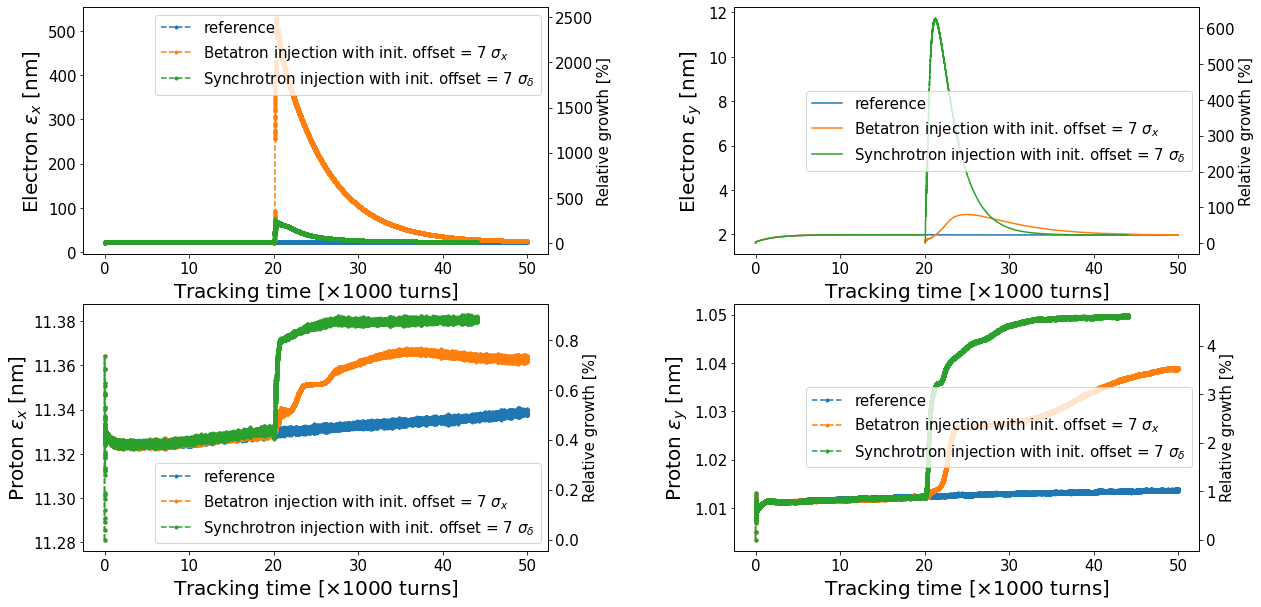
Figure 1 displays the strong-strong simulation results for betatron and synchrotron injection. The old electron bunch is tracked for turns before being kicked out. Subsequently, four electron bunches are injected into the same ESR bucket over a duration of turns. Thanks to the synchrotron radiation, these four newly injected bunches will merge into a single bunch.
At , each electron bunch should be replaced every minutes. The lower two plots in Figure 1 illustrate the evolution of the proton bunch’s emittance. When compared to the blue reference curve without electron replacement, the increase in proton emittance per electron bunch replacement is less than in the horizontal plane and in the vertical plane. Consequently, the increase in proton emittance due to electron replacement remains below per hour, which is acceptable in comparison to the intra-beam scattering (IBS) lifetime of hours.
However, as indicated by the upper two plots in Figure 1, the electron emittance experiences significant change. Specifically, in betatron injection with an initial transverse offset of , the horizontal emittance increases up to times, while in the synchrotron injection scheme with an initial momentum offset of , the vertical emittance rises up to times. The substantial increase in horizontal emittance conflicts with the small dynamic aperture and leads to particle loss. Additionally, the enlarged vertical emittance could enhance intrinsic resonances, potentially leading to depolarization. Therefore, it is necessary to develop strategies to mitigate this electron emittance blowup.
3 Two kicker scheme in betatron injection
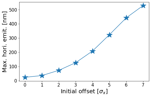
The horizontal emittance blowup in betatron injection can be mitigated by reducing the initial offset. Figure 2 illustrates the maximum horizontal emittance observed during the strong-strong simulation. During the simulation, the initial offset, expressed in terms of , varies while all other conditions remain consistent with those depicted in Fig. 1.
To minimize the initial offset relative to the design orbit while maintaining sufficient separation between the injected and stored bunches, the introduction of a second kicker is proposed. This concept is illustrated in Fig. 3. As the electron bunch loses polarization, the old electron bunch is kicked out. Consequently, when the first bunch is injected, the ESR bucket is empty, allowing the bunch to be injected directly on orbit. For subsequent injections, the stored bunch is shifted to a position with a negative offset at the injection point, while the newly injected bunch is positioned with a positive offset. This arrangement ensures that both bunches maintain a small offset relative to the design orbit and achieve adequate separation to accommodate the septum magnet.
Figure 4 displays the simulation results for the two-kicker scheme, specifically focusing on the electron’s horizontal emittance. The duration between two injections is turns, which is sufficient long to merge the stored and injected beam. In this setup, both the stored and injected bunches are directed to positions of at the interaction point (IP). As a result, the maximum horizontal emittance is reduced to seven times of the design value. Further examination of the phase space output reveals that only of macro-particles exceed the dynamic aperture.
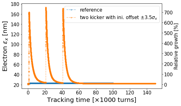
Further reduction of the maximum horizontal emittance is indeed achievable by optimizing the phase advance between the IP and the injection point, as well as by utilizing a pulse quadrupole.
4 Vertical emittance blowup in synchrotron injection
The electron emittance blowup in synchrotron injection can be attributed to synchro-betatron resonance. This phenomenon occurs when an electron bunch is injected with an off-momentum deviation. The momentum offset translates into a longitudinal offset due to longitudinal oscillation. As the bunch goes through the crab cavity, the significant longitudinal offset induces a nonlinear crab kick, resulting in a horizontal offset at the IP. This horizontal displacement is modulated by the longitudinal motion, which in turn excites higher-order synchro-betatron resonances via beam-beam interaction [PhysRevAccelBeams.24.041002].
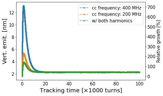
Figure 5 illustrates the vertical emittance evolution through a weak-strong simulation. The vertical emittance blowup is significantly mitigated by selecting a lower frequency for the crab cavity. Utilizing a combination of and frequencies for the crab cavity results in a more linear crab cavity kick, which further reduces the emittance blowup. This approach clearly demonstrates the emittance blowup is caused by synchro-betatron resonance.
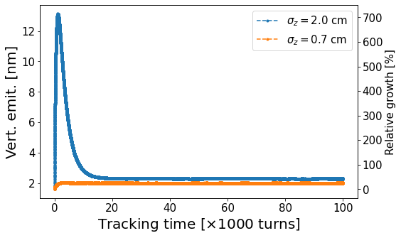
Reducing the longitudinal action can effectively decrease the strength of synchro-betatron resonance. Figure 6 shows a comparison of different electron bunch lengths through the weak-strong simulation. The term “bunch length” here refers to the equilibrium length in the absence of beam-beam interaction, which is proportional to the bucket width. When the electron bunch length is reduced to , which is the current design value, the vertical emittance blowup is eliminated.
5 Conclusion
One possible method to accumulate a high electron charge is by injecting multiple electron bunches into the same ESR bucket. This paper investigates betatron and synchrotron injection schemes using both weak-strong and strong-strong simulations. A two-kicker scheme is proposed to mitigate the horizontal emittance blowup in the betatron injection scheme. The vertical emittance blowup in the synchrotron injection scheme can be alleviated by reducing the electron bunch length. Given that a bunch length of is included in the latest baseline design of the ESR, synchrotron injection emerges as a viable method for merging multiple electron bunches into a single bunch within the same bucket.
References
- [1] JACoW, http://www.jacow.org
- [2] IEEE Editorial Style Manual, IEEE Periodicals, Piscataway, NJ, USA, Oct. 2014, pp. 34–52.
- [3] https://woodward.library.ubc.ca/researchhelp/journal-abbreviations/