Two-Plasmon-Decay Instability Stimulated by a Normal- and Large-Angle-Incidence Laser Pair
Abstract
The two-plasmon-decay instability (TPD) is a critical target preheating risk in direct-drive inertial confinement fusion. In this paper, TPD collectively driven by a normal-incidence laser beam (Beam-N) and a large-angle-incidence laser beam (Beam-L) is investigated via particle-in-cell simulations. Significant TPD growth is found able to develop in this regime at previously unexpected low laser intensities if the intensity of Beam-L exceeds the large-angle-incidence threshold. Both beams contribute to the growth of TPD in a “seed-amplification” manner where the absolute instability driven by Beam-L provides the seeds that get convectively amplified by Beam-N, making TPD energetically important and causing significant pump depletion and hot electron generation.
1 Introduction
As the milestone on inertial confinement fusion (ICF) ignition has been achieved[1, 2, 3] in the National Ignition Facility (NIF), higher energy gain is being pursued by the ICF community in the next phase. The direct-drive schemes, in which the high-intensity lasers directly deposit energy to an ICF target, generally have high laser-to-target energy coupling efficiency and are considered as candidates for high-gain fusion approaches.[4] Direct laser interaction with target is not only a key process in the conventional central-hot-spot direct-drive scheme, but is also utilized in one or multiple phases of novel ignition schemes such as the shock ignition[5], the hybrid ignition[6], and the double-cone ignition[7].
One of the critical challenges in the direct-drive ICF is the harmful impacts due to the laser plasma instabilities (LPIs), including stimulated Raman Scattering (SRS), stimulated Brillouin Scattering (SBS), cross beam energy transfer (CBET), and two-plasmon decay (TPD) instability, occurring in the corona plasmas ablated off from the target shell. As the laser propagates through a direct-drive corona plasma, it experiences a broad range of electron density from vacuum up to the critical density () beyond which a laser is not able to propagate. In this scenario, the quarter-critical density () areas, where TPD and the absolute SRS can be parametrically stimulated, are usually located in a less collisional plasmas consisting of low-Z ablator materials and therefore are of critical concern. The LPI processes near are of less concern in an indirect-drive hohlraum since the areas are usually located in a high-Z gold plasma where the heavy collisional damping inhibits TPD or SRS growths there. LPIs can not only cause direct energy loss through the processes involving scattered lights, i.e., SRS, SBS, and CBET, but also cause fuel preheating threats through the energetic (hot) electrons produced via TPD and SRS which involve electron plasma waves(EPWs) that are able to accelerate electrons.
Through TPD a laser parametrically decays into a pair of the so-called daughter EPWs. TPD is considered as a critical LPI impacting the implosion performance in direct drive due to its low threshold[8, 9, 10] and hot electron generation[11, 12]. TPD has been identified as the primary source of hot electrons which can preheat the fuel[4, 11] and compromise the implosion performance on the OMEGA direct-drive facility.
While the modern ignition facilities generally use multiple overlapping laser beams, much of the knowledge on TPD was firstly established in simplified single-beam regimes.[8, 9, 12, 13, 14, 15, 16, 17, 18] The threshold for TPD growth in an inhomogeneous plasma with a linear density profile in a normal-incidence regime [i.e., the laser propagation direction is along the electron density () gradient ] was obtained[9] as
| (1) |
where is the electron density scale length at in the unit of microns, is the laser wavelength in vacuum () in microns, is the laser intensity () in the unit of , and is the electron temperature () in . In references [17, 18] two different types of modes, absolute and convective, were identified via fluid simulations based on their distinguished growth behaviors in a linear system. Absolute modes grow exponentially with time while convective modes have limited factors of amplification on the initial seeds. However, the convective modes were found energetically important in the simulations[17] due to the nonlinearity involving ion dynamics[12, 15, 16, 17]therefore both absolute and convective modes saturate forming quasi-static broad EPW spectra up to the Landau cutoff in the space. Broad spectra of the emission associated with the TPD EPWs have been consistently observed in OMEGA experiments[19], where is the laser frequency.
It has been well recognized that TPD can be collectively driven by multiple overlapping lasers. The total energy in hot electrons was shown experimentally to scale with the overlapped intensity on OMEGA.[20] The threshold condition of Eq.(1) which has been largely verified by the fluid simulations[18] also works empirically well predicting the onset of TPD in OMEGA experiments if using the overlapped intensity to calculate .[19] These works evidenced that TPD is highly unlikely to be independently driven by each individual laser beam. Deliberate experiments were then carried out to investigate the growths of the shared daughter plasma waves (often referred to as the common waves) contributed by multiple laser beams.[21, 22] It was evidenced that laser beams can drive the common waves in the region of wave numbers bisecting the beams and the convective gain is proportional to the overlapped laser intensity.[21] Moreover, the hot electron fraction was found to increase exponentially with the overlapped laser intensity in the experiments under various beam configurations. [22] Three dimensional (3D) simulations further showed that the threshold for the absolute TPD modes driven by multiple beams is significantly lower than the expected single-beam value. [23]
An important factor that can contribute to the low threshold found in reference [23] comes from the oblique incidence angles. The single-beam threshold intensity of TPD under moderate incidence angles was found to be lowered by a factor of .[24], where is the angle between the local laser wave vector and near . Large incidence angles, however, lower the absolute TPD threshold even more drastically. [25, 26] To clarify, the incidence angle () is referred to as the angle between and in this paper, where is the laser wave vector in vacuum with the magnitude and is the speed of light in vacuum. The regime where is close to or even larger is considered as the large-angle-incidence regime. Based on theoretical modeling and fluid simulation using LTS [18], Lian et al. [25] proposed a threshold for the absolute TPD growth in the large-angle-incidence regime with :
| (2) |
which was also found consistent with the PIC simulations[25]. This large-angle-incidence TPD threshold was shown to be two orders of magnitude lower than that of the normal incidence with ICF-relevant parameters.[25] Moreover, the simulations on TPD induced by multiple beams all with also exhibited low threshold and common-wave processes which largely depend on the lasers’ polarization.[26]
The very low TPD threshold in the large-angle-incidence regime brings attention to TPD in a sophisticated laser-plasma system where virtually all incidence angles are present and a portion of plasma can be simultaneously irradiated by both small- and large-angle-incidence beams. Whether the large-angle-incidence TPD which can be driven at low laser intensities can cause destabilizing effects in the whole system is an open question.
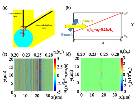
In this paper, we study TPD in a simpler but typical “N-L” two-beam system composed of a Normal-incidence beam (Beam-N) and a Large-angle-incidence beam (Beam-L) via numerical simulations. The schematic of an N-L system in direct drive is illustrated in figure 1(a). Although each beam in direct drive is generally pointed to the target center, the off-axis part of the laser with weaker intensity than the peak value can glance at the edge part of the corona plasma surrounding the target. Therefore the zone inside the box in figure 1(a) can be recognized to be irradiated by a higher intensity Beam-N and a lower-intensity Beam-L. N-L systems typically exist in many direct-drive schemes such as the conventional central-hot-spot ignition scheme [4], the shock ignition[5, 27], and the double-cone ignition[7]. The rest of this paper is organized as follows: In Sec. II, we describe the simulation set-up. The development of TPD in an N-L configuration is investigated in Sec. III and the generation of hot electrons is discussed in Sec. IV. A summary is presented in Sec. V.
2 Simulation configurations
A series of Particle-in-Cell(PIC) simulations are performed using a full PIC code [28] to investigate the LPI processes in the boxed zone in figure 1(a). The schematic of a typical simulation box is illustrated in figure 1(b). The parameters are chosen relevant to OMEGA and SG direct-drive experiments. The plasma has a linear electron density profile as and a uniform electron temperature , where the electron density scale length is set as in all of the simulations cases in this paper. The ions are composed of fully ionized CH (plastic) with the number ratio and the temperature unless otherwise noted. The electron-ion collisions are included. Two laser beams, ie., Beam-N and Beam-L, are launched from the left side with a rising time and at the incident angles and , respectively. Different combinations of the laser intensities of Beam-N () and Beam-L () are explored and the detailed parameters are listed in TABLE 1. Since Beam-L is abstracted from the off-axis part of an actual laser beam [see figure 1(a)], it is physical to set much weaker than . Both beams are linearly polarized in the plane.
The simulation box size is with a grid of , yielding the grid size . For each species (electrons and ions), 100 particles per cell are used. The simulation domain is periodic in . Open boundary conditions are applied to the electromagnetic fields in the direction. The “thermal-bath” boundary conditions, which reflect the particles reaching the boundary and assign them with new random velocities following the initial Maxwellian distribution, are applied to the particles in the direction.
3 Growth of TPD in the N-L system
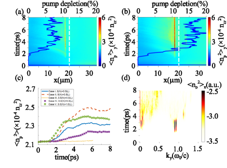
The simulation parameters are chosen such that is well below the threshold namely such that the normal-incidence Beam-N is not intense enough to excite TPD by itself. Beam-L is close to glancing incidence near the turning point approximately located at . The laser fields in Case I are shown in figure 1(c). In this case , indicating that Beam-L is well above the TPD threshold and able to drive absolute growth in the large-incidence-angle regime if shined alone. It should be noted that the “overlapping ” () calculated by substituting into Eq.(1) are also below unity in all of the cases, as listed in TABLE 1. A snapshot of the electron density fluctuations () associated with EPWs in Case I is illustrated in figure 1(d), and the time and space evolution of is illustrated in figure 3(a). Here the bracket represents averaging over . It is shown that EPWs with notable amplitude are driven near 0.25 and last throughout the simulation. Those EPWs are attributed to TPD instead of SRS, since virtually no SRS scattered light appears in the spectrum of the component of magnetic fields () which is associated with the lights. The presence of the large-incidence-angle Beam-L is identified as the key factor enabling TPD growth in Case I, as no TPD is observed if we redistribute all the intensity from Beam-L to Beam-N while maintaining the same (see Case III of TABLE 1).
Once TPD is able to grow, it can be energetically important and cause significant pump depletion in the N-L system. Figure 2(a) demonstrates the pump-depletion fraction of Beam-N in Case I. Roughly 7% of the Beam-N energy is depleted once TPD is stimulated, which evidences that Beam-N also participates in the TPD process. Changing the intensity of either Beam-L or Beam-N is found to change the pump depletion fraction and , which can be used to assess the level of TPD. Here is the averaged value of over the whole simulation domain. In Case II the intensity of Beam-N is increased to corresponding to which is still lower than the normal threshold, while the intensity of Beam-L is kept the same as in Case I. The pump-depletion of Beam-N rises to roughly 15%. It should be pointed out that the energy Beam-N loses can be even higher than the input energy of Beam-L. In Cases III, IV, and V different are used while keeping the same as in Case I to further demonstrate the sensitive dependence of TPD on the fairly low intensity Beam-L. Figure 2(c) compares with different intensities of Beam-N and Beam-L. It is shown that saturates to quasi-steady values after a few ps growing. It is also shown that raising either or leads to higher TPD levels and the absence of Beam-L (Case III) completely turns TPD off. Both the influence from the low-intensity Beam-L and the significant pump depletion of the high-intensity Beam-N are evidencing that TPD is collectively driven by both beams.
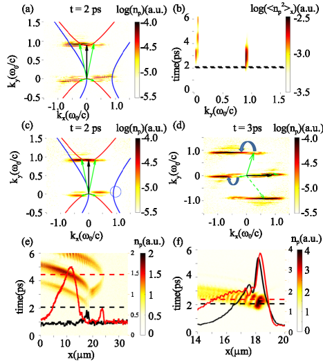
The electron density perturbation in Case I is displayed in the space to illustrate the evolution of EPWs from the linear growing stage up to the highly nonlinear stage [see figure 2(d)]. The narrow-band EPW spectra concentrated near and in the early linear stage become much broader in in the highly nonlinear stage. The modes initially growing in the linear stage are attributed to Beam-L. The dispersion relation for single-beam TPD growing in homogeneous plasmas predicts the well-known fastest-growing hyperbola [29] shown by the solid curves in figure 3(a), red for Beam-L and blue for Beam-N, respectively. The dominant modes laying on top of the red hyperbola also satisfy the wave vectors’ matching condition illustrated by the arrows:
| (3) |
where and (the green arrows) are the wave vectors of the paired daughter EPWs, is the local wave vector of Beam-L (the black arrow), which is propagating along the direction near its reflecting point.
The individual roles of the two beams in developing TPD in the N-L system are further demonstrated by separating their time windows in Case VI. In Case VI Beam-L is set to be incident from to 2 ps while the onset of Beam-N is set on ps such that they barely overlap in time. All the other simulation parameters are kept essentially the same as Case I, except that the ions are fixed in Case VI to inhibit nonlinear effects brought in by the ion dynamics. The time evolution of the spectrum of is illustrated in figure 3(b). It is shown that similar to Case I in linear stage [see figure 2(d)] the dominant modes in Case VI are located at and , respectively. We then call the modes with the small- modes, the modes with the large- modes. The large- modes are able to grow to a substantial level before the onset of Beam-N, evidencing that the large- modes can be stimulated by the Beam-L alone. During the incidence of Beam-N (2 ), the amplitudes of the large- modes get further amplified and then decay after 4 ps. The amplification after 2 ps shows that Beam-N transports energy to the large- modes while the decay after 4 ps shows that Beam-N by itself cannot maintain the level, which is a feature of a convective amplification.
The evolution of the large- modes in Case VI can be divided into two phases: excitation by Beam-L and amplification by Beam-N. The spectra of the EPWs in Case VI in the space are depicted in figure 3(c) at ps and figure 3(d) at ps to illustrate the TPD matching conditions and the dominant modes’ shifting at different phases. In the excitation phase [see figure 3(c)], the spectrum of Case VI exhibiting both the large- and small- modes are similar to that of Case I [figure 3(a)]. It demonstrates that Beam-L itself can stimulate the large- and small- modes simultaneously, which satisfy the wave vectors’ matching condition of equation (3) sketched with the solid arrows. Compared to figure 3(a), the spectrum in figure 3(c) misses a portion near the blue hyperbola due to the lack of Beam-N, as marked by the blue circle. The missing portion can be seen in figure 3(d) which shows the dominant modes in the amplification phase with Beam-N only. The dominant of both large- and small- modes becomes larger. The dominant modes’ shifting can be attributed to two processes: Firstly, by satisfying its own matching conditions, Beam-N can drive and amplify the paired EPWs (marked by the green dashed arrows) of the existing EPWs (marked by the green solid arrows) excited by Beam-L. Secondly, of the existing EPWs increase as they propagate towards the lower density, denoted by the blue flow arrows. The propagation of the EPWs and the convective amplification on the path for the large- and small- modes are further illustrated in figure 3(e) and (f).
A set of typical small- modes with are localized near m right below 0.25 at ps after the absolute growth in the excitation phase driven by Beam-L only, as shown in figure 3(e). The amplitude of along the black dashed line is plotted in the back solid line to show the location of the dominant modes at ps. Then, instead of continuing to grow locally, the small- modes are found to propagate to different locations and get amplified at certain densities. Three distinguishable propagation paths in figure 3(e) suggest that at ps the small- modes include a range of , leading to different group velocities that sketch different propagation paths on the space. As the small- modes eventually move to lower density due to the electron density gradient, increases since an EPW must satisfy the dispersion relation in plasma while keeps constant as the density is uniform along the direction. The up shift of can be seen in figure 3(d), as marked by the blue flow arrow on the small- modes. The profile of the small- modes at ps along the red dashed line is plotted with the red solid line in figure 3(e), demonstrating the convective amplification of the small- modes by Beam-N.
The convective amplification of a typical large- mode with is shown in figure 3(f). The mode is convectively amplified a bit from ps (black solid line) to ps (red solid line) as the wave package moves forward. Compared with the small- modes, the amplification of this mode is much weaker. The difference in the amplification factor between the large- and small- modes can be estimated with the Rosenbluth-like gain presented in reference [17]:
| (4) |
where the Rosenbluth amplification factor of a mode with different is , is a dimensionless . Landau damping is absent in equation (4). The value gives the same order of magnitude of the amplification factor as that in the PIC simulation of Case VI, i.e. reads from figure 3(c). According to equation (4), the amplification factor with larger is smaller, which is qualitatively consistent with the simulation. However, the gain for the mode with obtained by equation (4) is much larger than the simulation results, likely due to the heavier Landau damping of the EPWs which is not taken into account in equation (4).
Overall, the growth of TPD in the N-L system can be recognized as a “seed-amplification” process where the absolute instability driven by Beam-L provides the seeds that get convectively amplified by Beam-N. The levels of the seeds are mostly determined by Beam-L, while the amplification factors are determined by Beam-N. The two beams contribute to the TPD growth in different ways, both making TPD energetically important in the N-L system, even after the saturation due to the nonlinear effects including ion motions.
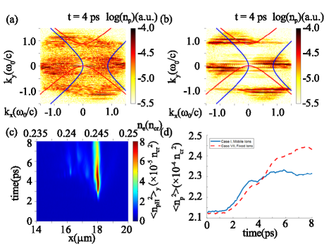
The EPW spectrum in the nonlinear stage at 4 ns is much broader [figure 4(a)] than that in the linear stage [figure 3(a)] of Case I. Spectrum broadening was also found in the simulations on normal-incidence TPD.[12, 17] The ion dynamics are recognized as a key factor in broadening the EPW spectrum. Case VII with immobile ions and virtually the same other configurations as Case I is performed to show the role of the ion motions. Case VII demonstrates a much narrower EPW spectrum than Case I, as shown in figure 4. It was well known that the ion density fluctuations are driven by the ponderomotive pressure of the EPWs and are correlated with the level of EPWs.[17] In Case I where both beams are shining from the very beginning of the simulation, the ion density fluctuations are gradually driven up and mostly localized in a fairly narrow region near 1/4 , where the absolute modes are located, shown in figure 4(c).
The ion motions also contribute to the TPD saturation and limit the EPWs level. Figure 4(d) compares the time evolution of , which quantifies the EPWs level, of Case VII with fixed ions and of Case I with mobile ions. It is shown that TPD in Case I saturates at a lower level after ns when the ion density fluctuations are significant (see figure 4(c)). It was demonstrated experimentally that the ions can saturate TPD via the Langmuir decay instability [30], where a primary TPD EPW decays into an ion acoustic wave and a new EPW. In contrast, TPD in Case IV saturates later and at a higher level, likely due to the convective amplification limits[18, 31] and/or other kinetic saturation mechanisms limiting the EPWs amplitudes. It should be pointed out that including ion motions is critical to correct modeling on TPD saturation, which largely determines the EPWs features and the hot electron generation in the nonlinear stage.
4 Hot electron generation
The hot electron generation is of most concern since the hot electrons generated by TPD are recognized as a significant target preheating risk. Usually, the hot electrons whose kinetic energy is above 50 keV are considered most threatening and therefore paid most attention in our simulations. Both the forward and backward moving instantaneous energy fluxes carried by the hot electron above 50 keV are monitored in the simulations at the right and left boundaries of the simulation box as and , respectively. Here and have been renormalized to the incident laser energy flux including both beams. Then can be recognized as the energy conversion fraction from laser to the hot electrons 50 keV.
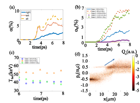
From the time evolution of ’s in Case I as shown in figure 5(a), substantial laser energy can be transferred to the hot electrons, mostly in the nonlinear stage after ps. increases sharply at about ps and reaches a notable level later in the nonlinear stage, which is correlated with the result that the pump depletion of Beam-N reaches high levels after about 3 ps as plotted in figure 2 (a). This correlation evidences that the majority of the hot electron energy comes from Beam-N. is of more concern as it moves forward to the high density side toward the center of an ICF target, causing direct preheating. is found smaller than as shown in figure 5(a) yet is still alerting as is much larger than the tolerable hot-electron preheating in direct drive [4].
Increasing the intensity of either Beam-N or Beam-L is found to enhance the hot electron fluxes in the N-L system, as demonstrated by figure 5 (b). The intensity of Beam-N increases from in Case I to in Case II, causing to increase from to in the nonlinear stages after ps. Increasing the intensity of Beam-L in Case I to in Case V causes to rise from to about , while lowering down to in Case IV reduces down to . These trends are evidencing that enhancing either “amplification” or “seed” in the N-L system would enhance the hot electron generation and vice versa. It is also shown in figure 5(b) that the absence of Beam-L in Case III () completely suppresses TPD and produces no hot electrons even if is larger than that in Case I, which shows that the absolute growth driven by Beam-L is a must for hot electron generation in this regime. Lowering is proposed to be a good strategy for mitigating the hot electron fluxes in the N-L system since it does not need to alter the total input laser energy very much.
Other than the energy fluxes, the temperature () that determines the penetration depth is another key feature of the hot electrons from the target-preheating point of view. In the simulations, is obtained by Maxwellian fitting of the high energy tail in the electron distribution function.[32] is found to reach a quasi-steady value in the highly nonlinear stage of each case as shown in figure 5(c). Figure 5(c) also shows that largely depends on but is not that sensitive to . In the nonlinear stage reaches about 40 keV in Case I. Increasing to (Case II) causes to rise to 50 keV. However, is found very similar (about 40 keV) in Cases I and V where is kept the same while is quite different in the two cases. Staged acceleration of hot electrons in Case I is demonstrated in figure 5 (d) as it shows that the maximum longitudinal momentum of the hot electrons increases from smaller to larger (indicated by the blue arrow). The staged acceleration process is similar to that in the single-beam normal-incidence regime reported in reference [12]: The EPWs in the low-density region have low phase velocities that allow effective first-stage acceleration of thermal electrons. Then the electrons are staged accelerated by the EPWs with higher phase velocities in the higher-density region.
The scaling laws obtained through numerical fitting of comprehensive PIC simulations [33] have been reported to well predict for the cases in the single-beam normal-incidence regime. Although the two-beam N-L regime with is certainly beyond the aimed scope fo equation (2) of reference [33], this formula is still arguably adapted to predict in an N-L regime since Beam-L can be considered as a small energy perturbation added to the single-beam normal-incidence system including Beam-N only. Equation (2) of reference [33] predicts keV for Case I, larger than the simulation value keV. Better agreement is reached for larger . Lower poses lower preheating risk, but still, the unexpected TPD growth in the N-L regime when is well below unity is an uncertainty to direct-drive ICF.
5 Summary and discussions
To summarize, TPD driven by two laser beams in an N-L system has been investigated through PIC simulations. It is shown that in the presence of a low-intensity Beam-L that exceeds its large-angle-incidence TPD threshold (), significant TPD growth is able to be driven in a regime where is well below unity. Both beams contribute to the growth of TPD via the “seed-amplification” process where the absolute instability driven by Beam-L provides the seeds that get convectively amplified by Beam-N. The levels of the seeds are mostly determined by Beam-L, while the amplification factors are determined by Beam-N. The two beams contribute to the TPD growth in different ways, both making TPD energetically important and causing significant pump depletion as well as hot electron generation in the N-L system. The hot electron fluxes are found depending on the intensities of both beams while the hot electron temperature is found mostly depending on the intensity of Beam-N.
The low threshold of TPD in this regime can be harmful to direct-drive ICF and place extra confinement on target design, as TPD is able to grow significantly in previously unexpected regions. In experimental conditions, Beam-L comes from a laser’s side part that glances at the edge of the corona plasma. Therefore, to lower the risk of TPD, it would be a good strategy to shrink the width of each laser spot, which has already been well known to benefit the implosion performance by mitigating CBET.[34, 35, 36] Reducing the spot sizes can help lower in the N-L system illustrated in figure 1(a), thereby mitigate the two-beam TPD as another pro to direct-drive ICF.
Acknowledgment
We thank the UCLA-IST OSIRIS Consortium for the use of . This research was supported by the National Natural Science Foundation of China (NSFC) under Grant Nos. 12375243 and 12388101, by the Strategic Priority Research Program of Chinese Academy of Sciences under Grant Nos. XDA25050400 and XDA25010200, by the Science Challenge Project, and by the Fundamental Research Funds for the Central Universities. The numerical calculations in this paper have been done on the supercomputing system in the Supercomputing Center of University of Science and Technology of China.
References
References
- [1] AB Zylstra, OA Hurricane, DA Callahan, AL Kritcher, JE Ralph, HF Robey, JS Ross, CV Young, KL Baker, DT Casey, et al. Burning plasma achieved in inertial fusion. Nature, 601(7894):542–548, 2022.
- [2] H Abu-Shawareb, R Acree, P Adams, J Adams, B Addis, R Aden, P Adrian, BB Afeyan, M Aggleton, L Aghaian, et al. Lawson criterion for ignition exceeded in an inertial fusion experiment. Phys. Rev. Lett., 129(7):075001, 2022.
- [3] R Betti. A milestone in fusion research is reached. Nature Reviews Physics, 5(1):6–8, 2023.
- [4] R. S. Craxton, K. S. Anderson, T. R. Boehly, V. N. Goncharov, D. R. Harding, J. P. Knauer, R. L. McCrory, P. W. McKenty, D. D. Meyerhofer, J. F. Myatt, A. J. Schmitt, J. D. Sethian, R. W. Short, S. Skupsky, W. Theobald, W. L. Kruer, K. Tanaka, R. Betti, T. J. B. Collins, J. A. Delettrez, S. X. Hu, J. A. Marozas, A. V. Maximov, D. T. Michel, P. B. Radha, S. P. Regan, T. C. Sangster, W. Seka, A. A. Solodov, J. M. Soures, C. Stoeckl, and J. D. Zuegel. Direct-drive inertial confinement fusion: A review. Phys. Plasmas, 22(11):110501, 2015.
- [5] R. Betti, C. D. Zhou, K. S. Anderson, L. J. Perkins, W. Theobald, and A. A. Solodov. Shock ignition of thermonuclear fuel with high areal density. Phys. Rev. Lett., 98:155001, 2007.
- [6] X. T. He, J. W. Li, Z. F. Fan, L. F. Wang, J. Liu, K. Lan, J. F. Wu, and W. H. Ye. A hybrid-drive nonisobaric-ignition scheme for inertial confinement fusion. Phys. Plasmas, 23(8):082706, 2016.
- [7] J. Zhang, W. M. Wang, X. H. Yang, D. Wu, Y. Y. Ma, J. L. Jiao, Z. Zhang, F. Y. Wu, X. H. Yuan, Y. T. Li, and J. Q. Zhu. Double-cone ignition scheme for inertial confinement fusion. Philosophical Transactions of the Royal Society A: Mathematical, Physical and Engineering Sciences, 378(2184), 2020.
- [8] C. S. Liu and Marshall N. Rosenbluth. Parametric decay of electromagnetic waves into two plasmons and its consequences. Physics of Fluids, 19(7):967–971, 1976.
- [9] A. Simon, R. W. Short, E. A. Williams, and T. Dewandre. On the inhomogeneous two-plasmon instability. Physics of Fluids, 26(10):3107, 1983.
- [10] Bedros B. Afeyan and Edward A. Williams. A variational approach to parametric instabilities in inhomogeneous plasmas iii: Two-plasmon decay. Phys. Plasmas, 4(11):3827, 1997.
- [11] V. A. Smalyuk, D. Shvarts, R. Betti, J. A. Delettrez, D. H. Edgell, V.Yu. Glebov, V. N. Goncharov, R. L. McCrory, D. D. Meyerhofer, P. B. Radha, S. P. Regan, T. C. Sangster, W. Seka, S. Skupsky, C. Stoeckl, B. Yaakobi, J. A. Frenje, C. K. Li, R. D. Petrasso, and F. H. Sguin. Role of hot-electron preheating in the compression of direct-drive imploding targets with cryogenic d2 ablators. Phys. Rev. Lett., 100(18):185005, 2008.
- [12] R. Yan, C. Ren, J. Li, A. V. Maximov, W. B. Mori, Z.-M. Sheng, and F. S. Tsung. Generating energetic electrons through staged acceleration in the two-plasmon-decay instability in inertial confinement fusion. Phys. Rev. Lett., 108:175002, 2012.
- [13] A. Bruce Langdon, Barbara F. Lasinski, and William L. Kruer. Nonlinear saturation and recurrence of the two-plasmon decay instability. Phys. Rev. Lett., 43:133–136, 1979.
- [14] HA Baldis and CJ Walsh. Experimental observations of nonlinear saturation of the two-plasmon decay instability. Phys. Rev. Lett., 47(23):1658, 1981.
- [15] D. F. DuBois, D. A. Russell, and Harvey A. Rose. Saturation spectra of the two-plasmon decay instability. Phys. Rev. Lett., 74:3983–3986, 1995.
- [16] D. A. Russell and D. F. DuBois. radiation from the laser-driven two-plasmon decay instability in an inhomogeneous plasma. Phys. Rev. Lett., 86:428–431, 2001.
- [17] R. Yan, A. V. Maximov, C. Ren, and F. S. Tsung. Growth and saturation of convective modes of the two-plasmon decay instability in inertial confinement fusion. Phys. Rev. Lett., 103:175002, 2009.
- [18] R. Yan, A. V. Maximov, and C. Ren. The linear regime of the two-plasmon decay instability in inhomogeneous plasmas. Phys. Plasmas, 17(5):052701, 2010.
- [19] W. Seka, D. H. Edgell, J. F. Myatt, A. V. Maximov, R. W. Short, V. N. Goncharov, and H. A. Baldis. Two-plasmon-decay instability in direct-drive inertial confinement fusion experiments. Phys. Plasmas, 16(5):052701, 2009.
- [20] C. Stoeckl, R. E. Bahr, B. Yaakobi, W. Seka, S. P. Regan, R. S. Craxton, J. A. Delettrez, R. W. Short, J. Myatt, A. V. Maximov, and H. Baldis. Multibeam effects on fast-electron generation from two-plasmon-decay instability. Phys. Rev. Lett., 90:235002, 2003.
- [21] D. T. Michel, A. V. Maximov, R. W. Short, S. X. Hu, J. F. Myatt, W. Seka, A. A. Solodov, B. Yaakobi, and D. H. Froula. Experimental validation of the two-plasmon-decay common-wave process. Phys. Rev. Lett., 109:155007, 2012.
- [22] DT Michel, AV Maximov, RW Short, JA Delettrez, D Edgell, SX Hu, IV Igumenshchev, JF Myatt, AA Solodov, C Stoeckl, et al. Measured hot-electron intensity thresholds quantified by a two-plasmon-decay resonant common-wave gain in various experimental configurations. Phys. Plasmas, 20(5), 2013.
- [23] J Zhang, JF Myatt, RW Short, AV Maximov, HX Vu, DF DuBois, and DA Russell. Multiple beam two-plasmon decay: linear threshold to nonlinear saturation in three dimensions. Phys. Rev. Lett., 113(10):105001, 2014.
- [24] H. Wen, A. V. Maximov, R. W. Short, J. F. Myatt, R. Yan, and C. Ren. Two-plasmon decay instability in inhomogeneous plasmas at oblique laser incidence. Phys. Plasmas, 23(9):092713, 2016.
- [25] CW Lian, Y Ji, R Yan, SH Cao, C Ren, ZH Wan, D Yang, YK Ding, and J Zheng. Two plasmon decay instability stimulated by large-incidence-angle laser in inertial confinement fusion. Plasma Physics and Controlled Fusion, 64(8):085009, 2022.
- [26] FX Zhou, SH Cao, CW Lian, Y Ji, R Yan, J Li, D Yang, L Hao, C Ren, and J Zheng. Large-incidence-angle multiple-beam two-plasmon decay instability in inertial confinement fusion. Phys. Plasmas, 30(9), 2023.
- [27] L. J. Perkins, R. Betti, K. N. LaFortune, and W. H. Williams. Shock ignition: A new approach to high gain inertial confinement fusion on the national ignition facility. Phys. Rev. Lett., 103:045004, 2009.
- [28] R.A. Fonseca, L.O. Silva, F.S. Tsung, V.K. Decyk, W. Lu, C. Ren, W.B. Mori, S. Deng, S. Lee, T. Katsouleas, and J.C. Adam. Osiris: A three-dimensional, fully relativistic particle in cell code for modeling plasma based accelerators. Lecture Notes in Computer Science, 2331:342, 2002.
- [29] William L. Kruer. The Physics of Laser Plasma Interactions. Westview Press, 5500 Central Avenue, Boulder, Colorado, 2003.
- [30] R. K. Follett, D. H. Edgell, R. J. Henchen, S. X. Hu, J. Katz, D. T. Michel, J. F. Myatt, J. Shaw, and D. H. Froula. Direct observation of the two-plasmon-decay common plasma wave using ultraviolet thomson scattering. Phys. Rev. E, 91:031104, 2015.
- [31] M. N. Rosenbluth, R. B. White, and C. S. Liu. Temporal evolution of a three-wave parametric instability. Phys. Rev. Lett., 31:1190–1193, 1973.
- [32] R. Yan, J. Li, and C. Ren. Intermittent laser-plasma interactions and hot electron generation in shock ignition. Phys. Plasmas, 21(6):062705, 2014.
- [33] S. H. Cao, D. Patel, A. Lees, C. Stoeckl, M. J. Rosenberg, V. Gopalaswamy, H. Wen, H. Huang, A. Shvydky, R. Betti, and C. Ren. Predicting hot electron generation in inertial confinement fusion with particle-in-cell simulations. Phys. Rev. E, 106:055214, 2022.
- [34] I. V. Igumenshchev, W. Seka, D. H. Edgell, D. T. Michel, D. H. Froula, V. N. Goncharov, R. S. Craxton, L. Divol, R. Epstein, R. Follett, J. H. Kelly, T. Z. Kosc, A. V. Maximov, R. L. McCrory, D. D. Meyerhofer, P. Michel, J. F. Myatt, T. C. Sangster, A. Shvydky, S. Skupsky, and C. Stoeckl. Crossed-beam energy transfer in direct-drive implosion. Phys. Plasmas, 19(5):056314, 2012.
- [35] I. V. Igumenshchev, D. H. Froula, D. H. Edgell, V. N. Goncharov, T. J. Kessler, F. J. Marshall, R. L. McCrory, P. W. McKenty, D. D. Meyerhofer, D. T. Michel, T. C. Sangster, W. Seka, and S. Skupsky. Laser-beam zooming to mitigate crossed-beam energy losses in direct-drive implosions. Phys. Rev. Lett., 110:145001, 2013.
- [36] D. H. Froula, T. J. Kessler, I. V. Igumenshchev, R. Betti, V. N. Goncharov, H. Huang, S. X. Hu, E. Hill, J. H. Kelly, D. D. Meyerhofer, A. Shvydky, and J. D. Zuegel. Mitigation of cross-beam energy transfer: Implication of two-state focal zooming on OMEGA. Phys. Plasmas, 20(8):082704, 2013.
| Index | |||||||
|---|---|---|---|---|---|---|---|
| I | 3.0 | 0.5 | 3.5 | 0.43 | 13.0 | 0.50 | |
| II | 5.0 | 0.5 | 5.5 | 0.71 | 13.0 | 0.79 | |
| III | 3.5 | 0.0 | 3.5 | 0.50 | 0.0 | 0.50 | |
| IV | 3.0 | 0.3 | 3.3 | 0.43 | 7.8 | 0.47 | |
| V | 3.0 | 1.0 | 4.0 | 0.43 | 26.0 | 0.57 | |
| VI(Fixed Ions) | 3.0(after 2 ps) | 0.5(0-2 ) | 3.5 | 0.43 | 13.0 | 0.50 | |
| VII(Fixed Ions) | 3.0 | 0.5 | 3.5 | 0.43 | 13.0 | 0.50 |