RIS-aided Wireless Communication with Movable Elements: Geometry Impact on Performance
Abstract
Reconfigurable Intelligent Surfaces (RIS) are known as a promising technology to improve the performance of wireless communication networks, and have been extensively studied. Movable Antennas (MA) are a novel technology that fully exploits the antenna placement for enhancing the system performance. This article aims at evaluating the impact of transmit power and number of antenna elements on the outage probability performance of an MA-enabled RIS structure (MA-RIS), compared to existing Fixed-Position Antenna RIS (FPA-RIS). The change in geometry caused by the movement of antennas and its implications for the effective number of illuminated elements, are studied for 1D and 2D array structures. Our numerical results confirm the performance advantage provided by MA-RIS, achieving 24% improvement in outage probability, and 2 dB gain in Signal-to-Noise Ratio (SNR), as compared to FPA-RIS.
Index Terms:
RIS, Movable antenna, Fixed-position antenna, Performance analysis, Outage probability.I Introduction
A comprehensive channel model tailored for Movable Antenna (MA) systems, grounded in field-response principles, is introduced in [1]. Evaluations of MA system performance enhancements are conducted in [2], indicating promising outcomes compared to Fixed-Position Antennas (FPA) setups. These enhancements span various metrics such as channel capacity, sum-rate, array gain for beamforming in desired directions, and achievable rate [3], achieved through meticulous design and optimization of antenna positions. However, prevailing studies often assume uniform activity across all elements in RIS, overlooking the intricacies of geometry and element distribution.
This simplification overlooks the dynamic nature of RIS operations, where not all elements are active simultaneously. Consequently, it prompts a novel avenue of exploration concerning the accurate identification of active elements, and determining the optimal number needed for peak performance in MA-RIS configurations. This arises from the anticipated deployment of RISs across expansive structures like buildings, where only portions of the RIS area would be illuminated at any given time. In [4], the notion of effective element count is introduced, tied to the illuminated area. The region illuminated by the main lobe of a transmitted beam is typically smaller than the entire MA-RIS area, often approximated as a conical or elliptical shape. Considering that highly directive beams facilitate communication between the Base Station (BS) and MA-RIS, at least 97% of the transmit energy typically resides within the Half-Power Beamwidth (HPBW) area of the main BS to MA-RIS beam [4].
The efficiency of RIS is significantly influenced by the geometric arrangement of reflective elements and the compactness of the RIS panel in the near field, as indicated in [4], a notion further supported by [5] in the context of 3D RIS deployment. However, existing studies primarily focus on FPA-RIS structures, leaving a gap in understanding the impact of changes in the geometry of reflective element deployment in MA-RIS structures.
An inherent challenge in adopting FPA-RIS structures lies in the potential phase distribution offset across various cascaded source-reflective element-destination channels, necessitating distinct patterns of optimal non-uniform discrete phase shifts for each element within the RIS. This phenomenon escalates manufacturing costs, particularly when dealing with a large number of RIS elements [6]. Conversely, fewer antennas require less physical space for installation, rendering the system more compact and potentially suitable for space-constrained applications. Additionally, the number of elements within an RIS panel significantly influences its output performance. For instance, [7] examines how the number of elements impacts system sum rate, aiming to identify optimal configurations. Results indicate a positive correlation between the number of reflecting elements and system sum-rate enhancement.
While larger RIS panels, such as Extremely Large-scale RIS (XL-RIS), offer increased performance potential, they also pose challenges, particularly regarding the passive nature of reflective elements, complicating the acquisition of accurate channel state information [8], a critical requirement for ensuring higher reliability, particularly in Vehicle-to-everything (V2X) systems [9]. Training pilot information for XL-RIS can be energy-intensive, necessitating alternative solutions.
One such potential solution involves integrating MA within the RIS panel, which may achieve comparable or superior system performance while utilizing fewer reflecting elements compared to existing FPA-RIS configurations.
Driven by the aforementioned considerations, our investigation delves into understanding how the number of elements and transmit power influence outage probability and SNR performance in MA-RIS systems. We conduct a comprehensive comparative assessment elucidating the impacts of MA element count and transmit power on system robustness, with a specific focus on outage probability as a key performance indicator. The results show that the MA-RIS could achieve lower outage probability than FPA-RIS with less antenna numbers in both 1D and 2D configurations.
Driven by the aforementioned considerations, our investigation delves into understanding how the number of elements and transmit power influence outage probability and SNR performance in MA-RIS systems, focusing on sub-6-GHz array antennas in near-field scenarios. The primary contribution of this paper is two-fold. Firstly, we provide a theoretical framework for delineating the illuminated area and determining the effective number of reflecting antenna elements across different MA-RIS configurations (1D versus 2D), factoring in geometric variables such as distance, HPBW, and angle of arrival and departure. Secondly, we integrate environmental blockage effects into our analysis of LoS channels, enabling the derivation of outage probability metrics for varying effective numbers of MA-RIS elements. We conduct a comprehensive comparative assessment elucidating the impacts of MA element count and transmit power on system robustness, with a specific focus on outage probability as a key performance indicator.
II System model
II-A Channel model
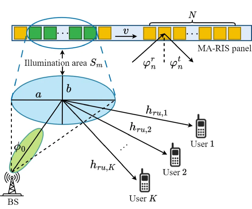
In a downlink scenario leveraging MA-RIS, we explore a system where User Equipments (UE) receive data via reflections from a RIS panel composed of movable antenna elements as shown in Fig. 1. The BS is positioned at , and equipped with FPAs transmitting signal towards MA-RIS. The position of the FPA at BS can be represented as , for . As for UEs, denoted by , each is equipped with a single FPA. The position of the UE is denoted as . The MA-RIS panel, featuring with a certain length, enables 1D and 2D alignment MA moving horizontally from the left panel edge to the right panel edge. The 1D and 2D structures are equipped with and MAs separately, where we let to make sure the 1D and 2D structured MA-RIS have the same number of antennas. The position of the MA-RIS center is denoted as . The position of the MA is represented by Cartesian coordinates for , where denotes the 3D region within which the MAs can move freely [10, 1].
Given the dominant LoS link with a signal path between both the BS to MA-RIS and MA-RIS to UE channels, the normalized wave vector of one single transmit path can be represented by , where and represent the Elevation of Departure (EoD) and Azimuth of Departure (AoD) from the BS to MA-RIS link, respectively. Therefore, following [11], the path difference relative to the reference point is denoted as . Accordingly, the Field-Response Vector (FRV) at the BS, considering the linear FPA array, is expressed as:
| (1) |
where is the carrier length. Considering the 2D plane deployment of MA-RIS [4], therefore, the FRV for the transmit path from the MA-RIS at position , is simplified to a scalar value in the context of LoS channel model [12], yielding:
| (2) |
where represents the Azimuth of Arrival (AoA) for each MA-RIS element. By stacking together the ’s of all transmit MA, we obtain the collective FRV, is given by
| (3) |
Similarly, by defining , the FRV of MA-RIS with representing the AoD from each MA-RIS element to UE link is
| (4) |
The single UE is equipped with a single FPA with representing the AoA to UE, and the corresponding FRV can be defined as
| (5) |
The channel vector for the BS-RIS link can then be written as
| (6) |
while the channel vector for the RIS-UE link can be written as
| (7) |
As in [13, 6], we denote and , and elements in those channel vectors are separately given as
| (8) |
| (9) |
where and represent the channel’s response. Therefore, the received signal at UE can be expressed as follows:
| (10) |
where is the received power, is the signal transmitted by the BS, is the additive complex Gaussian noise with zero mean and variance of , and is the phase shift matrix of MA-RIS. Letting , can be expanded as
where is the effective number of illuminated elements determined by the illumination area in MA-RIS, leading to the UE’s received instantaneous SNR of
| (12) |
By inspecting Eq. (12), we note that reaches its maximum value in correspondence of:
| (13) |
Hence, we can get the maximum SNR as , where , and the average SNR is .
II-B Topology of MA-RIS illumination area
Let us consider the system model shown in Fig. 1. All the elements are moving horizontally, with the same constant speed from the RIS’s left panel edge toward the right edge. By fitting the illumination area into an elliptic shape, we can derive the illumination area that affects the UE’s SNR. In order to capture the most important feature in the context of MA-RIS – the AoA and AoD information related with the movement of MA – we followed the cosine model in [14, 5], and for the element of MA-RIS, its radiation pattern for the incident beam from BS is described using cosine model which is given as , where the HPBW of the transmitted beam is denoted as , with the angular information , and with representing the azimuth AoA for MA-RIS center. The radiation pattern of the element of MA-RIS corresponding to the incident and reflect beam is separately defined in a similar way as in [14], as and with representing the azimuth AoD from MA-RIS element to UE. Therefore, we get the received power at the UE as
| (14) |
where is the transmit power, represents the size of a flat MA-RIS element, and denote the 3D distance between BS to MA-RIS element and the 3D distance between the MA-RIS element to UE, respectively.
We model the illumination area of the MA-RIS as an elliptical shape with area size as . The semi-major and semi-minor axes of the ellipse area are calculated as and where is the 3D distance between BS and the center of the MA-RIS panel, is the Elevation of Arrival (EoA) from BS to MA-RIS’s center. Therefore, we can get the effective illuminated number of the 1D and 2D MA-RIS as , , where is the inter-element spacing, represents the ceiling function.
II-C Outage Probability
We use the same method to evaluate the performance of outage probability as [5], defined as the probability that the SNR is smaller than a given threshold ,
| (15) |
where denotes the Cumulative Distribution Function (CDF) of , where , where we denote . With the method of moment matching [15], we can obtain , where is the incomplete Gamma function, while is the Gamma function.
III Performance Analysis
We analyse the performance in near field and assume that the elements within the MA-RIS configuration shift horizontally, transitioning from the panel’s left edge to its right edge. The positions of BS and UE are set as m and m, the carrier frequency is GHz, the noise variance is dBm. The RIS panel length is 1m, and the number of elements is . The antenna movement velocity is m/s, with the traversal time thus amounting to s .
A Transmit Power and Number of Elements : Effect on Outage probability
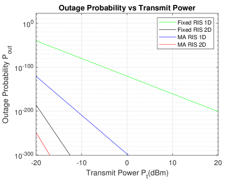
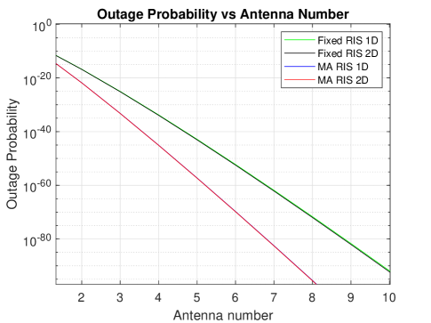
As shown in Fig.2LABEL:sub@OutvsPt, the outage probability decreases with an increase in transmit power for all configurations. In 2D scenario with 21 elements and -20 dBm transmit power, the MA-RIS achieves around 24% better performance than FPA-RIS in terms of outage probability. In a 2D scenario, the outage probability sharply decreases with increasing transmit power due to better control over signal propagation and interference mitigation. This is because the additional dimension allows for more precise optimization of signal paths, resulting in improved channel conditions. The impact of number of elements on outage probability is shown in Fig.2LABEL:sub@OutvsN, with the transmit power fixed at -20 dBm. Despite being limited by the single-path condition, there is no significant difference between the 1D and 2D configurations for both the MA-RIS and FPA-RIS settings. In particular, the results show that MA-RIS uses fewer elements than FPA-RIS to achieve the same level of performance, for example for an outage probability of , MA-RIS uses 25% fewer elements than FPA-RIS.
These promising results are the consequence of MA-enabled dynamic reconfiguration of antenna elements, allowing for adaptive adjustment of the antenna pattern and phase distribution. This flexibility can be leveraged to optimize the signal path and mitigate multipath fading, leading to enhanced communication reliability and lower outage probabilities compared to FPA-RIS, which have a limited capability to adapt to changing channel conditions.
B Effective Number of MA-RIS
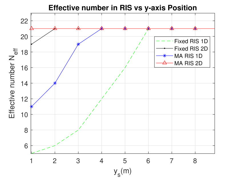
We set both the MA-RIS and FPA-RIS panels are depicted moving along the y-axis, denoted as in Fig.3. They traverse from an initial position of 1m to the maximum height of 15m in increments of 2 meters. In order to compare the performance of FPA-RIS and MA-RIS over the same overall panel length, the antenna spacing for FPA-RIS is , while the antenna spacing for MA-RIS is . We can observe that for both 1D and 2D configurations for the MA-RIS, the effective antenna number reaches its maximum value for lower values of as compared to FPA-RIS. This indicates that the ability to adjust the position of the RIS panel allows for optimizing the reflective path and thus the effective utilization of more antenna elements. We also notice that in 2D configurations, the RIS can quickly reach its maximum as it begins to move from the initial position along the y-axis. This implies that, the 2D RIS has a higher initial capacity for effective signal reflection due to its expanded interaction field, reaching peak performance with minimal movement. Instead, for 1D configurations, the effectiveness of the RIS in terms of increases more significantly as one moves to higher positions along the y-axis. In fact, in 1D setups the initial positions may not be optimal for capturing and redirecting signals effectively, while as the RIS moves to higher y-axis positions, it can encounter angles and positions where the linear array of antennas becomes more aligned with the direction of the incident signals, thereby increasing the effective number of antennas that can contribute to signal reflection.
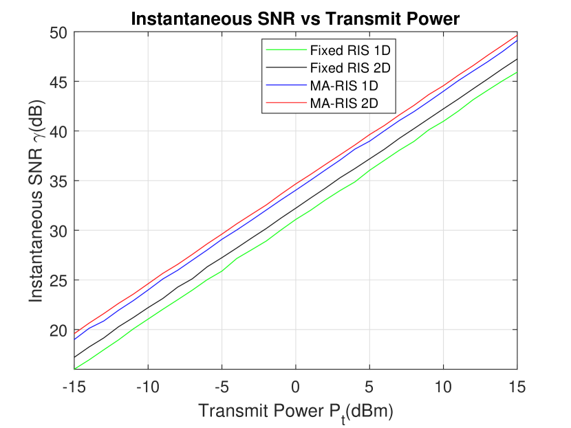
C Instantaneous SNR
In Fig.4, we compared instantaneous SNR versus the transmit power . We can see for example that when the transmit power is 0 dBm, then the MA-RIS’s instantaneous SNR is about 3 dBm and 2.5 dBm higher than FPA-RIS in 1D and 2D setups, respectively. This is due to the fact that MA-RIS systems have the inherent advantage of being able to adapt their position and orientation, in response to the environment and the direction of the incoming signal. This adaptability allows them to optimize the reflection path, enhancing the signal’s strength at the receiver and thereby improving the SNR. The performance of MA-RIS and FPA-RIS in both 1D and 2D configurations are nearly the same.
We can also observe that the 2D configurations offer superior performance compared to 1D configurations, this is due to the fact that the instantaneous SNR is determined by , 2D has higher geometric compactness than 1D which leads to the difference of SNR, with slight difference regardless with MA-RIS and FPA-RIS settings. 2D configurations allow for more sophisticated beamforming strategies, leveraging the additional dimension to focus the energy more precisely towards the receiver. Moreover, 2D RIS configurations can accommodate a wider range of AoA and AoD values for the signal. This capability enables them to maintain high SNR levels over a variety of transmission and reception scenarios, unlike 1D RIS, which is more limited in this respect.
In 1D configurations, the FPA-RIS and MA-RIS achieves nearly the same performance. This is due to the fact that the geometric compactness leads to the difference of and the 2D RIS can achieve the highest average SNR.
IV Conclusion
In this article, we derived the effective illumination area of MA-RIS systems. Our results show that the MA-RIS configuration generally provides a performance advantage over FPA-RIS, particularly in 2D setups. The consistently higher effective number of elements in 2D MA-RIS, the higher SNR, and the lower outage probability, all highlight the benefits of incorporating reflective element mobility into RIS design.
Our work highlights the importance of considering the following factors with regard to antenna elements: the element geometry distribution, i.e., 1D or 2D, and each element’s position in RIS panel, as well as the position of the RIS panel. Those factors are deeply connected with the angles of incidence and interaction with reflection signals, which contribute the signal strength and coverage. This could prove particularly beneficial in dynamic or large-scale environments, e.g., V2X and Massive MIMO communication systems, since the flexible adjustment of the antenna positions could provide an important additional degree of freedom to capture the geometry change, resulting in enhanced coverage, and improved signal quality. Despite our work highlight advantages of MA-RIS, the limitations inherent in our current model set the stage for our future efforts to refine and expand its capabilities. The model’s idealized assumptions, such as a fixed single-user position and a single-path condition, have resulted in a notably low outage probability. Our future work will aim to address these limitations by incorporating more realistic user scenarios and multiple path conditions, enhancing both the model’s applicability and accuracy.
References
- [1] L. Zhu, W. Ma, and R. Zhang, “Modeling and performance analysis for movable antenna enabled wireless communications,” arXiv preprint arXiv:2210.05325, 2022.
- [2] L. Zhu, W. Ma, Z. Xiao, and R. Zhang, “Performance Analysis and Optimization for Movable Antenna Aided Wideband Communications,” arXiv preprint arXiv:2401.08974, 2024.
- [3] X. Pi, L. Zhu, Z. Xiao, and R. Zhang, “Multiuser communications with movable-antenna base station via antenna position optimization,” arXiv preprint arXiv:2308.05546, 2023.
- [4] K. Ntontin, A.-A. A. Boulogeorgos, D. G. Selimis, F. I. Lazarakis, A. Alexiou, and S. Chatzinotas, “Reconfigurable intelligent surface optimal placement in millimeter-wave networks,” IEEE Open Journal of the Communications Society, vol. 2, pp. 704–718, 2021.
- [5] Z. Cui and S. Pollin, “Impact of Reconfigurable Intelligent Surface Geometry on Communication Performance,” IEEE Wireless Communications Letters, 2023.
- [6] G. Hu, Q. Wu, D. Xu, K. Xu, J. Si, Y. Cai, and N. Al-Dhahir, “Intelligent Reflecting Surface-Aided Wireless Communication with Movable Elements,” arXiv preprint arXiv:2311.02376, 2023.
- [7] H. Zhang, B. Di, Z. Han, H. V. Poor, and L. Song, “Reconfigurable intelligent surface assisted multi-user communications: How many reflective elements do we need?” IEEE wireless communications letters, vol. 10, no. 5, pp. 1098–1102, 2021.
- [8] S. Yang, W. Lyu, Z. Hu, Z. Zhang, and C. Yuen, “Channel estimation for near-field xl-ris-aided mmwave hybrid beamforming architectures,” IEEE Transactions on Vehicular Technology, 2023.
- [9] Y. Xin, Y. Xu, Q. Liu, C. Huang, D. Huang, and J. Zhou, “Robust and outage-constrained energy efficiency optimization in ris-assisted noma networks,” in 2022 IEEE 95th Vehicular Technology Conference:(VTC2022-Spring). IEEE, 2022, pp. 1–5.
- [10] Z. Cheng, N. Li, J. Zhu, X. She, C. Ouyang, and P. Chen, “Movable Antenna-Empowered AirComp,” arXiv preprint arXiv:2309.12596, 2023.
- [11] H. Qin, W. Chen, Z. Li, Q. Wu, N. Cheng, and F. Chen, “Antenna positioning and beamforming design for fluid antenna-assisted multi-user downlink communications,” IEEE Wireless Communications Letters, 2024.
- [12] W. Ma, L. Zhu, and R. Zhang, “MIMO capacity characterization for movable antenna systems,” IEEE Transactions on Wireless Communications, 2023.
- [13] Z. Cheng, N. Li, J. Zhu, X. She, C. Ouyang, and P. Chen, “Sum-rate maximization for movable antenna enabled multiuser communications,” arXiv preprint arXiv:2309.11135, 2023.
- [14] X. Yu, J. Zhang, M. Haenggi, and K. B. Letaief, “Coverage analysis for millimeter wave networks: The impact of directional antenna arrays,” IEEE Journal on Selected Areas in Communications, vol. 35, no. 7, pp. 1498–1512, 2017.
- [15] Z. Cui, K. Guan, J. Zhang, and Z. Zhong, “SNR coverage probability analysis of RIS-aided communication systems,” IEEE Transactions on Vehicular Technology, vol. 70, no. 4, pp. 3914–3919, 2021.