Dual-Port Grid-Forming Interconnecting Power Converters in Hybrid AC/DC Grids
Abstract
Interconnecting power converters (IPC) are the main elements enabling the interconnection of multiple high-voltage alternating current (HVAC) and high-voltage direct current (HVDC) subgrids. These converters can be classified either as grid-forming or grid-following. These roles can be assigned to both ac and dc terminals. This work compares state-of-the-art single-port grid-forming and grid-following control schemes with a dual-port grid-forming control scheme, which can simultaneously form a stable voltage on the ac and the dc sides. The dual-port grid-forming small-signal stability and dynamic behavior under fluctuations in the power flow are studied and compared against state-of-the-art control architectures. Moreover, the dual-port control scheme is validated and tested on a down-scaled laboratory platform with several transient events.
Index Terms:
power converters, grid-forming, grid-following, AC/DC, dual-port.April 2024
I Introduction
The energy transition is transforming the power system worldwide. The increasing need to integrate renewable energy sources into the grid is introducing new engineering solutions. The planned energy islands in the North Sea and the Baltic Sea [1] are one of the well-known examples. These projects will be able to deal with large offshore wind resources specific to these areas. Moreover, the exploitation of these natural resources will be shared among countries with several energy corridors. The key technology that makes this integration reliable is high voltage direct current (HVDC), which enables the transmission of electric energy across long distances [2]. These systems have already been deployed in several projects, usually in the form of point-to-point connections (except for China [3, 4, 5, 6]). The energy islands will use multi-terminal HVDC systems (MT-HVDC) [7]. In this case, the interconnecting power converters will form an MT-HVDC grid. This grid may also expand shortly if the existing electric corridors in the North Sea are interconnected. If these interconnections are built, the system will become a hybrid ac/dc system connecting different asynchronous ac grids with MT-HVDC systems. The most important elements enabling this integration are the interconnecting power converters (IPC). In this kind of system, the state-of-the-art technology is voltage source converters (VSCs), more specifically, the modular multilevel converter (MMC) [8].
When planning and operating these systems several challenges can arise. In general, to ensure the proper operation of the electric system, different constraints need to be fulfilled [9]. Principally, it is needed to ensure small-signal stability, good dynamic performance, and robustness against transient events. These converters must be properly designed in a system consisting of several IPCs. One of the key points is the control of these converters. Plenty of different proposals can be found already in the literature [10, 11, 12, 13, 14]. These can be categorized between grid-following and grid-forming, both on the ac and dc sides [15]. The most common architectures are ac grid-following and dc grid-following, ac grid-forming and dc grid-following, and ac grid-following and dc grid-forming. Recently, in [15], an ac grid-forming and dc grid-forming (dual-port) architecture was proposed. This will be analyzed at the core of this paper.
All these control approaches can be interconnected together in the same system. Therefore, the combinations of these control laws need to fulfill small-signal stability, good dynamic performance, and ensure transient stability. The small-signal stability was studied in [16], where the spatial distribution of these control laws affects the stability of the system when different power flow scenarios are considered. The dynamics of the system are also a very important feature to consider. Some restrictions exist; for example, all these combinations must ensure a good rate of change of frequency (RoCoF) and frequency nadir on the ac side [17, 18]. On the dc side, the dc voltage overshoot is also important, between other aspects [17]. These systems are also disturbed by transients, such as the loss of some synchronous generators. Moreover, some faults can also occur in the system. In this sense, one of the measures applied to limit the spread of these contingencies is the intentional islanding [18, 19], which can be carried out both on the ac and the dc sides in MT-HVDC schemes. Therefore, control architectures that can operate in weak grid conditions and islanding mode are becoming popular.
One of the control algorithms that can fulfill all these requirements is the dual-port control. The contributions of this paper are related to this control approach,
-
1.
The small-signal stability of the dual-port control scheme is analyzed under various power flow conditions, and the stability margins are compared to that of the state-of-the-art control architectures.
-
2.
The dynamics response of the dual-port control scheme is compared against that of the state-of-the-art control architectures.
-
3.
The dual-port control architecture is validated against transient events in a down-scaled laboratory platform. Moreover, its behavior is compared with state-of-the-art control architectures.
II Interconnecting Power Converters Roles
The role played by an IPC in the system depends on its governing control law. In general, on the ac terminal, two different roles can be applied, which are grid-forming (GFM) and grid-following (GFL). The proper definition of these roles is still under debate in the industry and the research community. Some specific characteristics that need to fulfill these schemes are defined in [18]. It is not within the scope of this paper to define these roles. However, as this classification is important in this work, some common ground is defined to characterize them.
The AC-GFL roles interchange active and reactive power while aligned with the grid usually using a phase-locked-loop (PLL) [20]. Several control schemes found in the literature can be classified in this group [21, 22, 23, 24]. An example of this is depicted in Fig. 1. When , the active and reactive power interchanged with the ac grid is fixed through an outer loop behind a current control. The IPC is aligned with the ac grid using a PLL.
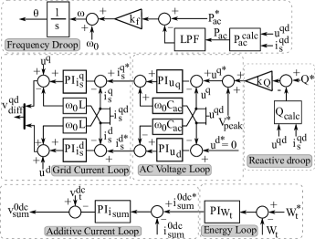
The AC-GFM roles interchange active and reactive power while it can form a stable ac grid at the ac terminal. Numerous control schemes documented in the literature fall under this category [25, 26, 27, 28, 29]. An example is depicted in Fig. 2. This control regulates the ac voltage using an outer ac voltage loop behind an ac current loop. The voltage phase angle is regulated by a power-frequency droop.
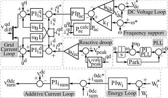
While these roles are generally well-defined for the ac side, these are less standardized for the dc terminals [30]. However, in MT-HVDC grids of the future, assigning such roles on the dc-side needs to be also considered. A first attempt was made in [30], where a general comparison between dc voltage droop schemes and AC-GFL and AC-GFM schemes is presented. If the dc voltage droop scheme is enabled in Fig. 1 (), the converter is regulating the dc voltage. This is achieved by regulating the ac power injected by the converter, causing a shift in the internal energy, which is subsequently readjusted from the dc side. A priori, this scheme could be labeled as a DC-GFM scheme.
II-A Dual-Port approach
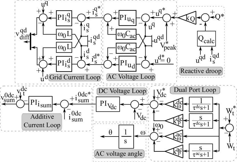
The literature on both AC-GFM and DC-GFM controlled IPCs is scarce. This paper attempts to fill this gap by focusing on the control law proposed in [15]. The control scheme is depicted in Fig. 3. The main idea behind this control scheme is to form the ac and dc voltage while controlling the internal energy () through the ac and dc sides. The core of the control is highlighted in Fig. 3 as ”Dual Port Loop”. It consists of droops and derivative droops for the - and - relation. The droop functions stabilize the internal energy while the derivative droop functions provide additional damping.
Notice that in the case where an AC-GFL scheme (Fig. 1) is implemented, a stable ac grid is needed as these control laws are not stable when there is no other element forming the ac grid. The same happens with the DC-GFL approach (scheme in Fig. 1 with ), where a stable dc grid is required. The dual-port’s key advantage, compared to other control schemes (Fig. 1 and Fig. 2) is its stability in the absence of elements forming both ac and dc grids [15].
III Small-Signal Stability comparison between state-of-the-art control roles and dual-port
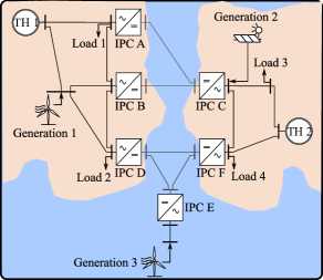
When considering the small-signal stability of a system as the one depicted in Fig. 4 different factors need to be considered. As studied in [16] the stability of the system is subjected to the converter control role configurations (CCRC), i.e., how the different control laws are spatially distributed, and also on the power flow [16]. In this first analysis, the stability of the dual-port approach is compared with the state-of-the-art converter control laws. The small-signal stability of the case study presented in Fig. 4, with the parameters summarized in Appendix -A, is evaluated for the different possible converter control role configurations using the state-of-the-art control laws of Fig. 1 and Fig. 2 and one where the dual-port approach is used in all the IPCs.
In Fig. 5 the stability of the CCRC without dual-port and one with all the IPCs in dual-port is evaluated against 100 randomly generated power flows. The power flows are generated similarly to [16]. As seen in the figure, the dual-port approach is stable for all the power flow scenarios. On the other hand, the CCRC with state-of-the-art control laws, are not all of them stable for all the power flows.

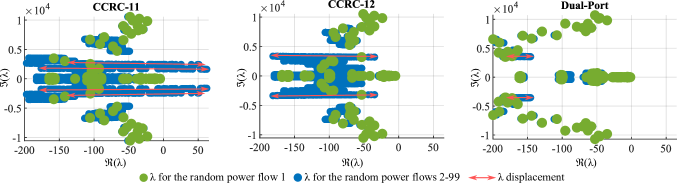
Next, the eigenvalues sensitivity of the system depicted in Fig. 4 is compared for two CCRCs that use state-of-the-art control laws (CCRC-11 and CCRC-12) and the one that only uses dual-port controls. The spatial distribution among the control laws for CCRC-11 and CCRC-12 is defined in Tab. I.
| IPC-A | IPC-B | IPC-C | |
| CCRC-11 | AC-GFM | AC-GFL (0) | AC-GFL (0) |
| CCRC-12 | AC-GFM | AC-GFL (0) | AC-GFL (0) |
| IPC-D | IPC-E | IPC-F | |
| CCRC-11 | AC-GFM | AC-GFL (0) | AC-GFM |
| CCRC-12 | AC-GFL (0) | AC-GFM | AC-GFM |
As seen in Fig. 6, CCRC-11 is unstable for some of the power flows whereas CCRC-12 and the dual-port approach are stable for all power flows. The important difference between these configurations relies on the displacement that the eigenvalues () present. In the case of CCRC-11, the eigenvalues present a high mobility when changing the power flow. The displacement of the eigenvalues when CCRC-12 is used is lower compared with CCRC-11. A very different scenario is observed in the eigenvalues behaviour when the dual-port approach is deployed in all the IPCs. As it is seen in Fig. 6 the eigenvalues are almost static. The dual-port approach minimizes the sensitivity that the system has against the power flow variation.
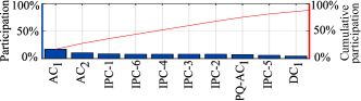
As a result of this first analysis, the dual-port approach seems very robust against the power flow fluctuation. Therefore, this control approach is seen as a very good alternative to conventional control laws in terms of small-signal stability. With the other control laws, the causes of instability are diverse and this makes it difficult to find suitable combinations and control parameters which can be robust against the power flow fluctuation. In Fig. 7 a Pareto chart is shown with the causes of the instability of the unstable CCRCs, extracted from the participation factors of the unstable eigenvalues. As seen in the figure, there is no clear factor that can be improved to enhance the stability of these combinations.
III-A Dynamic interactions between ac and dc sides
This section focuses on the possible dynamic interactions that might occur on the ac and dc converter sides. To study this, the IPC admittance matrix is calculated.
The ac side IPC’s admittance matrix () can be calculated as
| (1) |
The dc side IPC’s admittance matrix () can be calculated as
| (2) |
Studying only the ac and dc side admittances ( and ) is not enough, as it ignores the fundamental fact that ac and dc dynamics are impacted by one another. Thus, hybrid ac-dc admittances need to be considered where the cross-coupling between the ac and dc sides are captured by the and (mapping ac dynamics to the dc-side), and the and (relating to the dc-side dynamics affecting ac-side dynamics) [31, 32]. It can be calculated as,
| (3) |
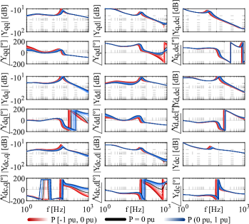
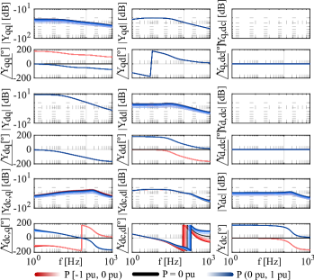
The hybrid admittance for the dual-port approach is depicted in Fig. 8. As it is shown, the dual-port approach couples both ac and dc sides. It exchanges energy from the dc to the ac side through the admittances and . On the other side, it interchanges energy from the ac to the dc side through the admittances and . Therefore, both ac and dc sides are coupled. It is important to notice that the admittance of the IPC using this control does almost not change when the converter operates in different operating points.
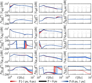
Next, the admittances of the state-of-the-art control approaches are studied and compared with the dual-port. The admittance of an IPC with AC-GFM control law (Fig. 2) is depicted in Fig. 9. As it is shown, in this case, the dc side is not coupled with the ac side as and are zero. Therefore, the perturbations seen on the dc side do not cross to the ac side. It acts as a firewall from the dc to the ac side, i.e., the dynamics of the ac-side are decoupled from the dc-side. This is an important difference between the dual-port and the AC-GFM state-of-the-art control law. Moreover, looking at it can be observed that this control law acts as a positive resistance (º for (0,2100)) when the power is negative (it is absorbing power from the dc side). However, when the power is positive (it is injecting power to the dc side) the converter acts as a negative resistance (º for (0,2100)). In the case of the dual-port, it acts almost always as a positive resistance ( for (0,21000)).
The admittance of an IPC with AC-GFL control law and 0 (Fig. 1) is depicted in Fig. 10. As it is shown, in this case, the ac and dc sides are coupled as and are not zero. Therefore, it has a similar behavior as the dual-port where the perturbations from both the ac and dc sides can cross to the other side. Moreover, looking at it can be observed that this control law acts as a positive resistance (º for (0,21000)) when the power is positive (it is absorbing power from the ac side). However, when the power is negative (it is injecting power from the ac side) the converter acts as a negative resistance (º for (0,2100)). In the case of the dual-port, the converter acts almost always as a positive resistance ( for (0,2100)). This is also an important difference with the dual-port.
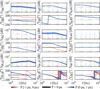
Finally, the admittance of an IPC with AC-GFL control law and 0 (Fig. 1) is depicted in Fig. 11. In this case, the behavior seen from the ac side is similar to the one with the control AC-GFL and 0 (,,,, and ), whereas from the dc side is similar to the AC-GFM control (, and ).
III-B Passivity analysis
To understand better the dual-port’s robustness against variations in the power flow, a passivity analysis [33, 34, 35, 36] is performed. The passivity of the control roles is evaluated from the ac and the dc side and uses the hybrid admittance to study the IPC’s complete passivity [37].
The ac passivity of the IPC can be calculated with . The IPC is passive from the ac side if the minimum eigenvalue of is positive [36]. The passivity from the dc side can be calculated with , Analogously, the IPC is passive from the dc side if the minimum eigenvalue of is positive (H indicates the Hermitian conjugate).
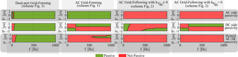
Analyzing the IPC passivity only from the ac and dc sides might lead to incorrect conclusions. Therefore, the complete IPC passivity can be analyzed with . The IPC is passive, including the ac/dc coupling terms, if the minimum eigenvalue () of is positive. The passivity analysis is depicted in Fig. 12. It is calculated with the parameters summarized in Appendix -A. The frequency range is focused on 0 Hz to 1 kHz as the intention is to compare the dynamics of the outer loops [38].
As shown in Fig. 12, the dual-port approach is the control role scheme which has a smaller area where the converter is not passive. Seen from the ac side, the dual-port is passive except for a small range. Similar results are obtained when it is evaluated from the dc side. When evaluating the hybrid ac/dc passivity it can be seen that the IPC with dual-port is passive for frequencies higher than 100 Hz. This depends on the operation point as shown in Fig. 12. When injecting active power to the ac side, the passivity is achieved at lower frequencies.
The AC-GFM scheme is almost passive, as seen from the ac side. However, when it is seen from the dc side, it is not passive, especially when the converter is injecting active power to the ac side (P0). When considering the ac/dc cross terms the converter is almost not passive except for a small range at high frequencies. Therefore, it is close to the passivity area where the damping could be enough to prevent instabilities. The other two schemes are not passive when seen from the ac side. From the dc side, the passivity is more dependent on the operation point. When the ac/dc cross terms are considered, both control laws are entirely not passive.
As deduced from the passivity analysis, the dual-port scheme is less prone to induce stability problems in both the ac and the dc sides.
IV Dynamic Performance comparison between state-of-the-art control roles and dual-port
In this section, the dynamic performance of the combinations that are stable in all the power flow scenarios and the dual-port approach are compared. Two case studies are considered. The first one is the loss of the generation unit that contributes more in ac grid 1 and the second one is the loss of the generation unit that contributes more in ac grid 2. In Fig. 13 the responses of the different configurations against these disturbances are shown. The power flow used is summarized in Appendix -A.
From the 16 converter control role combinations that were stable for all the power flow scenarios considered in Section III, only 5 of them can withstand both perturbations. On the other hand, the configuration where all the IPCs use the dual-port approach can withstand both perturbations (see Fig. 13).
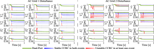
In a given way, the dual-port achieves such good results because it uses its internal energy to damp all these perturbations. As it is seen in Fig. 13 the internal energy of the dual-port is deviated from the nominal value when these perturbations occur. In this sense, it is very important to properly tune the control variables and in a way that the maximum energy deviation does not exceed a certain limit where the converter is no longer able to properly modulate. As discussed in [15] the internal energy can be readjusted to the nominal value after the contingency. Another important consideration is that the dual-port spreads over to all the system the contingencies. A perturbation in one ac subsystem is reflected in all others. On the other hand, some CCRCs with state-of-the-art control roles can isolate perturbations within the disturbed ac system, as discussed in Section III.
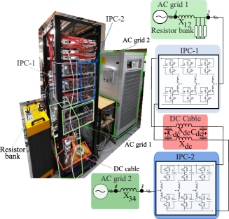
V Transient and islanded mode stability in a down-scaled laboratory platform
The different control laws have been implemented in a down-scaled point-to-point link based on an Imperix Platform. The scheme implemented is depicted in Fig. 14. The parameters used in the down-scaled platform are summarized in Appendix -B.
In this case, at least 5 different converter control role configurations are possible (see Tab. II).
| IPC-1 | IPC-2 | |
| CCRC-1 | AC-GFL (Fig. 1 ) | AC-GFL (Fig. 1 ) |
| CCRC-2 | AC-GFL (Fig. 1 ) | AC-GFL (Fig. 1 ) |
| CCRC-3 | AC-GFM (Fig. 2) | AC-GFL (Fig. 1 ) |
| CCRC-4 | AC-GFL (Fig. 1 ) | AC-GFM (Fig. 2) |
| CCRC-5 | Dual-Port (Fig. 3) | Dual-Port (Fig. 3) |
Next, these CCRCs are compared against the dual-port approach for different case studies.
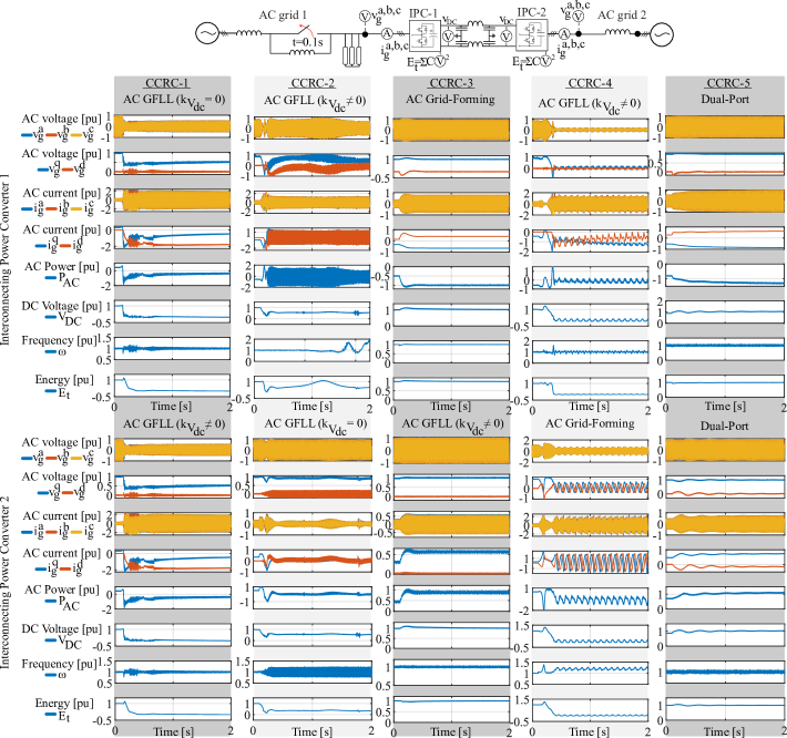
V-A Weak grid
In the first case study, the system is tested for a weak grid in AC-1. At time t=0.1 s, the inductance on AC-1 is changed, making the system weaker (SCR from 5.5 to 2.75). In Fig. 15, the response of the different configurations to this perturbation is shown. Only two configurations can withstand the operation on a weak grid. These are CCRC-3 and CCRC-5. The first one corresponds to the configuration where the IPC-1 is in AC-GFM mode, whereas the second one implements both converters in dual-port. It is well reported in the literature that AC-GFM schemes can support the operation in weak grids [39, 40, 41]. But, as a conclusion of these results, it can also be stated that the dual-port approach is another control role that can operate in weak grid conditions. Note that as the system is symmetric, similar results would happen if the weak grid is applied in ac grid 2. However, in this scenario, the configurations that would survive the transient would be CCRC-4 and CCRC-5, which mirror the previous combinations. Note that the configuration that uses dual-port will be the only one that could operate with weak grids in both ac grids as all the other configurations need at least one IPC which implements a GFL scheme (Fig. 1 with 0) to control the dc voltage. This controller has been proven to be unable to operate in weak grids, as seen in Fig. 15.
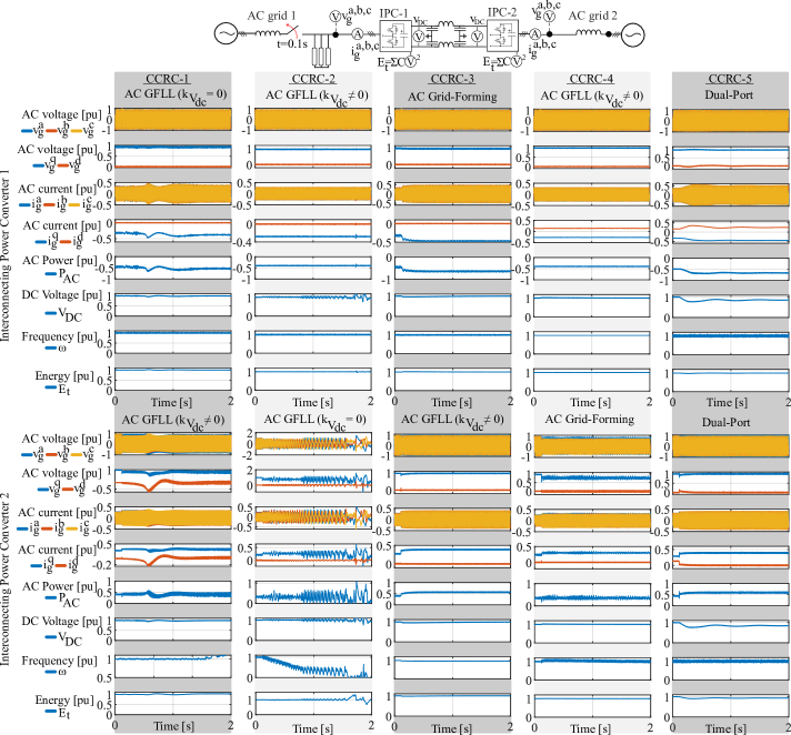
V-B Islanded ac
In this second case study, the system is tested against islanding in AC-1. That is, at time s, the breaker in ac grid 1 is activated. Therefore, IPC-1 is directly connected to the resistive load, and no other element forms the grid. In Fig. 16, the response of the different configurations to this perturbation is shown. Of the five configurations, only two can withstand the operation in ac islanding mode in grid 1. These are CCRC-3 and CCRC-5. The first one corresponds to the configuration where the IPC-1 is in the AC-GFM role. The second one is the case where both IPCs are in dual-port. The CCRC-4 seems to be almost stable, at least from the IPC-1. It has to be noted that on the ac side, there is only a resistive load that provides extra damping on the ac side. If some capacitors or inductances were added, this could lead to instability. Moreover, some oscillations appear in IPC-2, which is in AC-GFM. This is because the power that IPC-1 can interchange with ac side 1 is limited to the ac voltage given by the resistance previous to the transient. After all, IPC-1 only regulates the dc voltage (it does not accommodate the ac voltage nor the ac frequency to newer conditions). Therefore, this configuration can also be discarded to operate in ac islanding in ac grid 1. In summary, only configurations where the AC-GFM role is implemented in ac side 1 can operate in islanding mode. Similar to the previous case study, this can also be seen as a symmetric system if the resistance was placed on both ac sides. Again, it is widely reported in the literature that the AC-GFM role can operate in islanding mode [39, 40, 41]. However, as a conclusion of these results, it can also be stated that the dual-port approach is another control role that can operate in ac islanding conditions.
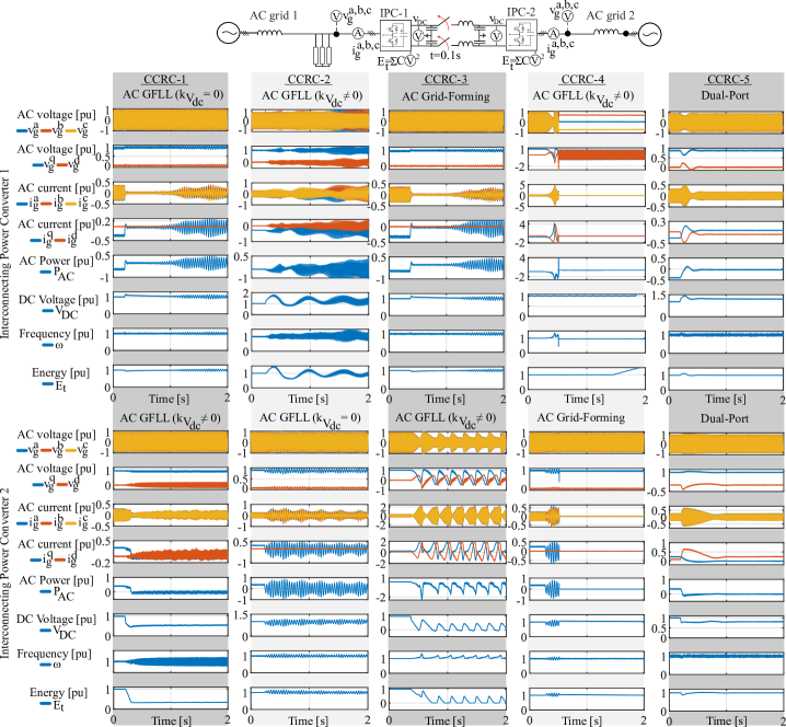
V-C Islanded dc
In this last case study, the system is tested when the dc link is lost, i.e., the breaker in the dc line is opened at time t=0.1 s. At that time, both IPCs do not have a stable dc grid to be connected with, i.e., there is no element forming the dc grid. In Fig. 17, the response of the different configurations to this perturbation is shown. Of the five configurations, only one of them is stable after the disturbance. This is CCRC-5, which corresponds to the dual-port configuration. All the others are unstable. This is because the only configuration with DC-GFM capability at both sides of the dc link is the dual-port one. Only the IPC with 0 could still be operational on the other configurations. However, as the perturbation is very severe in the other IPC terminal, all of them lose the other terminal as well. This is one of the main advantages of having a dual-port scheme in both IPCs because it can withstand this kind of outage. This can be especially interesting in MT-HVDC systems where some HVDC lines can be lost, but the system can still operate if configured with dual-port. Another scenario can consider dc loads. In this case, these loads could also be fed by the IPCs.
VI Conclusions
This article analyzes the dual-port approach, which is a control law that achieves GFM on both the ac and dc sides. The dual-port control law is compared with state-of-the-art control laws in small-signal stability, dynamic behavior, and transient stability. It is revealed that dual-port control is more robust than state-of-the-art control laws regarding small-signal stability when the power flow is changed. The dual-port is also able to achieve good dynamics and stability when dealing with large transients in the grid such as the loss of generation units. Finally, the dual-port approach is validated in a down-scaled platform where this control law is compared with the state-of-the-art control laws. It has been demonstrated that the dual-port control can deal with weak grids and islanding operations on both the ac and dc sides.
References
- [1] “Energy islands in denmark,” https://en.energinet.dk/infrastructure-projects/energy-islands/, [16-01-2024].
- [2] D. V. Hertem, O. Gomis-Bellmunt, and J. Liang, HVDC grids for offshore and supergrid of the future. Hoboken, NJ, USA: Wiley, 2016.
- [3] X. Li, Z. Yuan, J. Fu, Y. Wang, T. Liu, and Z. Zhu, “Nanao multi-terminal VSC-HVDC project for integrating large-scale wind generation,” in IEEE PES General Meeting, 2014.
- [4] Y. Pipelzadeh, B. Chaudhuri, T. Green, Y. Wu, H. Pang, and J. Cao, “Modelling and dynamic operation of the zhoushan dc grid: Worlds first five-terminal vsc-hvdc project,” in International High Voltage Direct Current Conference, 10 2015.
- [5] H. Pang and X. Wei, “Research on key technology and equipment for zhangbei 500kv dc grid,” in International Power Electronics Conference), 2018, pp. 2343–2351.
- [6] “NR’s VSC-HVDC Solution, ±500kV Zhangbei DC grid for boosting large scale hybrid renewables penetration,” Tech. Rep., 2019.
- [7] T. Vrana, R. Torres-Olguin, B. Liu, and T. Haileselassie, “The north sea super grid - a technical perspective,” in 9th IET International Conference on AC and DC Power Transmission, 2010.
- [8] K. Sharifabadi, L. Harnefors, H.-P. Nee, S. Norrga, and R. Teodorescu, Design, Control and Application of Modular Multilevel Converters for HVDC Transmission Systems. United States: Wiley-IEEE press, 2016.
- [9] O. Gomis-Bellmunt, E. Sánchez-Sánchez, J. Arévalo-Soler, and E. Prieto-Araujo, “Principles of operation of grids of dc and ac subgrids interconnected by power converters,” IEEE Transactions on Power Delivery, vol. 36, no. 2, 2021.
- [10] G. Bergna Diaz, J. Suul, and S. D’Arco, “State-space modelling of mmc for constant variables in steady-state,” 2016.
- [11] L. Harnefors, A. Antonopoulos, S. Norrga, L. Angquist, and H. Nee, “Dynamic analysis of modular multilevel converters,” IEEE Transactions on Industrial Electronics, vol. 60, no. 7, 2013.
- [12] L. Angquist, A. Antonopoulos, D. Siemaszko, K. Ilves, M. Vasiladiotis, and H. Nee, “Open-loop control of modular multilevel converters using estimation of stored energy,” IEEE Trans. Ind. Appl., 2011.
- [13] A. Antonopoulos, L. Angquist, and H. Nee, “On dynamics and voltage control of the modular multilevel converter,” in European Conference on Power Electronics and Applications, 2009.
- [14] D. Ma, W. Chen, L. Shu, X. Qu, and C. Hu, “A mmc-based multiport ac-n-dc converter for hybrid ac/dc systems,” IEEE Trans. Circuits Syst. II, Exp. Briefs, 2021.
- [15] D. Groß, E. Sánchez-Sánchez, E. Prieto-Araujo, and O. Gomis-Bellmunt, “Dual-port grid-forming control of mmcs and its applications to grids of grids,” IEEE Trans. Power Del., 2022.
- [16] J. Arévalo Soler, D. Groß, E. P. Araujo, and O. G. Bellmunt, “Interconnecting power converter control role assignment in grids with multiple ac and dc subgrids,” IEEE Transactions on Power Delivery, vol. 38, no. 3, pp. 2058–2071, 2023.
- [17] “High penetration of power electronic interfaced power sources and the potential contribution of grid forming converters,” ENTSO-E, Tech. Rep., 2020.
- [18] “Grid-forming capabilities: Ensuring system stability with a high share of renewables,” ENTSO-E, Tech. Rep., 2021.
- [19] “Reglamento 2016/631 de la comisión de 14 de abril de 2016 que establece un código de red sobre requisitos de conexión de generadores.”
- [20] Se-Kyo Chung, “A phase tracking system for three phase utility interface inverters,” IEEE Trans. Power Electron., vol. 15, no. 3, 2000.
- [21] E. Sánchez-Sánchez, E. Prieto-Araujo, A. Junyent-Ferré, and O. Gomis-Bellmunt, “Analysis of mmc energy-based control structures for vsc-hvdc links,” IEEE J. Emerg. Sel. Top. Power Electron., 2018.
- [22] A. G. Endegnanew, G. Bergna-Diaz, and K. Uhlen, “Avoiding ac/dc grid interaction in mmc based mtdc systems,” in EVER, 2017.
- [23] G. Bergna, J. A. Suul, and S. D’Arco, “Impact on small-signal dynamics of using circulating currents instead of ac-currents to control the dc voltage in mmc hvdc terminals,” in ECCE, 2016.
- [24] E. Prieto-Araujo, A. Junyent-Ferré, C. Collados-Rodríguez, G. Clariana-Colet, and O. Gomis-Bellmunt, “Control design of modular multilevel converters in normal and ac fault conditions for hvdc grids,” Electr. Power Syst. Res., vol. 152, 2017.
- [25] H. Saad, S. Dennetière, and P. Rault, “Ac fault dynamic studies of islanded grid including hvdc links operating in vf-control,” in IET International Conference on AC and DC Power Transmission, 2019.
- [26] L. Zhang, L. Harnefors, and H.-P. Nee, “Modeling and control of vsc-hvdc links connected to island systems,” IEEE Transactions on Power Systems, vol. 26, no. 2, 2011.
- [27] G. Denis, T. Prevost, P. Panciatici, X. Kestelyn, F. Colas, and X. Guillaud, “Review on potential strategies for transmission grid operations based on power electronics interfaced voltage sources,” in IEEE Power Energy Society General Meeting, 2015.
- [28] M. C. Chandorkar, D. M. Divan, and R. Adapa, “Control of parallel connected inverters in standalone ac supply systems,” IEEE Transactions on Industry Applications, vol. 29, no. 1, 1993.
- [29] J. M. Guerrero, L. Hang, and J. Uceda, “Control of distributed uninterruptible power supply systems,” IEEE Transactions on Industrial Electronics, vol. 55, no. 8, 2008.
- [30] K. Shinoda, M. Elsodany, J.-C. Gonzalez, J. Dai, A. Benchaib, and S. Bacha, “Comparison between dc voltage droop schemes and grid-following and grid-forming control in ac systems in view of interoperability of mtdc grids,” in European Conference on Power Electronics and Applications, 2023.
- [31] K. Ji, H. Pang, J. Yang, and G. Tang, “Dc side harmonic resonance analysis of mmc-hvdc considering wind farm integration,” IEEE Transactions on Power Delivery, vol. 36, no. 1, 2021.
- [32] K. Ji, G. Tang, H. Pang, and J. Yang, “Impedance modeling and analysis of mmc-hvdc for offshore wind farm integration,” IEEE Transactions on Power Delivery, vol. 35, no. 3, 2020.
- [33] L. Harnefors, X. Wang, A. G. Yepes, and F. Blaabjerg, “Passivity-based stability assessment of grid-connected vscs—an overview,” IEEE J. Emerg. Sel. Top. Power Electron., vol. 4, no. 1, 2016.
- [34] H. Saad, J. Mahseredjian, S. Dennetière, and S. Nguefeu, “Interactions studies of hvdc–mmc link embedded in an ac grid,” Electric Power Systems Research, vol. 138, 2016, special Issue: Papers from the 11th International Conference on Power Systems Transients.
- [35] F. Zhu, M. Xia, and P. J. Antsaklis, “Passivity analysis and passivation of feedback systems using passivity indices,” in 2014 American Control Conference, 2014.
- [36] M. Beza and M. Bongiorno, “Identification of resonance interactions in offshore-wind farms connected to the main grid by mmc-based hvdc system,” IJEPES, vol. 111, 2019.
- [37] D. Wang and K. Zhang, “Small-signal stability analysis of mmc-hvdc system based on hybrid passivity,” IEEE Transactions on Power Delivery, 2023.
- [38] N. Hatziargyriou, J. Milanović, C. Rahmann, V. Ajjarapu, C. Canizares, I. Erlich, D. Hill, I. Hiskens, I. Kamwa, B. Pal, P. Pourbeik, J. Sanchez-Gasca, A. Stankovic, T. Van Cutsem, V. Vittal, and C. Vournas, “Stability definitions and characterization of dynamic behavior in systems with high penetration of power electronic interfaced technologies,” Power System Dynamic Performance Committee (PSDP), Tech. Rep., 2020.
- [39] D. Groß, M. Colombino, J.-S. Brouillon, and F. Dörfler, “The effect of transmission-line dynamics on grid-forming dispatchable virtual oscillator control,” IEEE Transactions on Control of Network Systems, vol. 6, no. 3, 2019.
- [40] P. Vorobev, P.-H. Huang, M. Al Hosani, J. L. Kirtley, and K. Turitsyn, “A framework for development of universal rules for microgrids stability and control,” in IEEE Annual Conference on Decision and Control, 2017.
- [41] I. Subotić, D. Groß, M. Colombino, and F. Dörfler, “A lyapunov framework for nested dynamical systems on multiple time scales with application to converter-based power systems,” IEEE Transactions on Automatic Control, vol. 66, no. 12, 2021.
- [42] E. Sánchez-Sánchez, D. Groß, E. Prieto-Araujo, F. Dörfler, and O. Gomis-Bellmunt, “Optimal multivariable mmc energy-based control for dc voltage regulation in hvdc applications,” IEEE Transactions on Power Delivery, vol. 35, no. 2, 2020.
- [43] E. Sánchez-Sánchez, E. Prieto-Araujo, and O. Gomis-Bellmunt, “The role of the internal energy in mmcs operating in grid-forming mode,” IEEE J. Emerg. Sel. Top. Power Electron., vol. 8, no. 2, 2020.
- [44] L. Wang, Modelling and Control of Sustainable Power Systems, 2012.
-A Parameters used in Sections III-IV
Table III lists the parameters used for the IPC controls. The following tunning is used:
-
1.
Total energy control is designed to fix a maximum total energy fluctuation of 10% [42].
-
2.
AC power loop: achieve a first-order closed-loop response with = 10 ms.
-
3.
AC voltage loop: extracted from [43].
- 4.
-
5.
Current loops: Internal Model Control to achieve a closed-loop system with = 1 ms [44].
| Controller | [pu] | [pu] |
| Total energy loop | 0.019 | 0.48 |
| AC power loop | 0.38 | 177.5 |
| AC voltage loop | 67.89 | 271.58 |
| PLL | 1.24 | 200 |
| AC grid current loop | 0.54 | 8.65 |
| Inner current loop | 0.73 | 11.54 |
The parameters used specifically for the dual-port control laws are listed in Table IV.
| Parameter | Value | Units |
| 1 | pu | |
| 0.496 | pu | |
| 0.0031 | pu |
| Parameter | Value | Units |
| 0.0191 | pu | |
| 1 | ms | |
| 1 | ms |
| Element | P [MW] | Q [MVar] |
| Gen. 1 | 150 | 0 |
| Gen. 2 | 100 | 0 |
| Gen. 3 | 300 | 0 |
| Load 1 | -150 | -49.5 |
| Load 2 | -100 | -10 |
| Load 3 | -100 | -10 |
| Load 4 | -150 | 0 |
| Element | P [MW] | Q [MVar] |
| SG 1 | 338 | 0 |
| SG 2 | -342 | 0 |
| IPC A | -118 | 34 |
| IPC B | -238 | -0.5 |
| IPC C | 350 | -76 |
| IPC D | 126 | -59 |
| IPC E | -300 | -86 |
| IPC F | 168 | 27 |
-B Parameters used in the lab-scaled platform
The parameters used in the lab-scaled platform are listed in Table VI.
| Parameter | Value | Units |
| 50 | W | |
| 14.7 | V | |
| 0.18 | pu | |
| 0.18 | pu |
| Parameter | Value | Units |
| IPC-1 arm inductance | 0.18 | pu |
| IPC-2 arm inductance | 0.18 | pu |
| 0.18 | pu | |
| 1 | mF |
The general control parameters used in the IPCs for the lab-scaled platform are listed in Table VII.
| Controller | Proportional | Integral | Units |
| Grid Current Loop | 1.16 | 6.94 | pu |
| Additive Current Loop | 11.57 | 277.66 | pu |
| Total Energy Loop | 3.82 | 99.29 | pu |
| Active Power Loop | 0.02 | 254.61 | pu |
| AC Voltage Loop | 2.99 | 37.43 | pu |
| Frequency Droop | 0.0016 | - | pu |
| DC Voltage Loop | 0.04 | - | pu |
| Reactive Droop | 0 | - | pu |
The control parameters specifically used for the dual-port control law in the lab-scaled platform are listed in Table VIII.
| Parameter | Value | Units |
| 0.6981 | pu | |
| 0.04 | pu | |
| 0.0233 | pu |
| Parameter | Value | Units |
| 0.0004 | pu | |
| 1 | ms | |
| 1 | ms |