capbtabboxtable[][\FBwidth] \floatsetup[table]capposition=top
Extending Cislunar Communication Network Reach Using Reconfigurable Intelligent Surfaces
Abstract
This study introduces a novel approach to enhance communication networks in the cislunar space by leveraging Reconfigurable Intelligent Surfaces (RIS). Using the ability of RIS to dynamically control electromagnetic waves, this paper tackles the challenges of signal attenuation, directivity, and divergence in cislunar missions, primarily caused by immense distances and that Earth-based station transmitters do not always face the Moon. A new optimization problem is formulated, whose objective is to maximize the received signal-to-noise ratio (SNR) for Earth-to-Moon communications. We derive a closed-form solution to the problem of determining the optimal RIS phase shift configuration based on the effective area of the RIS. Through extensive simulations, this paper demonstrates how optimal adjustments in RIS phase shifts can significantly enhance signal integrity, hinting at the substantial potential of RIS technology to revolutionize long-distance cislunar communication.
Index Terms:
Cislunar communications networks, maximizing reaching distance, reconfigurable intelligent surface.I Introduction
In the quest to push the boundaries of human exploration, lunar missions stand as a testament to our technological ambition and prowess. These ventures into the vastness of space are not without significant challenges, chief among them the imperative of establishing robust communication links. These systems serve as the lifeline between the distant reaches of our solar system and Earth, facilitating the transmission of critical data and commands essential for the success and safety of such missions [1].
The importance of communication in these endeavors cannot be overstated, particularly as we confront the need to maximize the signal-to-noise ratio (SNR). This shift in focus arises not only from technical constraints but also from a commitment to enhancing the quality of data transmission while simultaneously mitigating interference with radio astronomy a field that relies on the detection of faint celestial signals, which can be easily overshadowed by transmissions from lunar missions. The execution of lunar missions requires navigating complex dynamics, particularly the need to balance effective communication over maximum distances. Achieving this balance is crucial for mission success and can be accomplished by maximizing the SNR. Thus, striking a balance between communication effectiveness and the transmit power level is vital, underscoring the complex dynamics at play in the execution of lunar missions [1, 2, 3, 4]. Hundreds of million Euros financial loss per year is estimated for the ground-based astronomical research facilities in which many researchers struggle to make observations due to the satellite constellations covering the Earth [5]. The radio-astronomy bands overlap with L, S, C, X, Ku, Ka, and V bands which are also used by low earth orbit (LEO) satellites for communication. Although this Radiofrequency Interference (RFI) is inevitable, the mitigation methods can decrease the RFI to tens of dB [5]. Therefore, the selection of the transmit power is crucial and can prevent the astronomers to make any observations within these spectrums.
Addressing these intricate challenges, this paper introduces an innovative approach through the deployment of Reconfigurable Intelligent Surfaces (RIS) [6, 2, 3, 4, 7, 8, 9]. By using RIS modules on a Geostationary Orbit (GEO) satellite, which are capable of reflecting signals from Earth to the Moon, as shown in Fig. 1, we can demonstrate that GEO-mounted RISs. This technology signifies a transformative advancement in cislunar communication, addressing traditional challenges like signal attenuation and directivity issues that have impeded conventional frameworks. By leveraging RIS, it enables continuous and optimized phase rotation of electromagnetic waves, representing a paradigm shift in how we manage and improve communication signals in space.
This capability allows for precise control over the scattering, absorption, reflection, and diffraction of waves, thereby enhancing signal directivity, power, and network coverage. Our exploration into RIS and its applications in nonterrestrial networks, satellite broadcasting, and potential future high-altitude platform station (HAPS) networks illustrates the technology’s versatility and its significant implications for global communication systems [10, 11, 12, 13, 14, 15, 16].
This work marks the first attempt of the integration of RIS [17, 9, 10, 12] into cislunar communication networks, revealing their critical role in improving signal quality through enhanced SNR, mitigating signal loss, and refining directivity.
The contributions of this paper are summarized as follows:
-
•
A new system model for cislunar communications where ground-based Earth stations communicate with the Moon is proposed. We advocate using RIS-equipped GEO satellites to ensure reliable communication, considering that the position of the ground base station and beam divergence may result in the absence of a direct line-of-sight path.
-
•
To take advantage of the proposed RIS-mounted GEO satellite for cislunar communication assistance, we formulate a constrained optimization problem which seeks the optimal phase rotation that results in maximal SNR. Closed-form solutions are then obtained for the problem considered.
-
•
We numerically analyze the results through an examination of the orbital dynamics and consider the Low Lunar Orbit (LLO) that enables shorter distance communication with the lunar surface [17]. Corresponding rotation and translation matrices are constructed to simulate our system model based on time by applying the methodology in [8]. Through extensive simulations, we gather substantial evidence demonstrating the effectiveness of the proposed RIS-mounted GEO satellite enhances the SNR by 3.2 dB through the use of a RIS with 100 reflecting elements for cislunar communication. Our results hint at the great potential of RIS in cislunar communications, marking one of the first attempts at employing RIS in space communications.
II System Model
| Notation | Description |
|---|---|
| Power of the transmitted signal by the spacecraft. | |
| Power of the received signal on the source. | |
| Gain of the transmitting antenna. | |
| Gain of the receiving antenna. | |
| Free-space path loss. | |
| Additional path loss due to RIS. | |
| Distance between the source and the destination. | |
| reflection angle. | |
| Noise level at the receiver. | |
| Signal-to-noise ratio at the receiver. | |
| Effective area. | |
| The distances from the source to the RIS. | |
| The distances from RIS to the destination. | |
| RIS phase Configuration parameters. |

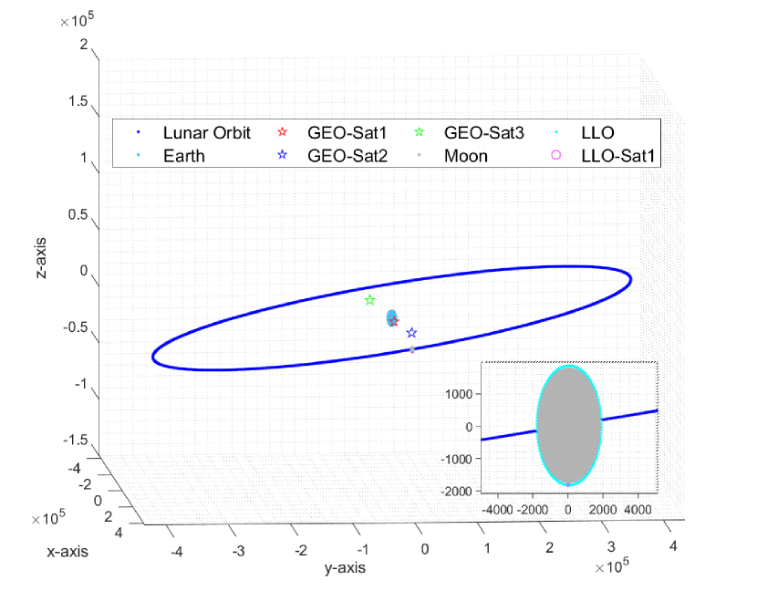
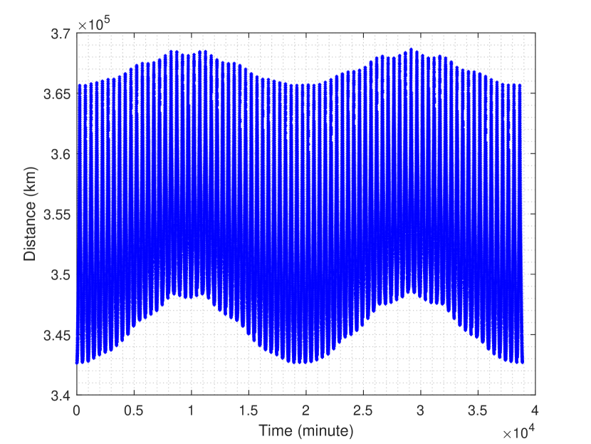
In this section, we present the system model for RIS-assisted cislunar communication, specifically designed to enhance the communication capabilities towards the Moon and beyond, as depicted in Fig. 1. The model encompasses a communication source aiming to transmit signals to a distant destination on the Moon with the aid of a RIS-equipped GEO satellite. The model delineates the communication path into two segments: from the source to the GEO satellite over a distance , and from the GEO satellite to the destination over a distance . To optimize the communication range, we exploit LLO with a inclination, which ensures shorter distances to the Moon, as shown in Figs. 2 and 3 [17].
The RIS technology utilized in this model is characterized by a passive surface with elements engineered to reflect signals directly toward the Moon. This approach leverages the inherent capability of RIS to manipulate signal paths effectively, thus enhancing the communication link’s overall performance 111There are many types of RIS architectures, including active, and passive, and beyond diagonal RIS (BD-RIS). In this paper, as the first attempt, we focus on the passive RIS, the most practical one among them..
As demonstrated in Fig. 2, our dynamic cislunar system model I simulation environment consists of the Earth, three equidistant satellites over the GEO, lunar orbit, the Moon, and a relay satellite moving around the Lunar Low Orbit (LLO) which is selected as perpendicular to the lunar equator [17]. The three equidistant satellites over GEO are positioned such that the time-varying Line of Sight (LoS) distance between the closest GEO satellite among the three and the LLO satellite is presented in Fig. 3.
The temporal and geometric parameters of our proposed cislunar communication system can be found in Table II and III, respectively. We resort to these parameters to construct our dynamic Cislunar system model shown in Fig.2.
| Temporal Parameters | Values | |
|---|---|---|
| Earth’s rotation | 1 day [18] | |
| Moon’s rotation | 27 days [19] | |
| Moon’s revolution | 27 days [19] | |
|
2 hours [17] | |
| Angular velocity of Earth | /min. [18] | |
| Angular velocity of Moon | /min. [19] | |
| Total simulation time | min. | |
| Sampling time | min. |
| Geometric Parameters | Values | ||
|---|---|---|---|
| Earth radius | km [20] | ||
| Moon radius | km [20] | ||
|
km [19] | ||
|
km [21] | ||
|
km [17] | ||
| Earth obliquity | [22] | ||
| Lunar obliquity | [22] | ||
| Lunar obliquity to ecliptic plane | [22] | ||
|
[22] |
II-A Signal Model
In RIS-assisted cislunar communication, a ground base station on Earth initiates communication with the Moon by sending the signal satisfying the power constraint . This transmission is uniquely facilitated by a RIS composed of elements, each endowed with the capability to adjust the signal’s phase via shifts denoted by for the -th element. The RIS’s function, captured in the phase shift matrix , ,
is pivotal in directing and enhancing the signal’s power toward its lunar destination. This journey unfolds in two principal stages: the signal’s initial travel to the RIS and its subsequent redirection to the Moon.
Overall, the signal model is given by [7]:
where is the channel from ground base station to the RIS, is the channel from RIS to the destination, and is the additive white Gaussian noise with variance . Moreover, is the abbreviation of , which represents the received signal power as the function of the channels, , and the path losses to be defined later. The corresponding SNR is then given by
| (1) |
II-B Path Loss Model
The path loss model involves the distances from Earth to the RIS and from the RIS to the Moon . Assuming a free-space path loss model for simplicity, the path loss for each of the two links can be represented as follows [23]:
i) From Earth to RIS:
ii) From RIS to Moon:
where with being the frequency of the transmitted signal and being the speed of light in a vacuum. Considering the RIS, the overall path loss for the signal from the ground base station to the Moon would be the product of these two path loss components, assuming they are independent.
Since all the links involved in such cislunar communication systems are LoS whose signal attenuations are already captured by path losses, we may assume that ; therefore, only their phases matter. The calculation of the received power can then be simplified by computing the effective area [24] as
| (2) | ||||
where the directivity gain related to the area of the RIS is with being a constant that translates the area into directivity gain, and is based on fundamental principles of antenna theory. Meanwhile, the efficiency of phase adjustments highlights the RIS’s ability to align its phases to focus the signal, where represents the deviation from an optimal phase alignment . This cosine squared function depicts the decline in efficiency as the phase alignment moves away from optimal.
| (3) |
This equation is fundamental in assessing the quality of the communication link, where a higher SNR indicates a clearer signal with less noise interference. In the next section, we formulate a constrained optimization problem that aims at maximizing the received SNR by optimizing .
III Problem Formulation and Proposed Solution
In this section, we introduce the problem as described in Section III-A and outline the solution in Section III-B.
III-A The Problem
The optimization problem for cislunar communication networks aims to maximize the SNR by strategically configuring RIS phase . The focus is on maintaining reliable communication over long distances by achieving the required SNR to ensure signal quality under specific environmental conditions, such as free-space loss and noise , thus ensuring efficient and sustainable operations for cislunar destinations.
The SNR equation underscores the critical importance of precise RIS phase rotation management to improve cislunar communications. The subsequent formulation demonstrates how RIS technology can enhance the reach and reliability of these networks,
| (4) | ||||
where the optimization constraints for enhancing wireless communication systems include constraint , which limits the minimum and maximum values for RIS phase rotation, and constraint , which governs the transmit power.
III-B Problem Solution
The maximization of SNR in RIS systems involves addressing the phase rotation of the RIS. We assume the effective area of the RIS, , is fixed at its maximum value, , which is fixed in the deployment phase and not the concern at this stage.
The critical factor for SNR maximization is the phase rotation, controlled through the RIS phases. Recall that
where is the phase angle that maximizes the SNR and represents the phase set on each RIS element.
To achieve maximum SNR, the cosine squared term must be maximized. This is achieved when:
This condition is satisfied when is an integer multiple of , leading to:
For practical purposes and simplicity, the most straightforward implementation sets , leading to
Therefore, the optimal matrix, which is a diagonal matrix of RIS phase angles, should be set to for each element. We note that in such a cislunar mission, determining is a geometry problem based on the relative positions of the Earth transmitter, RIS on the GEO, and the Moon. This is because all the links involved, including that from the Earth transmitter to the RIS and that from RIS to the Moon, are LoS. We thus assume that there is a real-time adaptive control system to keep track of this phase; hence, is known.
IV Simulation Results
In this section, we evaluate the performance of our proposed technique through extensive simulation results. Specifically, in Section IV-A, we provide the simulation setting, followed by the simulation results in Section IV-B.
IV-A Simulation Setting
Our study uses detailed simulation settings to explore how RIS elements affect SNR in different scenarios involving the communication source, RIS, and receiver. We thoroughly investigate the effects of various RIS configurations and distances on SNR, with the specific parameters of our analysis presented in Table IV.
| Parameter | Value/Description | Reference |
|---|---|---|
| Transmit power, 40 KW | [25] | |
| Calculated based on the equation provided | ||
| Gain of the transmitting antenna, e.g., 30 dBi | [26] | |
| Gain of the receiving antenna, e.g., 20 dBi | [26] | |
| Additional path loss due to RIS, e.g., 0.9 | [27] | |
| Noise level at the receiver, e.g., -100 dBm | [28] | |
| Wavelength of the transmitted signal, e.g., 0.03 m | [26] | |
| SNR threshold, e.g., 10 dB | [28] | |
| Maximum effective area of RIS, e.g., 100 m2 | [27] | |
| Between 0 and 2 | [27] | |
| Constant for directivity gain calculation, e.g., 0.1 | [28] | |
| various depending on factors defined |
IV-B Simulation Results
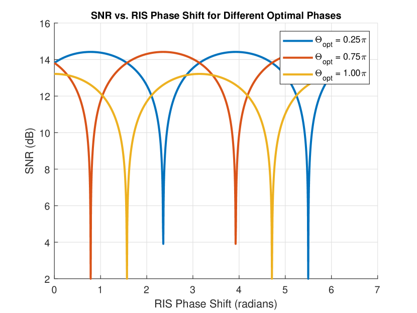

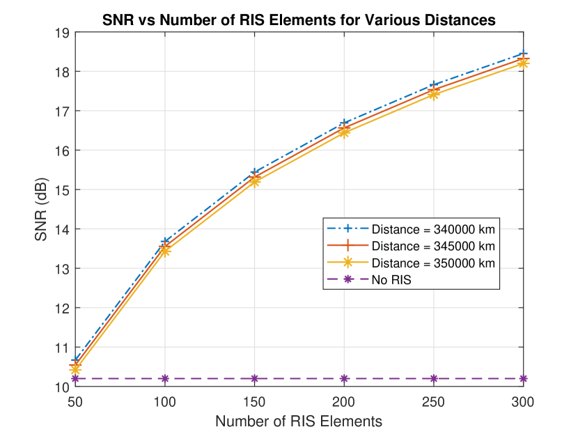
Fig 4 illustrates the correlation between SNR and RIS phase alignment, showcasing results for different optimal phase designing . The figure demonstrates how variations in the optimal phase significantly affect phase alignment, thereby impacting the overall SNR. This evidence highlights the critical role of selecting optimal phase shift controls in the design of RIS systems. Such optimizations are essential for enhancing communication link performance by fine-tuning the RIS configurations to their most effective states.
Fig 5 illustrates the relationship between SNR and the number of RIS elements, evaluated for different distances illustrated in Fig 3. The results indicate that an increase in the number of RIS elements leads to higher SNR. From the perspective of distance, it is observed that SNR is greater at shorter distances, which aligns with expectations. This underscores the effectiveness of utilizing RIS to enhance the received SNR, thereby extending cislunar coverage.
Using again the SNR vs the number of RIS elements, Fig 6 compares the RIS-aided cislunar communication systems with those without RIS. Due to the lack of LoS between the Earth transmitter and the Moon, the cislunar system relying solely on direct path fails terribly, while the RIS-aided systems yield substantial SNR gains. The results highlight the significant role of RIS in cislunar communication systems.
V Conclusion
This study introduced an innovative methodology to enhance cislunar communications by utilizing RIS. It addressed challenges such as signal attenuation and the need for precise directivity and signal convergence, which are critical in cislunar communication systems. The research focused on the optimization of the SNR for signals transmitted between the Earth and the Moon. Through the derivation of a closed-form solution, the optimal phase configuration for RIS was identified, leading to a substantial improvement in signal clarity. The findings revealed the significant benefits of adopting optimal RIS configurations. Potential future works include expanding to include diverse RIS-assisted communication scenarios such as multiple antenna systems, investigating various RIS technological architectures such as BD-RIS, and employing machine learning algorithms to refine RIS configurations further.
References
- [1] M. Y. Abdelsadek, A. U. Chaudhry, T. Darwish, E. Erdogan, G. Karabulut-Kurt, P. G. Madoery, O. Ben Yahia, and H. Yanikomeroglu, “Future space networks: Toward the next giant leap for humankind,” IEEE Transactions on Communications, vol. 71, no. 2, pp. 949–1007, 2023.
- [2] G. Xu and Z. Song, “Effects of solar scintillation on deep space communications: Challenges and prediction techniques,” IEEE Wireless Communications, vol. 26, no. 2, pp. 10–16, 2019.
- [3] M. M. Puumala, O. Sivula, and K. Lehto, “Moving to Mars: The feasibility and desirability of Mars settlements,” Space Policy, vol. 66, p. 101590, 2023.
- [4] M. Giordani and M. Zorzi, “Non-terrestrial networks in the 6G era: Challenges and opportunities,” IEEE Network, vol. 35, no. 2, pp. 244–251, 2020.
- [5] S. Gallozzi, D. Paris, M. Scardia, and D. Dubois, “Concerns about ground based astronomical observations: quantifying satellites’ constellations damages,” arXiv preprint arXiv:2003.05472, 2020.
- [6] M. Toka, B. Lee, J. Seong, A. Kaushik, J. Lee, J. Lee, N. Lee, W. Shin, and H. V. Poor, “RIS-Empowered LEO satellite networks for 6G: promising usage scenarios and future directions,” arXiv preprint arXiv:2402.07381, 2024.
- [7] S. G. Cetin, G. Karabulut-Kurt, and A. Vazquez-Castro, “Secure and robust communications for cislunar space networks,” arXiv preprint arXiv:2310.09835, 2023.
- [8] B. Donmez and G. Karabulut-Kurt, “Continuous power beaming to lunar far side from EMLP-2 Halo orbit,” arXiv preprint arXiv:2402.16320, 2024.
- [9] E. Koktas and E. Basar, “Communications for the planet mars: Past, present, and future,” arXiv preprint arXiv:2211.14245, 2022.
- [10] E. Koktas, R. A. Tasci, I. Yildirim, and E. Basar, “Unleashing the potential of reconfigurable intelligent surfaces in martian communication,” 2023.
- [11] K. Tekbiyik, G. Karabulut-Kurt, A. R. Ektı, and H. Yanikomeroglu, “Reconfigurable intelligent surfaces empowered THz communication in LEO satellite networks,” IEEE Access, vol. 10, pp. 121 957–121 969, 2022.
- [12] K. Tekbıyık, G. Karabulut-Kurt, A. R. Ekti, and H. Yanikomeroglu, “Reconfigurable intelligent surfaces in action for nonterrestrial networks,” IEEE Vehicular Technology Magazine, vol. 17, no. 3, pp. 45–53, 2022.
- [13] A. M. Huroon, Y.-C. Huang, and L.-C. Wang, “UAV-RIS assisted multiuser communications through transmission strategy optimization: GBD application,” IEEE Transactions on Vehicular Technology, pp. 1–14, 2024.
- [14] E. Björnson, H. Wymeersch, B. Matthiesen, P. Popovski, L. Sanguinetti, and E. de Carvalho, “Reconfigurable intelligent surfaces: A signal processing perspective with wireless applications,” IEEE Signal Processing Magazine, vol. 39, no. 2, pp. 135–158, 2022.
- [15] Q. Wu and R. Zhang, “Intelligent reflecting surface enhanced wireless network via joint active and passive beamforming,” IEEE Trans. Wireless Commun., vol. 18, no. 11, pp. 5394–5409, 2019.
- [16] X. Cao, B. Yang, C. Huang, C. Yuen, M. Di Renzo, D. Niyato, and Z. Han, “Reconfigurable intelligent surface-assisted aerial-terrestrial communications via multi-task learning,” IEEE J. Sel. Areas Commun., vol. 39, no. 10, pp. 3035–3050, 2021.
- [17] R. Whitley and R. Martinez, “Options for staging orbits in Cislunar space,” in IEEE Aerospace Conference, 2016, pp. 1–9.
- [18] “Chapter 2: Reference Systems - NASA Science.” [Online]. Available: https://science.nasa.gov/learn/basics-of-space-flight/chapter2-1/
- [19] “Moon Facts - NASA Science.” [Online]. Available: https://science.nasa.gov/moon/facts/
- [20] “Moon Fact Sheet.” [Online]. Available: https://nssdc.gsfc.nasa.gov/planetary/factsheet/moonfact.html
- [21] “3. The geostationary orbit.” [Online]. Available: https://www.esa.int/Education/3._The_geostationary_orbit
- [22] C. Olthoff, D. Kaschubek, and M. Killian, “Dynamic thermal interactions between spacesuits and lunar regolith in permanently shaded regions on the moon,” Acta Astronautica, vol. 203, pp. 351–369, 2023.
- [23] J. Jeong, J. H. Oh, S. Y. Lee, Y. Park, and S.-H. Wi, “An improved path-loss model for reconfigurable-intelligent-surface-aided wireless communications and experimental validation,” IEEE Access, vol. 10, pp. 98 065–98 078, 2022.
- [24] E. Björnson, Ö. T. Demir et al., “Introduction to multiple antenna communications and reconfigurable surfaces,” 2024.
- [25] M. Qaraqe, M. Usman, A. Serbes, I. S. Ansari, and M.-S. Alouini, “Power hotspots in space: Powering cubesats via inter-satellite optical wireless power transfer,” IEEE Internet of Things Magazine, vol. 5, no. 3, pp. 180–185, 2022.
- [26] B. Donmez, I. Azam, and G. Karabulut-Kurt, “Mitigation of misalignment errors over inter-satellite fso energy harvesting,” in IEEE 34th Annual International Symposium on Personal, Indoor and Mobile Radio Communications (PIMRC). IEEE, 2023, pp. 1–5.
- [27] W. Tang, M. Z. Chen, X. Chen, J. Y. Dai, Y. Han, M. Di Renzo, Y. Zeng, S. Jin, Q. Cheng, and T. J. Cui, “Wireless communications with reconfigurable intelligent surface: Path loss modeling and experimental measurement,” IEEE Transactions on Wireless Communications, vol. 20, no. 1, pp. 421–439, 2021.
- [28] M. Jesick, “Mars trojan orbits for continuous Earth-Mars communication,” The Journal of the Astronautical Sciences, vol. 67, pp. 902–931, 2020.