Erasure-tolerance protocol for the surface codes on Rydberg atomic quantum computers
Abstract
Rydberg atom array with optical tweezers is a promising candidate for a fault-tolerant quantum computer, thanks to its good properties such as scalability, long coherence time and optical accessibility for communication. A big barrier to overcome is non-Pauli errors, erasure errors and leakage errors. Conventional work has revealed that leakage error is convertible to erasure error. A remaining problem is that such (converted) erasure errors continuously happen and accumulate. The previous proposal involved transporting atoms directly from the reservoir area, where atoms are stored for spare, to the computational area, where the computation and the error correction are processed, to correct atom loss. However, transporting atoms takes a long time and has side effects on surrounding qubits in practice. In this study, we evaluate the effects on planar code by circuit-based Monte Carlo simulation which has depolarizing errors and erasure errors, and propose a new scheme to tolerate that problem, namely, -shift erasure recovery scheme. Our scheme uses online code deformation to tolerate erasures and repeatedly transfers the logical qubit from an imperfect array in which erasure errors accumulated to another perfect array in which erasure errors have been fixed by offline optical tweezers, to tolerate a large (accumulated) number of erasures. Furthermore, our scheme corrects erasure errors of atom arrays while logical qubits are evacuated from that area to correct; therefore, manipulating optical tweezers for erasure correction does not disturb qubits that compose logical data. We believe that our scheme provides practical directions for Rydberg atom quantum computers to realize feasible fault-tolerance.
I Introduction
Scalable and universal quantum computers are expected to be the computers for the next generation beyond classical computers. Rydberg atomic quantum computers are particularly promising candidates for scalable quantum computers, as they demonstrated key functionalities required for fault-tolerant quantum computation [1, 2]. Rydberg atoms have desirable properties as qubits, such as long coherence time and high controllability in the array. However, there are typical hurdles to overcome, erasing of atoms, which is the disappearance of qubits caused naturally by the escape of atoms on which the qubit is encoded from optical tweezers, and leakage errors, which are the leakage of atom states from computational quantum state space caused by such as imperfect operation of Rydberg interactions applied to execute quantum gates.
In addition, it has been shown that leakage errors and atom loss are detectable by Rydberg gates [3], and a method to convert leakage errors to erasure errors by Rydberg excitation has also been proposed [4, 5]. Thus, the atom loss and leakage errors can be treated as erasure errors by the above techniques.
Fortunately, surface codes are known to have a tolerance to erasure errors using super stabilizers [6, 7]. However, those studies have not revealed the limitation of surface code when erasure errors increase dynamically and accumulate on an array. This behavior is commonly observed in Rydberg atom quantum computers. Another problem in acquiring the erasure tolerance for surface code is how to refill vacant spots with atoms. In previous studies, atoms were refilled directly into the online array on which some error correction code is encoded [3, 4]. However, this procedure may have problematic side effects; it may cause erasure errors when the transposed atoms are close to other atoms on the array ( ) [8]. It means that refilling atoms directly into the online array causes additional errors if an error-correcting code such as surface code is implemented on a dense array. Repairing erased atoms may result in a high possibility of transversal Pauli error chains which is a typical source of the logical error of the surface code, leading to a high logical error rate.
In this study, we evaluate the performance of planar code which has depolarizing errors and dynamically accumulating erasure errors by circuit-based Monte Carlo simulation. The simulation shows that the surface code on the array, on which vacant spots can be refilled only when it is offline, does not have the threshold of logical error rate and has just a pseudo-threshold of physical error rate for logical error rate. The reason why our surface code has the pseudo-threshold, not the threshold, is that the number of operations increases and because the accumulated erasure errors increase on the array. The surface code repeats error syndrome measurements and decoding as many times as the code distance to correct Pauli errors on ancilla qubits and measurement errors. As a result, the number of accumulated erasure errors on the array increases along with the time executing the error detecting and correcting operations of surface code.
To solve this problem, we propose a new scheme to modify erasures, namely -shift erasure recovery. Our scheme protects the logical state from erasure errors by combining the code deformation technique of the surface code, which are extension and contraction operations, and the atom transportation to rearrange or refill atoms on the array. This scheme maintains the array without caring about the decoherence of qubits caused by the atom transportation of tweezers, thanks to separating the operation to maintain the logical qubit from the maintenance of the atom array. This transportation of a logical qubit is realizable by not only lattice surgery but also quantum teleportation using transversal CNOT gates.
Our scheme helps to develop Rydberg quantum computers into fault-tolerant quantum computers by protecting a logical quantum state from both Pauli error and erasure error.
II Rydberg atom qubits 2-D array and its error model
The atomic spices used in the neutral atom quantum computer are alkali metals such as Rb and Cs, and alkaline earth metals such as Yb and Sr. These atoms are called Rydberg atoms because their interactions are controllable by being excited to Rydberg states which are states of a large principal quantum number. Using this interaction, multi-qubits gates can be implemented by Rydberg blockade [9, 10].
An optical tweezer is a technique to trap a single atom on a spot focused m width, which is shaped by a spatial light modulator (SLM), an acousto-optic deflector (AOD), and an objective lens [10]. The tweezer array can arrange many single atoms at once and can control the shape of the array and the distance between atoms freely [11]. In addition, it is possible to transport a single atom by moving the optical tweezer potential by manipulating SLM and AOD [1].
II.1 Rydberg atom qubits
A single atom has multiple energy levels, and two of them are determined to define a qubit, such as the levels on a hyperfine structure. An arbitrary single-qubit gates are realized using Rabi oscillation on qubit sublevels [10]. Multi-qubit gates are realized via a dipole-dipole interaction between Rydberg states, and they are called the Rydberg gates. Let be the distance between atoms. The dipole-dipole interaction decreases depending on . The Rydberg gates are applicable among atoms which are not necessary to be nearest-neighbors in the array as long as they are close enough for the dipole interaction to act effectively. The typical two-qubit gate of Rydberg gate is CZ gate [9]. A CNOT gate is achievable by a CZ gate headed by and followed by Hadamard gates to the target qubit. Combining those arbitrary single-qubit gates and multi-qubit gates, a universal quantum gate set is achieved on Rydberg atom quantum computers.
II.2 Leakage errors and atom loss on neutral atom qubits, and Erasure errors
Atomic quantum computers with optical tweezer arrays are not only exposed to Pauli errors on the qubit space but also leakage errors where the state leaks to outside levels of the qubit space, and atom loss where atoms are erased, such as disappearing from optical tweezer sites. Some leakage states can be corrected to the qubit space by optical pumping [3], and other leakage errors can be converted to erasure errors if their occurrence is detected [4]. The experiment on a 2-electron neutral atom has demonstrated the erasure conversion protocol for leaked states of radiative decay and blackbody radiation error [5].
The atom loss is the atom’s disappearance from the tweezer site. The existence of an atom on the site is detectable by quantum circuits such as shown in Fig. 1 with an ancilla qubit [3]. Thus, atom loss can also be treated as erasure errors.
Combining those discussions, both leakage errors and atom loss are treated as erasure errors as long as their occurrence is detectable. By erasure error, quantum states are mapped to non-qubit space by probability , i.e.
| (1) |
where is a state on non-qubit space [12].
In the case of the CZ gate operation with a completely erased qubit, the CZ gate does not work at all, so it is equivalent to the Identity gate, so it does not cause state error.
\Qcircuit@C=1em @R=.7em
\lstick—+⟩ (ancilla) & \ctrl1 \qw \ctrl1 \qw \measure
\lstickData \ctrl-1 \gateX \ctrl-1 \gateX \qw
III Surface code with erasure errors
III.1 Surface code
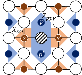
The surface code is one of the topological quantum error correction codes [13, 14]. Let us consider a qubit array arranged on a square lattice in which the data qubits (white circle) are on each edge and the ancilla qubits for the error syndrome measurements (blue and orange circle) are on face and vertex as shown in Fig. 2a. To define the stabilizer group of the surface code for an ideal array without erasures , we define the star and plaquette operators
| (2) |
where are the vertices, edges, and faces of the square lattice, and are the boundary operators of the square lattice and its dual lattice, respectively. The boundary of the code is classified into two types, called the smooth boundary where ends up, and the rough boundary where ends up.
III.2 Error detection and decoding
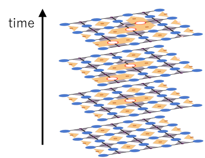
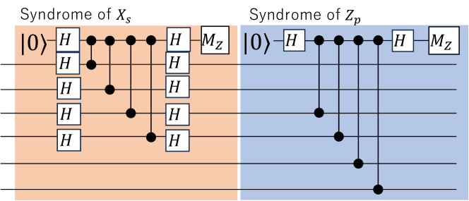
The encoded state is stabilized by as constructed above. The errors on this state are determined by the measuring eigen-values corresponding to the stabilizer generators whether or , which provides information about the Pauli errors that occurred in the qubit array. By performing indirect measurements of the star (plaquette) operator as in Fig. 2c via the orange (blue) auxiliary qubits in Fig. 2a, we obtain this information. This measurement is called syndrome measurement. A set of one trial of syndrome measurement corresponding to each element of constructed as above is called Big-T. For a planar code with code distance , perform sets of Big-T syndrome measurements.
Even if measurement errors occur during syndrome measurements, repeating syndrome measurements times makes the logical qubit tolerant against measurement errors.
The error syndromes contain the information of errors. To decode those syndromes into Pauli errors, we form the graph as shown in [15] and it is called a Nest. At first, regard each syndrome as a vertex in . Then, Connect these vertices to the edge that corresponds to a spacial, Pauli error on each data qubit. Also, connect the vertices to edges each of which corresponds to a temporal measurement error of each syndrome. By estimating the most likely pairs for the vertices where the syndrome measurement outcomes flip, to or to on the Nest, both computation errors and measurement errors are detected and corrected. There are algorithms to estimate the most likely pair for the vertices [15, 16, 17]. A typical algorithm is the Minimum Weight Perfect Matching (MWPM) [18].
III.3 Previous works for erasure errors
Erasure errors can be classified into three: static erasure errors, dynamic erasure errors which can be corrected immediately, and dynamic erasure errors which cannot be corrected immediately.
III.3.1 Static erasure errors
In a system where erasure errors happen statically, you can know the position of erasure errors before executing quantum computation and the number of erasure errors, and they are not changed during the execution. The typical case of static erasure errors is the fabrication error of such as superconducting quantum circuits [7, 19]. Static erasure errors are not errors occurring during computation but imperfections occurring before the computation. However, the static erasure error has many points in common with erasure errors: the absence of qubits causes them, their locations are heralded, and stabilizer modification is required to deal with them, as explained in the following sections. This type of erasure can be corrected by super stabilizers. There are two ways to construct super stabilizers, Stace and Barrett method [6] and Nagayama method [7]. The idea of Stace and Barrett’s method is simple and easy to construct super stabilizers. The super stabilizers can be made by multiplying stabilizers related to erased data qubits like Fig. 2a. The star and plaquette stabilizers are merged into a super stabilizer in the same way, which means the deployment of it is symmetric. This method generates junk qubits as side effects, which are created on the extra degree of freedom caused by reducing two stabilizers for an erased data qubit. The super stabilizers decrease the threshold of state error rate even though junk qubits do not cause logical errors. On the other hand, Nagayama’s method, in which super stabilizers and weight-reduced stabilizers are used together, is an improved version of Stace and Barrett’s method. This method does not generate junk qubits, but the deployment of super stabilizers is asymmetric.
III.3.2 Instantly correctable erasure error
Some systems may have erasure errors happening dynamically during computation. In this case, the number of erasure errors changes during the computation. Mechanisms to detect the positions of erased qubits have been investigated, depending on the physical and architectural systems [20, 3, 4]. There are two types of erasure errors, i.e., in some systems, erasure errors remain, and in others, they don’t.
A typical example of the first type is neutral atom quantum computers; erasure errors remain unless special operations are executed to fix erasure errors. Such a special operation is, i.e., to refill the erased position with a new atom instantly. Such refilling is achieved by conveying atoms with optical tweezers. In the erasure conversion approach [4, 21], the qubit information is exactly erased, but the atom may remain in its position. In that case, it works to get erased qubits, which are in a completely mixed state, incorporated with the surrounding stabilizers, and projected to the proper code word state of the quantum error correcting code. However, conveying atoms with optical tweezers in this approach may disturb qubits along the path across the atom arrays.
A typical example of the latter type is one-way quantum computation with a 3-D cluster state [22, 20]. Because all qubits are going to be measured and disrupted anyway, erasure errors in a layer corresponding to a Big-T do not remain in the next Big-T. Thus, this model has the erasure-tolerance of up to erasure rate [22], though we don’t actually ”correct” the erased qubits.
III.3.3 Accumulating, dynamic erasure errors
Some systems, typically neutral atom array quantum computers, cannot correct dynamic erasure and leakage errors sequentially after detecting their events since conveying atoms into the online array disturbs other qubits. Consequently, the number of erasure errors in the arrays increases over time. In such cases, the surface code doesn’t work properly because the distribution of erased qubits always changes over time, and error detection and decoding don’t work properly around erased qubits.
In this study, we propose a scheme of surface code to deal with dynamic erasure errors and leakage errors that cannot be corrected in ordinary error correction cycles. This model corresponds to the Rydberg atomic quantum computer with optical tweezer arrays, which cannot convey atoms to the online array on which logical qubits are encoded.
IV Error correction under accumulated dynamic erasure errors
IV.1 The main problem
Let us consider the situation where the erasure errors occur dynamically and cannot be corrected sequentially after detecting erasures. This situation corresponds to the Rydberg atomic quantum computer with optical tweezer arrays, which cannot convey atoms to the online array on which logical qubits are encoded because it may cause adverse effects such as decoherence or repulsion between atoms.
IV.2 Generating stabilizer generators
In the case of the erasure errors occurring on the data qubits, you can maintain the function of the error correction by removing stabilizer generators related to the erased data qubits from the stabilizer group and adding the super star (plaquette) operators to the stabilizer group by multiplying the removed stabilizer generators. Here, we use Stace’s method to compose stabilizers into a super stabilizer. Let us assume that a data qubit has been erased, as in the center of Fig. 2a. Two star stabilizer generators act on this erased data qubit, let’s call them . To exclude the erased data qubit from the code, we remove and from and add
| (3) |
to . On the plaquette stabilizer side as well, two stabilizers share the erased data qubit. Thus, you can compose these in the same way. Even when multiple erasures exist, instead of the stabilizers that share the erased data qubits, we can insert the stabilizer created by multiplying them to generate the deformed stabilizer group. We denote the new generators formed in this way as . The stabilizer group , which have as their generators, newly stabilize the planar code state of the qubit array containing erasures.
IV.3 Composition of super stabilizer and decoding on dynamic erasure
Dynamic erasure errors may occur while executing the stabilizer circuits. Therefore, we should perform erasure detection before measuring syndromes for all stabilizer generators, i.e., just before each syndrome measurement in each Big-T. Based on the distribution of detected erased qubits, we can construct the super stabilizer as described above and then perform syndrome measurements corresponding to the stabilizer generators that include the super stabilizer. Let us consider updating the stabilizer generators for each Big-T to adapt to erasure errors dynamically occurring. We have to detect erasure errors and their distribution on the array in every Big-T to compose the stabilizer generators based on the result of detecting the erasure distribution. The procedure to compose the stabilizer generator is described in Chap. IV.2. In this study, to efficiently find the stabilizer pair to be composed, we compose them using the Union Find algorithm, as described in the pseudo-code in Algorithm. 1.
For a surface code with a code distance of , we repeat syndrome measurements and erasure detections times as described in Chap. III.2, and based on these results, we create a Nest . If an erasure error occurs to a data qubit, we can create a Nest adapting to the super stabilizer by setting the weight of the corresponding edge to [6, 22]. In our error model, erasures accumulate, unlike the model in [22]. Thus, once an erasure error occurs, the weight of the edge is kept to be after that. By matching vertices where the eigenvalues in syndrome measurement flip with a Minimum Weight Perfect Matching (MWPM) problem solver in , we can estimate where the Pauli errors happen.
V Numerical simulation and its analysis
V.1 Error models and assumptions in our simulation
In our simulation, we performed a circuit-based Monte Carlo error simulation to investigate the behavior of logical error and catastrophic corruption of the array. We considered Pauli errors, which occur in the qubit space, and erasure errors for errors occurring in physical qubits. We assumed that the Pauli errors occurring in the qubit space are depolarizing errors. The depolarizing error on a single-qubit is defined as an error channel where the three Pauli operators are applied with equal probability , i.e.,
| (4) |
Similarly, the depolarizing error that acts on two-qubits with probability is defined as,
| (5) |
Here, the set is,
| (6) |
.
As described above, the erasure and heralded leakage errors can be considered an erasure error channel as Equation (1). In this simulation, we assumed that both erasure and leakage errors can be detected simultaneously before performing the syndrome measurement for all ancilla qubits and that the leakage error can be converted to an erasure error. Erasure errors occur with probability for each gate operation, and once an erasure occurs, it cannot be recovered immediately. This model corresponds to the situation involving difficulties in refilling single atoms to the atomic tweezer array, such as additional erasure caused by the tweezer transportation [8].
V.2 Composition of super stabilizers
We determine the stabilizer generators to be composed based on the results of the detected erased qubits. We compose the stabilizer generators using Stace’s method. We find the set of stabilizer generators to be composed with a Union Find structure, as shown in the pseudo-code in Algorithm 1. We can use this algorithm to generate a stabilizer generator for a system with erasure in for the number of qubits .
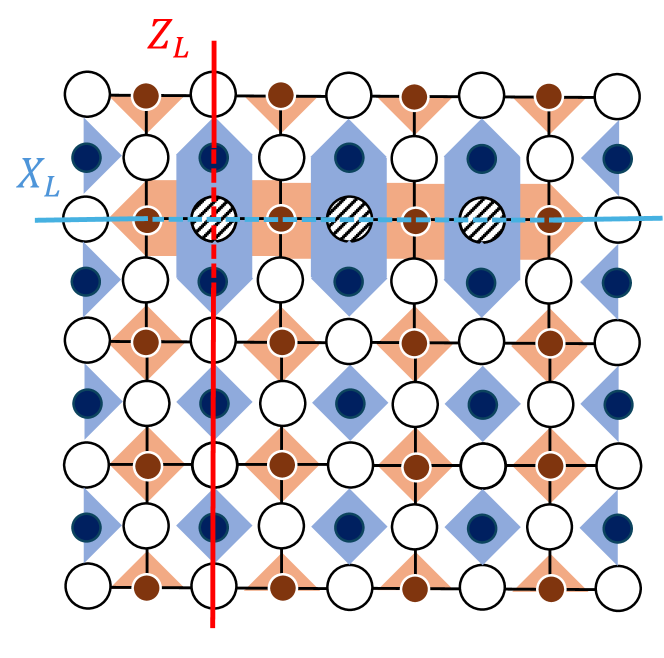
The composition of the stabilizer generators reduces the effective code distance. The length of the shortest logical operator (composed of corresponding physical operator chain; hence, we can discuss the length of logical operators here) that transverses the larger stabilizer generator to be composed of normal ones is shorter than the shortest logical operator on the usual surface code with no erasures. The existence of a shorter logical operator means that the effective code distance becomes shorter. If the erasure errors happen continuously between the boundaries such as Fig. 3, a larger stabilizer generator that connects between boundaries will be composed. This lattice no longer has enough code distance and does not have a logical qubit to tolerate Pauli errors, i.e., the effective code distance becomes . Therefore, if erasure errors exist across the array, we grant that the logical qubit has been destroyed in this study.
Ancilla qubits are also exposed to erasure errors. However, its effect is possibly mitigated by reusing ones for other stabilizers because ancilla qubits can be shared by multiple stabilizers because they are initialized every time they are used. Thus, we check whether any ancilla held by the super (or normal) stabilizer is alive, and if it is not, we try to find a sharable ancilla qubit placed within the second nearest neighbor of the original ancilla qubit. If any sharable ancilla qubit is not found, we regard this logical qubit as also destroyed.
V.3 Decoding Pauli errors
The nest gets a more irregular shape in every Big-T by composing some stabilizer generators to super stabilizers as described above. To adopt this deformation, vertices in get removed or merged. Actually, by setting the weight of the edge corresponding to erased data qubits on the nest to , matching and decoding of including the super stabilizers is still possible [6]. For a surface code with a code distance of , we perform erasure detections and syndrome measurements times. After that, we created a Nest as described above, in which vertices hold the flips of measurement results. We used the Minimum Weight Perfect Matching (MWPM) Decoder to decode error syndromes in the Nest into error placements in our simulation [18].
We first check if a logical qubit was destroyed due to erasure errors and then whether a logical Pauli error occurred. We can acquire the complete error distribution by tracking the Pauli frames, which are exactly the error information, classically in simulation, in contrast to real devices. The occurrence of the logical error is determined by the parity of the number of error chains crossing the logical operator on a boundary. The information of error syndromes involves perfect syndrome measurements at the last Big-T, not to misunderstand correctable, computational errors as measurement errors.
V.4 Numerical results
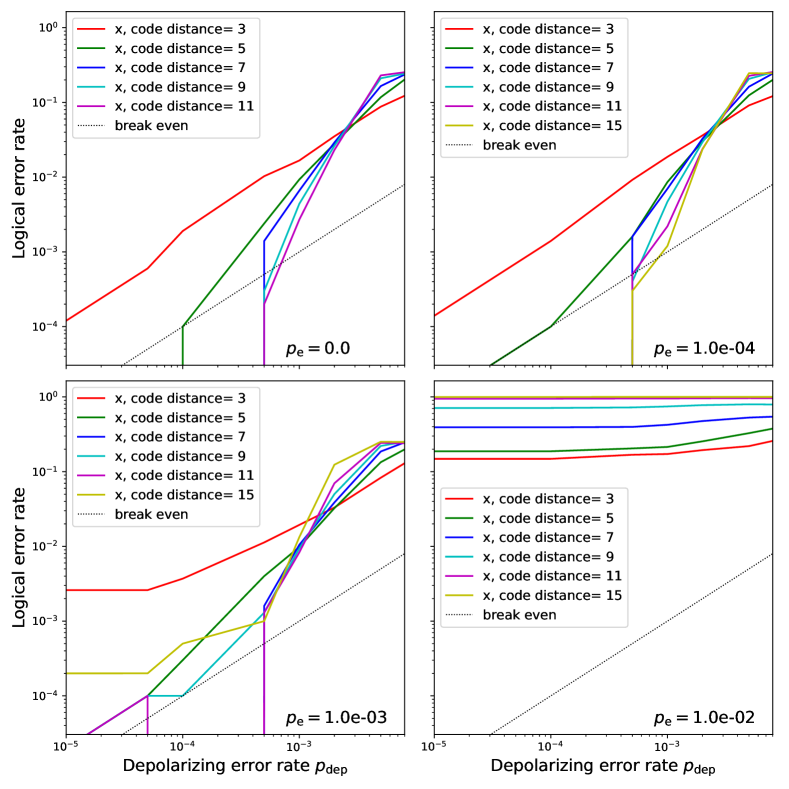
First, we calculated the threshold between the logical qubit error rate and the physical Pauli error rate, for each erasure error rate. The result of sweeping with fixed is shown in Fig. 4. The results show that qubits cannot tolerate the increase in erasure error rate, depending on the number of repetitions of Big-T which depends on the code distance if the erasure error rate is too high. This model has just a pseudo-threshold, which is the threshold-like behavior around the crossing point-like region, even if the model, in principle, does not obey the threshold theorem in the asymptotic limit. Each data point in the graph is calculated from the number of error events in attempts, each of which executes the whole circuit, i.e., . Note that the numerical results are not smooth in the region of small . This is because the logical error probabilities in this region were too low to acquire enough error events in numerical simulation to make the graph smooth.
It is known that this error model does not have a threshold for erasures () analytically. The ratio of qubits disappearing after repeating Big-T times, which applies gates to a qubit, is
| (7) |
Therefore, in the limit of , . This means that erasure errors cannot be attenuated, regardless of how much the code distance is extended, as long as erasure errors continue to accumulate.
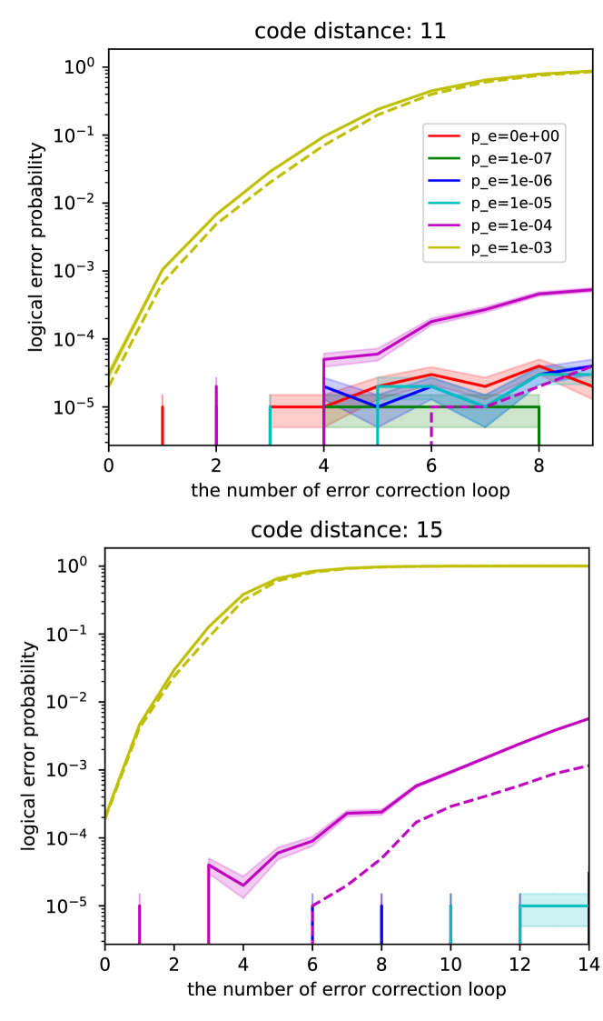
We also calculated the evolution of the logical error rate when decoding and error correction operations are repeated. The Fig. 5 shows the evolution of the logical error rate against the number of error correction (Big-T) loops when the depolarizing error rate per each gate operation is fixed at and the erasure error rate per each gate operation is shifted from to . It can be seen that the logical error rate increases with the accumulation of erased physical qubits in the array, particularly as error detection and correction operations are repeatedly performed. Also, the Fig. 5 shows that there are many occurrences of the logical qubit destruction due to array destruction or the absence of alternative ancilla qubits when the erasure error rate is high or when the code distance is extended. This is because the longer the code distance, the deeper the circuit is to correct measurement errors, increasing the ratio of erased qubits on the array. Meanwhile, the figure shows that the logical error rate is suppressed by extending the code distance in some parameter regions.
VI -shift erasure recovery
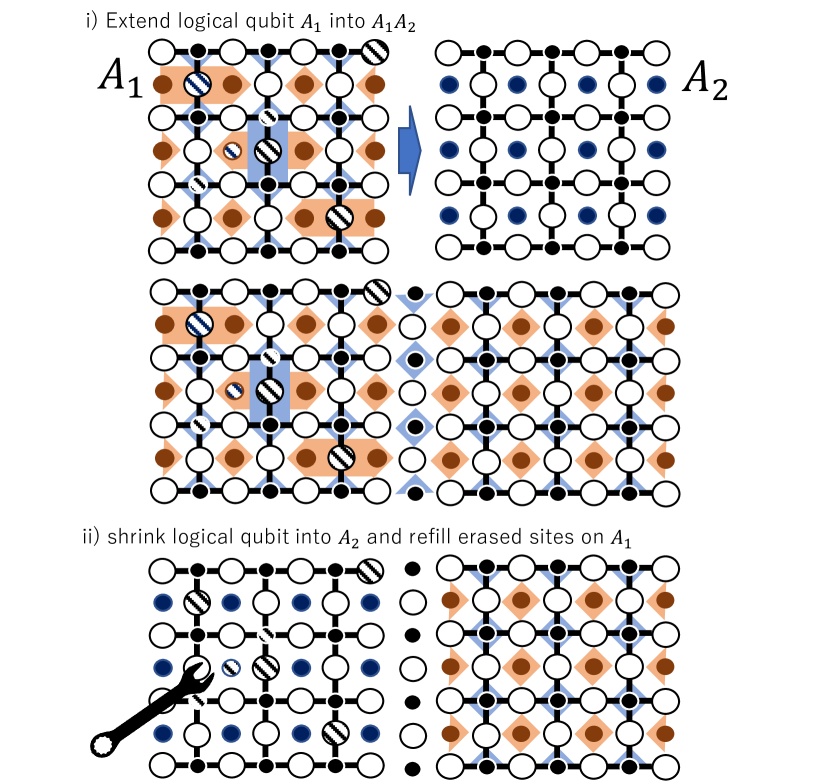
Our numerical simulation demonstrated that the repetition of the stabilizer circuit accumulates erased qubits, the effective code distance decreases continuously, and finally, the code loses the Pauli error tolerance required. If these erased qubits accumulate too many, it becomes impossible to correct errors properly. To solve this problem, we propose moving the logical qubit from the atom array with accumulated erasure errors to a new atom array free from erased qubits by combining the expansion and reduction operations of the surface code by code deformation [14] as shown in Fig. 6, namely, -shift erasure recovery. Our proposal is a series of two steps below:
-
1.
Repeat the surface code procedure tolerable against state errors, leakage errors, and erasure errors and execute quantum computation, with adapting accumulating erasure errors.
-
2.
Transfer the logical qubit to another perfect atom array when the amount of erasure errors likely makes the error tolerance of the surface code below the required level of error tolerance. Then, refresh the old atom array that contains erased qubits to make the atomic qubit array perfect again.
This series of steps divides the functionality to execute quantum computation with protection against state errors and endure against erasure errors, and the functionality to correct erasure errors. Our scheme makes the logical qubit not suffer from the unexpected effects caused by fixing the atom array by evacuating the logical qubit from the imperfect array.
Consider a qubit array on which a logical qubit of the planar surface code is encoded, and another qubit array on which nothing is encoded exist at first. We must iterate its syndrome measurement and error correction to correct Pauli errors on . However, this iteration increases the erasure ratio and finally makes its logical error rate higher than the requirement, such as [23]. Our protocol performs code deformation to move the logical qubit on to the new perfect array before the logical error probability of the logical qubits becomes higher than the required error rate, due to the accumulation of erased qubits. First, initialize qubits in appropriately to or . Then, perform syndrome measurements and decode and correct errors based on the measurement results to complete expansion of the logical qubits of the size on into logical qubits of crossing on and . After that, measure the data qubit on in or basis depending on the direction of the boundary expanding, to complete shrinking the logical qubit to the size on . From the result of direct measurement on data qubits, determine and record the parity of the or logical operator.
Now, qubits in do not hold logical information. So, we can execute any operation to the qubits, even destructive operations, without any concerns. Thus, the imperfect array with erased qubits in can be recovered by rearranging or refilling the array with a single atom from the atom reserver. For neutral atom array quantum computers, optical tweezers have been demonstrated to work well for such precise movement and insertion of atoms [24]. Our scheme separates the places to maintain the coherence of the logical qubits via syndrome measurements and the places for physical operations possibly destructive to quantum data to repair the array, such as rearrangement and refilling the array with atoms via tweezers. This provides us with the capability of taking more aggressive rearrangement strategies than the method of sequentially replenishing erased qubits.
In the same way, the erased qubit on the new array will increase after repeating the error correction. Again, we can make the system resistant to erasure errors by transferring the logical qubit to another array before the logical error probability becomes too high due to the same reason above. The explanation above uses just two pieces of qubit array and corresponds to -shift erasure recovery. This procedure can be expanded to -shift erasure recovery with pieces of qubit array, depending on the time needed to fix erasures on the array and the time until the array can no longer tolerate the accumulation of erasure errors and Pauli errors. We name this scheme ”-shift erasure recovery.”
VII Discussion and Conclusion
In this paper, we have numerically verified the error correction of surface codes on systems where erasure errors continuously occur, such as neutral atom quantum computers using optical tweezer arrays. Our work revealed that the threshold for erasure probability is theoretically because the accumulation of erasure errors cannot be stopped and because erased qubits cannot be corrected unless they are offline arrays. In addition, it is also revealed that the logical error probability can be suppressed by increasing the code distance and repeating error correction if the erasure error rate is sufficiently low. However, iterating the syndrome detection and correction operations increases the number of erased qubits even if on such parameter regions. To solve the problem that error correction becomes impossible due to the accumulation of erased qubits, we proposed the -shift erasure recovery scheme to protect the logical qubit from erasure by transferring the logical qubit to a perfect array using code deformation.
Our scheme allows us to rearrange physical qubits without concern about their decoherence caused by the transportation of physical qubits, which occurs as a side effect of the transport of atoms. Our scheme separates the rearrangement of qubits, which is too noisy for surrounding qubits, from the coherence-preserving operation of logical qubits. This separation allows for a more daring rearrangement strategy than conventional methods, such as sequentially replenishing erased qubits.
In the following, we discuss what we have not considered in this study and the open problems. The numerical calculations were performed assuming that each operation’s probability of erasure errors is uniform. However, it is known that the Rydberg atomic quantum computer is prone to leakage errors and erasure of qubits when performing 2-qubit gates [4]. Therefore, it is a future work to investigate the effect of bias on the erasure error probability.
It is also necessary to investigate the efficient scheduling and allocating of ancilla qubits for syndrome collection under this scheme. Rydberg gates allow syndrome collection with more efficient circulation of ancilla qubits and more efficient scheduling of syndrome measurements than the recent study that assumes only nearest-neighbor interactions [7] Additionally, The atomic tweezer array can convey atoms while keeping the coherence of qubits [1]. This characteristic may provide more potential to schedule syndrome measurements efficiently. Efficient scheduling of syndrome measurements is practically important in implementing error correction codes efficiently in terms of time.
We proposed using code deformation to transfer logical qubits from an imperfect array due to erasure errors to a new perfect array. It would be interesting to compare the performance of our scheme with that of other schemes, such as ones with quantum teleportation or transversal swap gates since Clifford gates can be performed transversely on the surface codes. These methods may transfer logical qubits more efficiently than the code deformation we equipped in our numerical simulation.
Our idea of repairing quantum computers and ensuring the sustainability of information processing through the fusion of computation and communication is applicable not only to FTQC inside data centers but also to wider applications or wide-area fault-tolerance through the use of the Quantum Internet, like classical cloud computing moves or evacuates services and data from a data center to another data center via the Internet.
Acknowledgements.
The authors thank Thomas M. Stace, Takashi Yamamoto, Rikizo Ikuta, and Toshiki Kobayashi for their helpful advice. This research was supported by JST Moonshot R&D (JPMJMS2066, JPMJMS226C). FK was supported by JST, the establishment of university fellowships towards the creation of science technology innovation, Grant Number JPMJFS2125. FK and SN acknowledge the members of Quantum Internet Task Force for comprehensive discussions of quantum networks.References
- Bluvstein et al. [2022] D. Bluvstein, H. Levine, G. Semeghini, T. T. Wang, S. Ebadi, M. Kalinowski, A. Keesling, N. Maskara, H. Pichler, M. Greiner, V. Vuletić, and M. D. Lukin, Nature 604, 451 (2022).
- Bluvstein et al. [2023] D. Bluvstein, S. J. Evered, A. A. Geim, S. H. Li, H. Zhou, T. Manovitz, S. Ebadi, M. Cain, M. Kalinowski, D. Hangleiter, J. P. B. Ataides, N. Maskara, I. Cong, X. Gao, P. S. Rodriguez, T. Karolyshyn, G. Semeghini, M. J. Gullans, M. Greiner, V. Vuletić, and M. D. Lukin, Nature (2023).
- Cong et al. [2022] I. Cong, H. Levine, A. Keesling, D. Bluvstein, S.-T. Wang, and M. D. Lukin, Physical Review X 12, 021049 (2022).
- Wu et al. [2022] Y. Wu, S. Kolkowitz, S. Puri, and J. D. Thompson, Nat. Commun. 13, 4657 (2022).
- Ma et al. [2023] S. Ma, G. Liu, P. Peng, B. Zhang, S. Jandura, J. Claes, A. P. Burgers, G. Pupillo, S. Puri, and J. D. Thompson, Nature 622, 279 (2023).
- Stace and Barrett [2010] T. M. Stace and S. D. Barrett, Phys. Rev. A 81, 022317 (2010).
- Nagayama et al. [2017] S. Nagayama, A. G. Fowler, D. Horsman, S. J. Devitt, and R. Van Meter, New J. Phys. 19, 023050 (2017).
- Barredo et al. [2016a] D. Barredo, S. de Léséleuc, V. Lienhard, T. Lahaye, and A. Browaeys, Science 354, 1021 (2016a), https://www.science.org/doi/pdf/10.1126/science.aah3778 .
- Jaksch et al. [2000] D. Jaksch, J. I. Cirac, P. Zoller, S. L. Rolston, R. Cote, and M. D. Lukin, Phys. Rev. Lett. 85, 2208 (2000).
- Saffman [2016] M. Saffman, J. Phys. B At. Mol. Opt. Phys. 49, 202001 (2016).
- Barredo et al. [2018] D. Barredo, V. Lienhard, S. de Léséleuc, T. Lahaye, and A. Browaeys, Nature 561, 79 (2018).
- Grassl et al. [1996] M. Grassl, T. Beth, and T. Pellizzari, (1996), arXiv:quant-ph/9610042 [quant-ph] .
- Dennis et al. [2001] E. Dennis, A. Kitaev, A. Landahl, and J. Preskill, (2001), arXiv:quant-ph/0110143 [quant-ph] .
- Horsman et al. [2011] C. Horsman, A. G. Fowler, S. Devitt, and R. Van Meter, (2011), arXiv:1111.4022 [quant-ph] .
- Fowler et al. [2012a] A. G. Fowler, A. C. Whiteside, A. L. McInnes, and A. Rabbani, Physical Review X 2, 041003 (2012a).
- Delfosse and Zémor [2017] N. Delfosse and G. Zémor, (2017), arXiv:1703.01517 [quant-ph] .
- iOlius et al. [2023] A. D. iOlius, P. Fuentes, R. Orús, P. M. Crespo, and J. E. Martinez, (2023), arXiv:2307.14989 [quant-ph] .
- Kolmogorov [2009] V. Kolmogorov, Math. Program. Comput. 1, 43 (2009).
- Auger et al. [2017] J. M. Auger, H. Anwar, M. Gimeno-Segovia, T. M. Stace, and D. E. Browne, Physical Review A 96, 042316 (2017).
- Whiteside and Fowler [2014] A. C. Whiteside and A. G. Fowler, (2014), arXiv:1409.4880 [quant-ph] .
- Sahay et al. [2023] K. Sahay, J. Jin, J. Claes, J. D. Thompson, and S. Puri, (2023), arXiv:2302.03063 [quant-ph] .
- Barrett and Stace [2010] S. D. Barrett and T. M. Stace, Phys. Rev. Lett. 105, 200502 (2010).
- Fowler et al. [2012b] A. G. Fowler, M. Mariantoni, J. M. Martinis, and A. N. Cleland, Phys. Rev. A 86 (2012b).
- Barredo et al. [2016b] D. Barredo, S. de Léséleuc, V. Lienhard, T. Lahaye, and A. Browaeys, Science 354, 1021 (2016b).