Robust Beamforming Design and Antenna Selection for Dynamic HRIS-aided Massive MIMO Systems
Abstract
In this paper, a dynamic hybrid active-passive reconfigurable intelligent surface (HRIS) is proposed to further enhance the massive multiple-input-multiple-output (MIMO) system, since it supports the dynamic placement of active and passive elements. Specifically, considering the impact of the hardware impairments (HWIs), we investigate the channel-aware configuration of the receive antennas at the base station (BS) and the active/passive elements at the HRIS to improve the reliability of system. To this end, we investigate the average mean-square-error (MSE) minimization problem for the HRIS-aided massive MIMO system by jointly optimizing the BS receive antenna selection matrix, the reflection phase coefficients, the reflection amplitude matrix, and the mode selection matrix of the HRIS under the power budget of the HRIS. To tackle the non-convexity and intractability of this problem, we first transform the binary and discrete variables into continuous ones, and then propose a penalty-based exact block coordinate descent (BCD) algorithm to solve these subproblems alternately. Numerical simulations demonstrate the great superiority of the proposed scheme over the conventional benchmark schemes.
Index Terms:
Reconfigurable intelligent surface (RIS), hybrid active-passive RIS (HRIS), hardware impairments (HWIs), beamforming design, antenna selection, binary optimizationI Introduction
MASSIVE multiple-input multiple-output (MIMO) has been a revolutionary solution for enhancing the spectral efficiency (SE) to meet the rapidly growing traffic demand for future wireless communication systems. However, fully digital implementation of massive MIMO requires costly dedicated radio-frequency (RF) chains for each antenna, thus inevitably resulting in prohibitive hardware cost and power consumption.
To improve both cost and power efficiency, analog signal processing can be additionally introduced to reduce the number of RF chains [1]. One common technique is the so-called hybrid analog-digital transceiver widely used in recent massive MIMO systems. The signal undergoes initial processing by a low-dimensional digital beamformer before traversing through a high-dimensional analog beamformer, constructed using analog phase shifters. Generally, there are two typical structure for implementing the analog signal processing. By connecting the RF chains to all antennas or a subset of the antenna array, the fully-connected or sub-connected hybrid analog-digital transceiver is utilized [2]. However, hybrid beamforming still requires a large number of phase shifters, whereas high-resolution ones are generally associated with complicated circuits and high energy consumption in practice. Another low-cost alternative technique is antenna selection [3, 4], where only a subarray of antennas is activated with the limited RF chains via the RF switch network. Compared to the phase shifters, the analog RF switches have a much lower complexity and power consumption, making the antenna selection more appealing [5].
On a parallel track, reconfigurable intelligent surface (RIS) has been envisioned as a cost-effective solution for realizing green communication in 6G [6]. RIS exhibits the remarkable capability to dynamically reshape the wireless propagation environment and explore new physical dimensions of transmission. By deploying a massive number of low-cost passive elements, RIS can dynamically adjust the phase of the incident signal to create favorable wireless channels, thereby improving the communication performance. However, due to the fully passive nature of RIS elements, the widespread adoption of RIS has been greatly constrained. For example, the performance improvement induced by RIS is limited due to the “multiplicative fading” effect, particularly in the presence of a direct link. To overcome this challenge, the hybrid active-passive RIS (HRIS) has been proposed to compensate for the severe cascaded path loss with additional power amplifiers (PAs) [7, 8]. In [7], the authors investigated the optimal ratio between the number of active and passive elements to maximize the ergodic capacity under the total power budget. On the other hand, the authors in [8] have studied the channel-aware placement of the active elements to enhance the signal-to-noise ratio (SNR). Unfortunately, these existing works focused on the ideal hardware implementation and ignored the impact of hardware impairments (HWIs).
In this paper, we investigate a dynamic HRIS-assisted massive MIMO system under the non-ideal hardware implementation. The channel-aware placement of the base station (BS) receive antennas and the active/passive HRIS elements are optimized to enhance the system performance. To this end, we investigate the average mean-square-error (MSE) minimization problem under the power budget of HRIS by jointly optimizing the receive antenna selection matrix, the reflection phase coefficients, the reflection amplitude matrix, and the mode selection matrix for the active and passive elements. To tackle the mix-integer optimization problem, a penalty-based exact block coordinate descent (BCD) algorithm is proposed. Numerical simulations show great superiority in the channel-aware configuration of the BS receive antennas and the active/passive HRIS elements as compared to the conventional benchmarks.
II System Model and Problem Formulation
II-A System Model
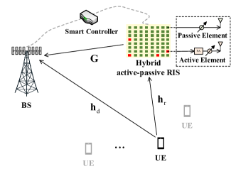
As depicted in Fig. 1, a dynamic HRIS-aided uplink multi-user communication system with single-antenna users and an -antenna BS is considered. The time division multiple access (TDMA) scheme is adopted, where the users are served by the BS over orthogonal time slots. The HRIS consists of elements, where the active elements are equipped with power amplifiers. To reduce the power consumption and hardware complexity, we assume the BS receives data streams from antennas with dedicated RF chains. The antenna selection technique is employed to select out of antennas to explore the spatial diversity.
We denote and as the full channel state information (CSI) associated with receive antennas from the BS to the user and the HRIS, respectively. The channel between the HRIS and the user is . Based on the receive antenna selection, out of or rows are selected to form the or sub-channels, respectively. Denoting as the index matrix for the selected antennas, where , the sub-channels can be represented by and . All channels are assumed to experience quasi-static flat fading and perfectly available using the recent advances in RIS and massive MIMO channel estimation.111Due to the spatial correlation across the large-scale antenna array, the full-dimensional CSI can be recovered from the partial CSI obtained via pilot training [9].
The HRIS comprises active and passive elements, where . The location and the number of active elements are optimized to enhance the system performance. Specifically, we denote as the reflection phase matrix, where denotes the discrete phase shift of the -th element with . is the number of quantization bits. The reflection amplitude matrix of HRIS is denoted as , where represents the amplification factor of -th element. For the active elements, we have when , where denotes the minimum amplification factor and is the index set of all active elements. Otherwise, we have for those passive elements. The mode selection matrix related to is denoted as . For simplicity, we assume all the active elements share one common amplification factor .
With the non-ideal phase shifters of HRIS, the phase error of the -th element can be modeled as , where denotes the uniform distribution [10]. Therefore, the actual phase shift matrix with phase noise is , with denoting the phase noise matrix.
To accurately model the realistic imperfect hardware, the additive HWIs are considered. Specifically, the aggregate residual HWIs for the transceiver can be modeled as the additive Gaussian distortion noise [11]. As such, the actual transmitted signal for the user is expressed as
| (1) |
where represents the transmitted symbol with . denotes the additive distortion noise whose variance is proportional to the transmit power , where characterizes the distortion level.
Then, the uplink received signal at the BS is written as
| (2) |
where denotes the un-distorted received signal and stands for the additive white Gaussian noise (AWGN) whose elements are random variables with zero-mean and unit-variance, i.e., . in represents the amplified noise associated with the active elements, where . stands for the receive distortion noise. We have , whose variance is proportional to the average received power of the individual antennas at the BS. represents the received distortion level and is derived as
| (3a) | ||||
| (3b) | ||||
where with and . denotes the average effective channel between the user and the BS. The equality holds since and .
Assume that the receive beamforming at the BS is , then the estimated symbol is denoted as
| (4) |
with . Therefore, the average MSE can be derived as
| (5) |
with and .
II-B Problem formulation
In this paper, we mainly focus on enhancing the transmission reliability of the considered system in terms of MSE. Specifically, the average MSE is minimized under the total power budget of HRIS by jointly optimizing the receive antenna selection matrix , the mode selection matrix , the reflection phase matrix , and the reflection amplitude matrix . The total power consumption at the HRIS is calculated as . Then, the average MSE minimization problem can be formulated as
| (6a) | ||||
| (6b) | ||||
| (6c) | ||||
| (6d) | ||||
| (6e) | ||||
where (6c) denotes the discrete phase coefficient constraint and (6d) limits the amplification factor of the active elements. Unfortunately, the problem (P1) is intractable and NP-hard due to the integer constraints and tightly coupled variables. In the sequel, we first transform these intractable constraints and then present a penalty-based exact BCD algorithm to obtain a stationary solution.
III Proposed exact BCD algorithm
In this section, we begin by transforming the binary and discrete variables into continuous ones and then propose to optimize these variables with the others fixed alternately.
III-A Problem Transformation
Since the reflection amplitude matrix and the mode selection matrix are tightly coupled, we first define the auxiliary variable as follows
| (9) |
where denotes the common amplification factor for the active elements. Thus, we have and . The power constraint in (6b) can be transformed into . Therefore, we equivalently optimize the common amplification factor and the mode selection vector in the following.
For the receive antenna selection matrix , we define with and . denotes each belongs to a special ordered set of type 1 (SOS1). On the other hand, to efficiently deal with the discrete phase coefficients, we adopt the binary representation for the discrete variable . Defining as , we can rewrite as , where . Each belongs to the SOS1, i.e., . Similar with the receive antenna selection matrix , we further define with .
The binary variables still render the problem intractable and NP-hard. Though the optimal solution can be obtained by the state-of-the-art Gurobi solver embedded with the branch-and-bound (BB) method, the worst-case complexity increases exponentially with the scale of the problem.
To balance the complexity and optimality, we propose a variational reformulation of the binary constraints. Specifically, these constraints can be equivalently transformed into the box non-separable constraints with the following lemma.
Lemma 1.
Assume and define . Assume that , then we have , and .
Proof.
See [12] for detailed proof. ∎
Based on Lemma 1 and introducing the auxiliary variables , the problem (P1) equivalently turns into the following mix-integer optimization problem:
| (10a) | ||||
| (10b) | ||||
| (10c) | ||||
| (10d) | ||||
| (10e) | ||||
| (10f) | ||||
| (10g) | ||||
where and are similarly defined w.r.t. .
To efficiently tackle the equality constraints in (10e), we penalize the complementary error directly by a penalty function. The resultant objective function is defined as
| (11) |
where the penalty term . Thus, the problem (P3) turns into
| (12) |
In the sequel, we alternatively optimize these variables with the remaining ones fixed.
III-B Receive Beamforming
For any given , the linear MMSE detector is the optimal receive beamforming. Thus, the optimal receive beamforming is written as
| (13) |
III-C Amplification Factor
In this subsection, we optimize the common amplification factor for the active elements of the HRIS with the other variables fixed. Since the penalty term is irrelevant to the amplification factor , we first rewrite the objective as utilizing the matrix identity of and . And is defined as
| (14) |
with the auxiliary terms and . is defined as .
Substituting and into , it can be further transformed to as follows:
| (15) |
With the fixed , the problem for optimizing at -th iteration can be formulated as
| (16) |
where the parameters and are computed as
| (17a) | ||||
| (17b) | ||||
| (17c) | ||||
Then we have the following proposition concerning the amplification factor selection:
Proposition 1.
The HRIS should employ passive elements only when the power budget satisfies
| (18) |
with and employ active elements otherwise.
Proof.
The consumed power at the HRIS achieves the minimum when the amplification factor is equal to and the number of active elements equals 1. Thus, the consumed power at the HRIS satisfies . ∎
Then, we consider the non-trivial case with , where the number of active elements . The optimal amplification factor for the unconstrained minimization in problem (P4) can be derived as
| (19) |
Thus, the optimal for problem (P4) can be obtained by comparing and as follows:
| (23) |
Corollary 1.
For the first two cases with and , the power constraint of the active elements is inactive, indicating the power budget at the HRIS is sufficient. The system performance will degrade if the amplification factor is greater than the threshold due to the amplified noise and hardware impairments.
Corollary 2.
The power constraint becomes active in the case of . Thus, the system performance can be further enhanced with a larger power budget.
III-D Auxiliary Variables
For the auxiliary variables , the problem turns into the following individual convex optimization problems:
| (24a) | ||||
| (24b) | ||||
| (24c) | ||||
The optimal closed-form solutions are readily derived as
| (25a) | ||||
| (25b) | ||||
| (25c) | ||||
III-E Selection Variables
In this subsection, we alternatively optimize the dynamic mode selection vector , the receive antenna selection vector and the reflection phase selection vector using the same optimization oracles.
III-E1 Dynamic mode selection
Based on the transformed objective function in (III-C), the dynamic mode selection problem can be equivalently formulated as the following convex quadratic optimization problem with the quadratic and linear constraints:
| s.t. | (26) |
with , and .
III-E2 Receive antenna selection
With the matrix identity of and , the objective can be equivalently transformed as where . and are defined as and . Then, the receive antenna selection optimization problem can be formulated as the following convex optimization problem with the quadratic objective and linear constraints:
| s.t. | (27) |
III-E3 Reflection phase selection
For the reflection phase optimization, we first transform the objective function into a tractable form w.r.t. and then rewrite it using the binary representative variables . We can decouple the variable from the objective function in (10) as , where denotes the constant term w.r.t. . is defined as where and . Recalling and , the reflection phase optimization problem can be equivalently transformed into the following convex optimization problem:
| s.t. | (28) |
where and .
Since the optimization problems (P5–7) are quadratic convex problems subject to linear and quadratic constraints, the global optimal solutions can be efficiently obtained via the standard CVX solvers. The penalty is updated with every iterations to realize a trade-off between the solution accuracy and the computational complexity. Finally, the BCD algorithm converges to a stationary point with a sufficiently large penalty.
IV Simulation
In this section, we conduct numerical simulations to evaluate the performance of the dynamic HRIS-aided communication system. Unless otherwise stated, we set the basic system parameters as follows: , , , , . Under a three-dimensional deployment setup, the BS and the HRIS are deployed at m and m, respectively. The users are randomly distributed in a circle with a radius of m and a center of m. The transmit power for the user is dBm. The noise powers are given by dBm. The channel is assumed to be Rayleigh fading, while the HRIS-related channels and obey Rician fading with the Rician factor being 0.75. For the large-scale fading, the path loss model is considered, where and respectively denote the propagation distance and the path loss exponent. stands for the path loss at the reference distance of 1m and is set as dB. In particular, we set , and for the BS-HRIS channel , the HRIS-user channel and the BS-user channel , respectively. The conventional passive RIS and active RIS schemes are adopted as the benchmarks. Besides, the hybrid RIS with a fixed number of active elements, denoted as “F-HRIS”, is compared to illustrate the superiority of the proposed dynamic HRIS scheme (“D-HRIS”). The non-robust scheme of ignoring the impact of HWIs, represented as “N-HRIS”, is also considered. For a fair comparison, we assume that the total power budgets for different schemes are the same.
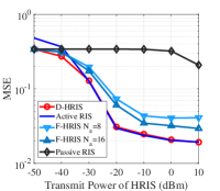
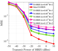
The MSE performance versus the transmit power of HRIS for different schemes are compared in Fig. 2. In Fig. 2 (a), the proposed D-HRIS achieves the same performance as the active RIS in the high transmit power region. In contrast, the D-HRIS performs better than the active RIS in the lower-power regime. It happens because the transmit power is not sufficient to activate all the elements in the active RIS. The performance gap between the D-HRIS and F-HRIS demonstrates the effectiveness of the dynamic configuration for the active elements. Besides, the MSE performance of passive RIS also increases as the transmit power of HRIS increases, since the total power budget increases correspondingly. In Fig. 2 (b), the ideal D-HRIS limits the MSE performance of the HWI-aware systems to an upper bound. The D-HRIS always achieves better performance than the N-HRIS scheme under various setups of HWIs. It showcases the effectiveness of the robust design under imperfect hardware implementations.
V Conclusion
In this paper, we investigated the channel-aware placement of receive antennas at the BS and active/passive elements at the HRIS under the imperfect hardware implementation. The average MSE minimization problem for the dynamic HRIS-aided massive MIMO system was studied by jointly optimizing the receive antenna selection matrix, the reflection phase coefficients, the reflection amplitude matrix, and the mode selection matrix for the active elements. To tackle the non-convexity and intractability of this problem, we proposed a penalty-based exact BCD algorithm to solve these variables alternately. Numerical simulations showed great superiority of the channel-aware configuration for the receive antennas and active/passive elements in the HRIS-aided massive MIMO system as compared to the conventional benchmark schemes.
References
- [1] X. Zhai, Y. Cai, Q. Shi, M. Zhao, G. Y. Li, and B. Champagne, “Joint transceiver design with antenna selection for large-scale MU-MIMO mmwave systems,” IEEE Journal on Selected Areas in Communications, vol. 35, no. 9, pp. 2085–2096, 2017.
- [2] A. F. Molisch, V. V. Ratnam, S. Han, Z. Li, S. L. H. Nguyen, L. Li, and K. Haneda, “Hybrid beamforming for massive MIMO: A survey,” IEEE Communications magazine, vol. 55, no. 9, pp. 134–141, 2017.
- [3] S. Sanayei and A. Nosratinia, “Antenna selection in MIMO systems,” IEEE Communications magazine, vol. 42, no. 10, pp. 68–73, 2004.
- [4] Y. Gao, H. Vinck, and T. Kaiser, “Massive MIMO antenna selection: Switching architectures, capacity bounds, and optimal antenna selection algorithms,” IEEE Transactions on Signal Processing, vol. 66, no. 5, pp. 1346–1360, 2018.
- [5] A. M. Elbir and K. V. Mishra, “Joint antenna selection and hybrid beamformer design using unquantized and quantized deep learning networks,” IEEE Transactions on Wireless Communications, vol. 19, no. 3, pp. 1677–1688, 2019.
- [6] Q. Wu, S. Zhang, B. Zheng, C. You, and R. Zhang, “Intelligent reflecting surface-aided wireless communications: A tutorial,” IEEE Transactions on Communications, vol. 69, no. 5, pp. 3313–3351, 2021.
- [7] Q. Peng, Q. Wu, G. Chen, R. Liu, S. Ma, and W. Chen, “Hybrid active-passive IRS assisted energy-efficient wireless communication,” IEEE Communications Letters, 2023.
- [8] R. P. Sankar and S. P. Chepuri, “Channel-aware placement of active and passive elements in hybrid RIS-assisted MISO systems,” IEEE Wireless Communications Letters, 2023.
- [9] X. Yang, S. Ma, and S. Jin, “Antenna selection for asymmetrical uplink and downlink transceivers in massive MIMO systems,” IEEE Transactions on Wireless Communications, 2023.
- [10] J. Wang, S. Gong, Q. Wu, and S. Ma, “RIS-aided MIMO systems with hardware impairments: Robust beamforming design and analysis,” IEEE Transactions on Wireless Communications, vol. 22, no. 10, pp. 6914–6929, 2023.
- [11] S. Gong, C. Xing, H. Liu, X. Zhao, J. Wang, J. An, and T. Q. Quek, “Hardware-impaired RIS-assisted mmwave hybrid systems: Beamforming design and performance analysis,” IEEE Transactions on Communications, vol. 71, no. 4, pp. 2317–2334, 2023.
- [12] G. Yuan and B. Ghanem, “An exact penalty method for binary optimization based on MPEC formulation,” in Proceedings of the AAAI Conference on Artificial Intelligence, vol. 31, no. 1, 2017.