Hardware Design and Learning-Based Software Architecture of Musculoskeletal Wheeled Robot Musashi-W
for Real-World Applications
Abstract
Various musculoskeletal humanoids have been developed so far. While these humanoids have the advantage of their flexible and redundant bodies that mimic the human body, they are still far from being applied to real-world tasks. One of the reasons for this is the difficulty of bipedal walking in a flexible body. Thus, we developed a musculoskeletal wheeled robot, Musashi-W, by combining a wheeled base and musculoskeletal upper limbs for real-world applications. Also, we constructed its software system by combining static and dynamic body schema learning, reflex control, and visual recognition. We show that the hardware and software of Musashi-W can make the most of the advantages of the musculoskeletal upper limbs, through several tasks of cleaning by human teaching, carrying a heavy object considering muscle addition, and setting a table through dynamic cloth manipulation with variable stiffness.
I INTRODUCTION
Various musculoskeletal humanoids have been developed so far [1, 2, 3, 4]. These humanoids have structures that are characteristic of the human body, such as the spine structure [5], the flexible five-fingered hand [6], and the radioulnar structure of the forearm [7]. In addition, the redundancy of muscles and nonlinear elastic elements connected in series to the muscles allow for variable stiffness control [8]. The redundant muscles also allow for continuous motion in the case of muscle rupture [9] and task-specific muscle addition [10]. While these various studies have been conducted, these humanoids are far from being applied to real-world tasks. One of the reasons for this is the difficulty of bipedal walking in a flexible body. The flexible and complex bodies of musculoskeletal humanoids are difficult to control, and while various learning-based control methods have been proposed [11, 12], none have yet succeeded in walking control. Therefore, real-world applications that take advantage of the muscle redundancy, variable stiffness control, and various biomimetic features of the musculoskeletal structure have not been conducted.
In this study, we develop a musculoskeletal wheeled robot, Musashi-W, which is a combination of musculoskeletal dual arms [4], a mechanum-wheeled base, and a linear motion mechanism (Fig. 1) aiming at a more practical system. It is equipped with musculoskeletal upper limbs that include flexible five-fingered hands, redundant muscles, and nonlinear elastic elements, aimed to be applied to various real-world tasks. In addition, having a mechanum-wheeled base and a linear motion mechanism enables a wide range of stable movements to take advantage of the features of the musculoskeletal upper limbs. As for the software, in order to cope with the flexible and complicated hardware configurations, we constructed a learning system based on body schema learning [12, 13]. Static body schema learning [12] is used for basic motion controls of the musculoskeletal body, and dynamic body schema learning [13] is applied for more dynamic motions involving tools and target objects. In addition, we incorporate reflex controls to prevent the increase of internal force between antagonist muscles when performing a long series of motions [14, 15]. We integrate them with visual recognition and classical controls to realize real-world applications that take advantage of the flexibility and redundancy of the musculoskeletal body.


The contributions of this study are as follows.
-
•
Development of a musculoskeletal platform for real-world applications by integrating flexible and redundant musculoskeletal upper limbs with a wheeled base and a linear motion mechanism.
-
•
Development of a learning-based software system that enables the realization of various movements by the developed complex body.
-
•
Realization of real-world tasks using the developed hardware and software.
The structure of this study is as follows. In Section II, we describe the design of the musculoskeletal dual arms with various biomimetic features, the design of the wheeled base to enable a wide range of motion, and the overall design integrating these components. In Section III, we describe the overall software that integrates static and dynamic body schema learning, reflex control, visual recognition, etc. to operate the developed complex hardware. In Section IV, we describe a cleaning experiment with human teaching, an object carrying experiment considering muscle addition, and a table setting experiment including dynamic cloth manipulation.
II Hardware of Musculoskeletal Wheeled Robot Musashi-W
The hardware overview of the developed musculoskeletal wheeled robot Musashi-W is shown in Fig. 2.
II-A Design of the Musculoskeletal Dual Arms
The detailed design of the musculoskeletal dual arms of Musashi-W is shown in the right figure of Fig. 2. The basic skeletal structure consists of joint modules (B5), generic aluminum frames (B6), and joint attachments (B3). The joint module combines two types of central parts and three types of axial parts to enable various joint structures [4]. It contains joint angle sensors and IMU inside, which can be used as redundant sensors. The skeleton is formed by connecting the joint modules to generic aluminum frames using joint attachments. As muscle actuators, sensor-driver integrated muscle modules (B7) [16] and miniature bone-muscle modules (B8) [7] are installed. The former is a muscle module that integrates a muscle motor, a motor driver, a muscle tension measurement unit, a pulley to wind the muscle, and a temperature sensor, to improve maintainability and reliability. The actuator is a Maxon BLDC motor 90W with 29:1 gear ratio, and 10 actuators are installed for each arm. In addition to the advantages of the former, the latter is a module that can be used as a skeleton by integrating two small motors and filling the space between them with metal. The actuators are Maxon BLDC motors 60W with 128:1 gear ratio, and eight actuators are installed for each forearm (four modules for each forearm). Both actuators can freely change the direction of the muscles depending on the placement of the muscle tension measurement units, and thus, together with muscle relay units (B9), various muscle arrangements can be realized. In addition, these muscle modules can be attached to generic aluminum frames or can be connected to each other by using muscle attachments (B2), making it easy to change the muscle arrangement or add new muscles. Since each muscle contains a nonlinear elastic element (B1), the body structure is flexible and its flexibility can be freely changed [17]. The fingers of the musculoskeletal hand (B4) are composed of machined springs, which provide a highly shock-resistant structure, and nine loadcells are placed on the fingertips and palm to detect contact [6]. The sensors mainly measure joint angle from the joint module, muscle tension from the muscle tension measurement unit, muscle length from the encoder attached to the motor, motor temperature from the temperature sensor, and contact force from the loadcells in the hand.
II-B Design of Wheeled Base
Next, we describe the wheeled base and linear motion mechanism. The basic structure of the body is composed of the same generic aluminum frames as the musculoskeletal dual arms, and new components can be added and connected later. The wheels are four mechanum wheels 203 mm in diameter (A8), which allow the robot to move forward and backward, left and right, and rotate. A linear motion mechanism (A1) is constructed by two linear sliders, a timing belt, and a timing pulley. Musculoskeletal dual arms are connected to the linear motion mechanism, and a constant load spring with a load of 160 N is attached to reduce the load on the motor, so that little force is applied to the actuator when the robot is stationary. A motor (a Maxon BLDC motor 200W with 14:1 gear ratio), a motor driver, and a disc coupling attached to the end of the motor are combined into one motor module (A3), and the wheels and linear motion mechanism are driven by these five identical motor modules. The head is equipped with an RGB-D camera Astra S (A5, Orbbec 3D Technology International, Inc.). The neck is constructed by two servo motors, Dynamixel XM430-350 (ROBOTIS Co., Ltd.) in yaw and pitch axes.
II-C Design of Musculoskeletal Wheeled Robot Musashi-W
The musculoskeletal wheeled robot Musashi-W is a combination of the above musculoskeletal dual arms and the wheeled base. The height is 1.43 m at its maximum extension, and the weight is 55.2 kg including batteries. Musashi-W can carry up to five batteries with 13.2 V and 10000 mAh (A7), two of which can be connected in series to serve as logic power supplies, and three of which can be connected in series to serve as power supplies. PC is Intel NUC (Intel Corp.), and keyboard (A2) and touch-panel display (A6) are installed at the rear of the robot. In the lower part of the wheeled base, Realsense T265 (A2, Intel Corp.) is installed, which can perform visual SLAM. There is also a relay and a wireless emergency stop receiver in the middle, and a Joy-Con (A4) in the upper part.
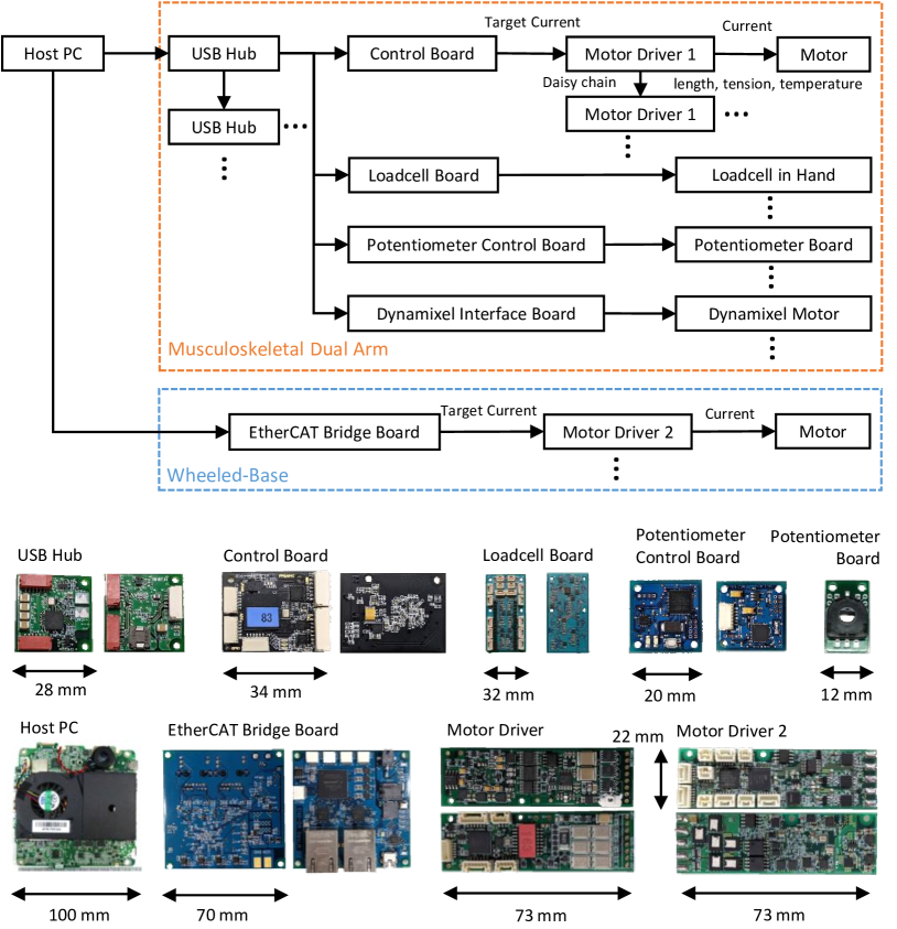
The circuit configuration is shown in Fig. 3. The upper part of the body is based on USB communication, and Motor Driver 1 is connected from USB Hub through Control Board by a daisy chain. Serial communication is used from the Control Board onward. Potentiometer Control Board is placed in the joint module, and is connected to Potentiometer Board for each joint axis. As for the loadcells in the fingers and palm, Loadcell Board is placed on the back of the hand, and multiple loadcells are connected to it. Dynamixel motor on the neck is connected to Dynamixel Interface Board (DXHUB) by a daisy chain. Potentiometer Control Board, Loadcell Board, and Dynamixel Interface Board are connected to USB Hub for serial communication. On the other hand, the lower half of the body is based on Ethernet communication, and Motor Driver 2 is connected to EtherCAT Bridge Board by a daisy chain. Currently, the circuit configuration is different between the musculoskeletal dual arms and wheeled base, but since the size of the motor drivers (Motor Driver 1 and 2) has been unified, it is possible to adapt the entire configuration to the wheeled base side in the future.
III Software of Musculoskeletal Wheeled Robot Musashi-W
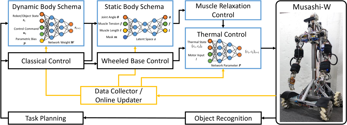
The entire system constructed in this study is shown in Fig. 4. Basic motion control of the musculoskeletal body is performed by static body schema learning, and the dynamic body schema learning is responsible for dynamic motion control considering the information of tools and target objects. For the muscles in upper limbs, muscle relaxation control suppresses the increase in internal muscle force, and learning-based thermal control is performed for each motor. In addition, visual recognition, motion planning, inverse kinematics, and wheel control are integrated.
III-A Static Body Schema Learning
Static body schema learning [12] is a learning mechanism for motion control of musculoskeletal bodies. By learning the relationship between joint angle , muscle tension , and muscle length , the robot is able to calculate the muscle length to achieve the desired joint angle and muscle tension, and to estimate unobservable joint angles. The static body schema can be expressed by the following equation,
| (1) |
where is the static body schema represented by a neural network, and represents a mask variable (). The network input is aggregated into a latent variable , and an output reproduces the input as in AutoEncoder [18]. For , each value can be inferred from the other two values, i.e., , , . In order to represent the mutual relationships in a single network of static body schema, we train it by changing to three types: . The value of represents the presence or absence of a mask for each value of . For example, if , then the network input is , where the corresponding value is masked while training. This static body schema is initially trained from the geometric model, and then it is learned online using the actual robot sensor information. For motion control, a loss function is defined that makes predicted from the static body schema close to the target value and minimizes the muscle tension . The target muscle length minimizing the loss is calculated by iteratively updating through a backpropagation and gradient descent method. Also, variable stiffness control can be realized by adding a constraint to make the body stiffness close to the target value . In addition, though Musashi-W has joint angle sensors, ordinary musculoskeletal humanoids do not have joint angle sensors [3]. In this case, data of for learning can be calculated based on changes in muscle length and visual hand recognition [19]. By learning the static body schema, the robot can estimate from the current and without continuously looking at the hand.
III-B Dynamic Body Schema Learning
Dynamic body schema learning is a mechanism to learn a complex relationship among sensors and actuators related to the body, tools, and target objects, and to control them as intended. The dynamic body schema can be expressed by the following equation,
| (2) |
where represents the state of the robot and target object, represents the control input, represents the dynamic body schema represented by a neural network, and represents the parametric bias [20]. is a learnable input variable from which multiple attractor dynamics can be extracted; by collecting data while changing target objects and environments, information on the resulting changes in dynamics is embedded in . By setting a loss function that makes the prediction of the network close to the actual sensor information, and by updating only while keeping the network weight fixed, the robot can recognize target objects and environments online and obtain dynamic body schema to match [13]. For the motion control, the following calculation is repeated to obtain the optimized time-series control input ,
| (3) | ||||
| (4) | ||||
| (5) |
where is the predicted time-series , is the time-series expansion of , is the loss function, and is the learning rate. In other words, the future is predicted from by , and is optimized by the backpropagation and gradient descent methods to minimize the loss function set for the target task.
III-C Reflex Control
Muscle relaxation control and thermal control work as reflex controls. Muscle relaxation control [15] is a reflex control that suppresses the increase in internal force due to modeling error, which is a problem due to the antagonistic relationship of the musculoskeletal structure. From the joint torque required to maintain the current posture, the necessary muscle tension is calculated by the quadratic programming method below,
| minimize | (6) | |||
| subject to | (7) |
where is the muscle Jacobian, is the minimum muscle tension, and for the calculated . Sorting in ascending order, the muscles are relaxed from the one with the lowest necessary muscle tension to an extent that does not affect the current posture. This method enables the robot to suppress the internal force in the antagonistic relationship and to perform continuous movements. Note that this reflex control cannot be used simultaneously with the variable stiffness control because it suppresses the internal force.
Thermal control [14] is a reflex control that constantly learns the thermal model of the motor and simultaneously controls the temperature of the motor core to keep it within the rated value. We express the motor housing temperature as , which can be measured, and the motor core temperature as , which cannot be directly measured. A two-resistor thermal model of the motor is transformed as follows,
| (8) | |||
| (9) |
where and are functions represented by learnable parameters set by humans, and represents the current to the motor. By setting to a low dimension of 5 while referring to the thermal model of Eq. 8 and Eq. 9, overfitting does not occur compared to a neural network, making it suitable for online learning. The motor core temperature can be estimated using . is updated online from the loss function that matches the prediction and actual measurement for . Also, in the same way as in the dynamic body schema, the maximum current can be calculated from the loss function that makes match the rated value. By limiting the current at this value, the motor core temperature can always be kept within the rated value. These two types of reflex controls enable long-term operation of the robot.
III-D Visual Recognition and Classical Control
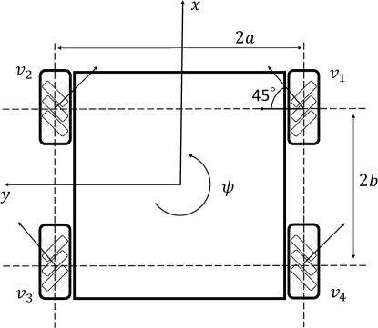
Other than the static body schema, dynamic body schema, and reflex controls described so far, we use general visual recognition, classical control, and task planning. Visual recognition is mainly based on point cloud recognition by color extraction and plane detection, and object recognition by color extraction and template matching. Due to its body flexibility, the musculoskeletal upper limbs do not require impedance control, but can grasp target objects by solving the inverse kinematics for the point cloud of the object, aligning the hand using the static body schema and visual feedback, and then sending a target value to press the hand against the object. Regarding the wheeled base, the velocity of each mechanum wheel is controlled. As shown in Fig. 5, the distance between the wheels in the -direction is , the distance between the wheels in the -direction is , the speed of each wheel is , and the angle in the direction of rotation is . The following equation holds for the wheel velocity and the translational and rotational velocities of the wheeled base:
| (10) | |||
| (11) |
Therefore, for the target velocity , by sending the velocity to each wheel, it is possible to operate the robot in the desired direction. For odometry, it is possible to estimate the current by repeating .
IV Experiments
IV-A Duster Experiment with Human Teaching
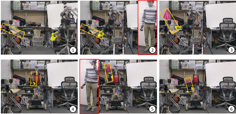
We describe a duster experiment operated by a VR controller which can move the wheeled base, linear motion mechanism, and musculoskeletal upper limbs. All software configurations except for the dynamic body schema are used here. We used HTC VIVE controller (HTC Corp.) and connected all actuators to the controller to construct a teaching system. While moving the robot hands from the position of the controller, the vertical movement of the linear joint and the translation and rotation of the wheeled base can be performed by operating the buttons on the controller. The experiment is shown in Fig. 6. During a period of about two minutes, the robot moves to the desk, picks up the duster, moves to the shelf, and successfully removes dust from a box on the shelf using the duster. We do not need to pay attention to environmental contact due to the flexibility of its body, and the robot can grasp various objects with its flexible five-fingered hand.
IV-B Object Carrying Experiment Considering Muscle Addition
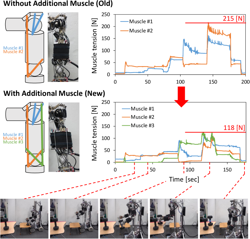
We describe an experiment in which a task is performed by relearning a static body schema, using muscle redundancy, and adding muscles according to the task. All software configurations except the dynamic body schema are used here. As mentioned in Section II-A, muscle modules can be placed in various locations by means of muscle attachments, and we take full advantage of this. Note that a skilled researcher was able to complete the installation of new muscle attachments, muscle modules, wires, and cables in about three minutes. We conduct a task of carrying a heavy object about 6.8 kg in weight, as shown in the lower figures of Fig. 7. In this case, a maximum force of 215N is applied during the operation with the usual muscle arrangement. On the other hand, by adding new muscles, increasing the input and output dimensions of the static body schema, and relearning it [10], the maximum muscle tension is reduced to 118N. In other words, by utilizing the advantages of the musculoskeletal body, the robot is able to perform real-world tasks while changing its body configuration according to the task.
IV-C Table Setting Experiment with Dynamic Cloth Manipulation
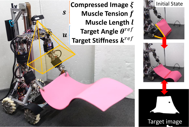
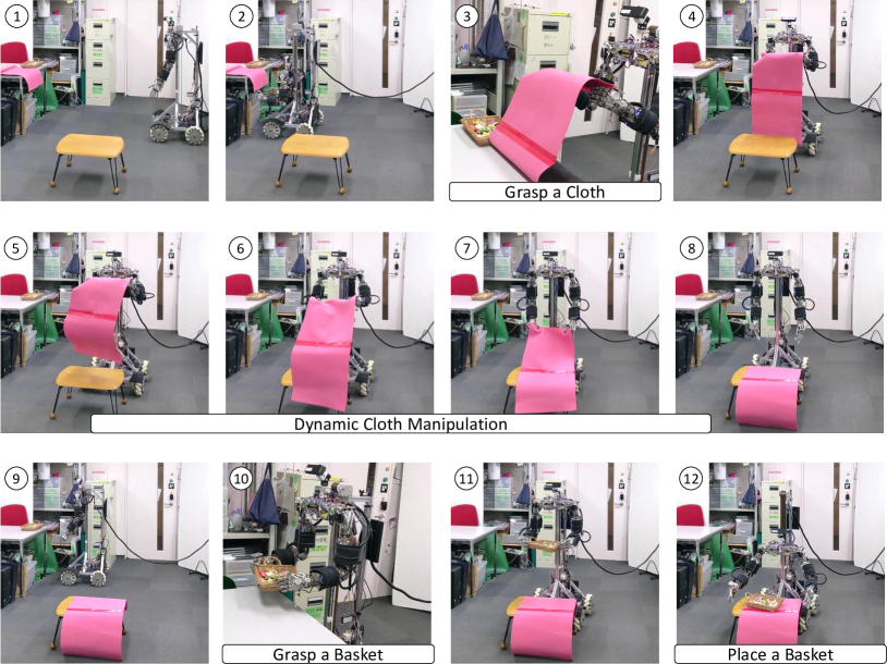
We describe a table setting experiment with dynamic cloth manipulation, which is enabled by learning dynamic body schema as well as utilizing the body’s flexibility and variable stiffness. All software configurations including the dynamic body schema are used here. For the dynamic body schema, as shown in Fig. 8, the cloth image compressed by AutoEncoder, muscle tension , and muscle length are included in , and the target joint angle and target body stiffness are included in . Using the image of an unfolded cloth as the target value, a control input to achieve this image is obtained by optimization calculation [21]. A series of motions for table setting is shown in Fig. 9. The robot moves to the cloth on the desk and extracts the point cloud of the cloth using color extraction. The robot aligns its hand with the static body schema and visual feedback, grasps the cloth, and moves to the table. Using the dynamic body schema, the robot adjusts the transition of the target joint angle and body stiffness to unfold the cloth, and puts the cloth on the table. By manipulating the cloth while changing the body stiffness, the speed of the end effector is improved by about 12% compared to without changing it. The robot moves to the basket of sweets on the desk again, and extracts the point cloud of the basket using plane recognition. The robot aligns its hand with the static body schema and visual feedback, grasps the basket, and moves to the table again. In this case, due to the flexibility of the arm, the robot is able to grasp the basket appropriately just by pressing its hand against it without control. Finally, the robot succeeds in placing the basket on the cloth covering the table. The entire task took about 7 minutes. By combining the musculoskeletal upper limbs with the wheeled base and linear motion mechanism, the robot has successfully performed a series of table setting operations by skillfully using the characteristics of the musculoskeletal structure, which have rarely been applied to real-world tasks.
V CONCLUSION
In this study, we developed a musculoskeletal wheeled robot, Musashi-W, which is a combination of musculoskeletal dual arms and a mechanum-wheeled base, and constructed a learning-based software system for real-world applications by utilizing the advantages of the musculoskeletal body. The musculoskeletal body has a mechanism that can adaptively change its flexibility by using nonlinear elastic elements, and it has the characteristics of redundant muscles and modularity for easy muscle addition. Because of the complexity of the body, it is necessary to learn a static relationship between its sensors and actuators and a dynamic relationship between the body, tools, and target objects. In addition, reflex controls to suppress the increase in internal force caused by redundant muscles, and visual feedback control based on static body schema are important. As a result of these efforts, the musculoskeletal wheeled robot Musashi-W succeeded in carrying heavy objects while considering muscle addition and performing a series of table-setting operations including dynamic cloth manipulation and object grasping. It is possible to solve real-world tasks by taking advantage of the muscle redundancy, body flexibility, and variable stiffness of the upper limbs, and by combining the wheeled base with linear motion mechanism. We believe that the hardware configuration with a flexible body and the online learning-based software configuration proposed in this study will be important elements in performing real-world tasks.
References
- [1] H. G. Marques, M. Jäntsh, S. Wittmeier, O. Holland, C. Alessandro, A. Diamond, M. Lungarella, and R. Knight, “ECCE1: the first of a series of anthropomimetic musculoskeletal upper torsos,” in Proceedings of the 2010 IEEE-RAS International Conference on Humanoid Robots, 2010, pp. 391–396.
- [2] M. Jäntsch, S. Wittmeier, K. Dalamagkidis, A. Panos, F. Volkart, and A. Knoll, “Anthrob - A Printed Anthropomimetic Robot,” in Proceedings of the 2013 IEEE-RAS International Conference on Humanoid Robots, 2013, pp. 342–347.
- [3] Y. Asano, T. Kozuki, S. Ookubo, M. Kawamura, S. Nakashima, T. Katayama, Y. Iori, H. Toshinori, K. Kawaharazuka, S. Makino, Y. Kakiuchi, K. Okada, and M. Inaba, “Human Mimetic Musculoskeletal Humanoid Kengoro toward Real World Physically Interactive Actions,” in Proceedings of the 2016 IEEE-RAS International Conference on Humanoid Robots, 2016, pp. 876–883.
- [4] K. Kawaharazuka, S. Makino, K. Tsuzuki, M. Onitsuka, Y. Nagamatsu, K. Shinjo, T. Makabe, Y. Asano, K. Okada, K. Kawasaki, and M. Inaba, “Component Modularized Design of Musculoskeletal Humanoid Platform Musashi to Investigate Learning Control Systems,” in Proceedings of the 2019 IEEE/RSJ International Conference on Intelligent Robots and Systems, 2019, pp. 7294–7301.
- [5] M. Osada, T. Izawa, J. Urata, Y. Nakanishi, K. Okada, and M. Inaba, “Approach of “planar muscle” suitable for musculoskeletal humanoids, especially for their body trunk with spine having multiple vertebral,” in Proceedings of the 2011 IEEE-RAS International Conference on Humanoid Robots, 2011, pp. 358–363.
- [6] S. Makino, K. Kawaharazuka, M. Kawamura, A. Fujii, T. Makabe, M. Onitsuka, Y. Asano, K. Okada, K. Kawasaki, and M. Inaba, “Five-Fingered Hand with Wide Range of Thumb Using Combination of Machined Springs and Variable Stiffness Joints,” in Proceedings of the 2018 IEEE/RSJ International Conference on Intelligent Robots and Systems, 2018, pp. 4562–4567.
- [7] K. Kawaharazuka, S. Makino, M. Kawamura, Y. Asano, Y. Kakiuchi, K. Okada, and M. Inaba, “Human Mimetic Forearm Design with Radioulnar Joint using Miniature Bone-muscle Modules and its Applications,” in Proceedings of the 2017 IEEE/RSJ International Conference on Intelligent Robots and Systems, 2017, pp. 4956–4962.
- [8] H. Kobayashi, K. Hyodo, and D. Ogane, “On Tendon-Driven Robotic Mechanisms with Redundant Tendons,” The International Journal of Robotics Research, vol. 17, no. 5, pp. 561–571, 1998.
- [9] K. Kawaharazuka, M. Nishiura, Y. Toshimitsu, Y. Omura, Y. Koga, Y. Asano, K. Okada, K. Kawasaki, and M. Inaba, “Robust Continuous Motion Strategy Against Muscle Rupture using Online Learning of Redundant Intersensory Networks for Musculoskeletal Humanoids,” Robotics and Autonomous Systems, vol. 152, pp. 1–14, 2022.
- [10] K. Kawaharazuka, A. Miki, Y. Toshimitsu, K. Okada, and M. Inaba, “Adaptive Body Schema Learning System Considering Additional Muscles for Musculoskeletal Humanoids,” IEEE Robotics and Automation Letters, vol. 7, no. 2, pp. 3459–3466, 2022.
- [11] C. Alessandro, I. Delis, F. Nori, S. Panzeri, and B. Berret, “Muscle synergies in neuroscience and robotics: from input-space to task-space perspectives,” Frontiers in Computational Neuroscience, vol. 7, no. 43, pp. 1–16, 2013.
- [12] K. Kawaharazuka, K. Tsuzuki, M. Onitsuka, Y. Asano, K. Okada, K. Kawasaki, and M. Inaba, “Musculoskeletal AutoEncoder: A Unified Online Acquisition Method of Intersensory Networks for State Estimation, Control, and Simulation of Musculoskeletal Humanoids,” IEEE Robotics and Automation Letters, vol. 5, no. 2, pp. 2411–2418, 2020.
- [13] K. Kawaharazuka, K. Tsuzuki, M. Onitsuka, Y. Asano, K. Okada, K. Kawasaki, and M. Inaba, “Object Recognition, Dynamic Contact Simulation, Detection, and Control of the Flexible Musculoskeletal Hand Using a Recurrent Neural Network With Parametric Bias,” IEEE Robotics and Automation Letters, vol. 5, no. 3, pp. 4580–4587, 2020.
- [14] K. Kawaharazuka, N. Hiraoka, K. Tsuzuki, M. Onitsuka, Y. Asano, K. Okada, K. Kawasaki, and M. Inaba, “Estimation and Control of Motor Core Temperature with Online Learning of Thermal Model Parameters: Application to Musculoskeletal Humanoids,” IEEE Robotics and Automation Letters, vol. 5, no. 3, pp. 4273–4280, 2020.
- [15] K. Kawaharazuka, K. Tsuzuki, M. Onitsuka, Y. Koga, Y. Omura, Y. Asano, K. Okada, K. Kawasaki, and M. Inaba, “Reflex-based Motion Strategy of Musculoskeletal Humanoids under Environmental Contact Using Muscle Relaxation Control,” in Proceedings of the 2019 IEEE-RAS International Conference on Humanoid Robots, 2019, pp. 114–119.
- [16] Y. Asano, T. Kozuki, S. Ookubo, K. Kawasaki, T. Shirai, K. Kimura, K. Okada, and M. Inaba, “A Sensor-driver Integrated Muscle Module with High-tension Measurability and Flexibility for Tendon-driven Robots,” in Proceedings of the 2015 IEEE/RSJ International Conference on Intelligent Robots and Systems, 2015, pp. 5960–5965.
- [17] K. Kawaharazuka, K. Tsuzuki, S. Makino, M. Onitsuka, Y. Asano, K. Okada, K. Kawasaki, and M. Inaba, “Long-time Self-body Image Acquisition and its Application to the Control of Musculoskeletal Structures,” IEEE Robotics and Automation Letters, vol. 4, no. 3, pp. 2965–2972, 2019.
- [18] G. E. Hinton and R. R. Salakhutdinov, “Reducing the Dimensionality of Data with Neural Networks,” Science, vol. 313, no. 5786, pp. 504–507, 2006.
- [19] K. Kawaharazuka, S. Makino, M. Kawamura, Y. Asano, K. Okada, and M. Inaba, “Online Learning of Joint-Muscle Mapping using Vision in Tendon-driven Musculoskeletal Humanoids,” IEEE Robotics and Automation Letters, vol. 3, no. 2, pp. 772–779, 2018.
- [20] J. Tani, “Self-organization of behavioral primitives as multiple attractor dynamics: a robot experiment,” in Proceedings of the 2002 International Joint Conference on Neural Networks, 2002, pp. 489–494.
- [21] K. Kawaharazuka, A. Miki, M. Bando, K. Okada, and M. Inaba, “Dynamic Cloth Manipulation Considering Variable Stiffness and Material Change Using Deep Predictive Model With Parametric Bias,” Frontiers in Neurorobotics, vol. 16, pp. 1–16, 2022.