Non-Primary Channel Access in IEEE 802.11 UHR: Comprehensive Analysis and Evaluation
Abstract
The evolution of the IEEE 802.11 standards marks a significant throughput advancement in wireless access technologies, progressively increasing bandwidth capacities from 20 MHz in the IEEE 802.11a to up to 320 MHz in the latest IEEE 802.11be (Wi-Fi 7). However, the increased bandwidth capacities may not be well exploited due to inefficient bandwidth utilization incorporating primary channel and secondary channels. Particularly, when primary channel is busy, secondary channels (also known as non-primary channels) are prevented from being utilized even if they are idle, thereby wasting the available bandwidth. This paper investigates the fundamentals of the Non-Primary Channel Access (NPCA) protocol that was introduced in IEEE 802.11 Ultra-High Reliability (UHR) group to cope with the above issue. We propose a novel analytical model to assess NPCA protocol performance in terms of the average throughput and delay. Via simulation, we verify that the NPCA network outperforms the legacy network by increasing by at least 50% average throughput while reducing by at least 40% average delay.
Index Terms:
Channel access, 802.11be, throughput, delay.I Introduction
The Institute of Electrical and Electronics Engineers (IEEE) 802.11 standards represent a cornerstone in contemporary wireless access technologies, enjoying widespread application across various domains. Among these, the bandwidth capacity evolved from 20 MHz in the IEEE 802.11a to a maximum of 160 MHz in the 802.11ac/ax standards [1]. The latest iteration, designated as the IEEE 802.11be or Extremely High Throughput (EHT) standard, heralds a significant leap in bandwidth capacity, supporting up to 320 MHz in [2, 3]. This enhancement introduces a paradigm shift in channel utilization strategies. Specifically, the EHT standard facilitates the allocation of secondary channels for stations (STAs) when connected to an access point (AP) supporting the full 320 MHz bandwidth. This approach mitigates the congestion of stations with smaller bandwidth capacities on the primary channel, thereby optimizing the utilization of available bandwidth across both primary and secondary channels.
Despite these advancements, each standard version maintains a primary 20 MHz channel to preserve backward compatibility throughout the standards’ evolutionary trajectory. However, mandating the primary channel in all data transmission processes may impose limitations on system efficiency because the secondary channels are prevented from being utilized when the primary channel is occupied. Despite, the innovative propositions of the EHT standard for secondary channel communications, several critical implementation aspects remain unaddressed, including the methodology for APs to access and transmit data via secondary channels when the primary channel is congested. To further increase the efficiency of the channel access methods, the IEEE 802.11 Ultra-High Reliability (UHR) group further proposes the Non-Primary Channel Access (NPCA) to take advantage of the dynamic usage of non-Primary channels [4].
The throughput determined by 802.11 standard channel access has been widely investigated in the existing works [5, 6, 7, 8, 9, 10, 11, 12, 13, 14]. Particularly, Bianchi’s IEEE 802.11 DCF network model in [6] has been broadly used, in which it sets up a two-dimensional Markov chain for an assumably saturated network where the backoff action of every node is established. It is a simple yet strong model for analyzing the throughput performance of the Base Station Subsystem (BSS). Bianchi’s model was further extended and improved in [7, 8, 9]. Based on Bianchi’s model, the delay analysis of the network was also proposed in [11, 12]. In next generation IEEE 11.be Wi-Fi standard, the performance of the model was further analyzed in [15, 16], where advancements such as bandwidth up to 320 MHz, Multi-Link Operation (MLO), multi-band/multi-channel aggregation and operation improve the throughput and limit delay in the network. However, the performance analysis of the NPCA protocol proposed by the UHR group is still in demand for the standard designer and users to realize the performance gain. Thus we propose a new analytical model and simulation structure based on the latest NPCA proposals to demonstrate the possibility of achieving better performance goals with NPCA protocol. The main contribution of this paper can be summarized below:
-
•
We propose a new analytical model to analyze the system performance of the NPCA based on the underlying discussion of the IEEE 802.11 UHR group.
-
•
We analyze the performance gains based on the different scenarios. The simulation results are aligned with the analytical models.
-
•
We evaluate the performance of the proposed access methodology under various scenarios and conduct the simulations to evaluate the fairness coexistence with legacy devices.
The rest of this paper is organized as follows. Section II introduces the NPCA mechanism. The proposed model in terms of the average throughput and delay in the NPCA network is presented in Section III. In Section IV, we conduct simulations to validate our proposed model. Finally, section V concludes this paper.
II System Architecture
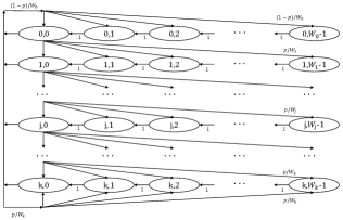
Wireless devices that follow the IEEE 802.11 standards communicate over channels using a protocol, known as Carrier Sense Multiple Access with Collision Avoidance (CSMA/CA). Suppose a device wants to occupy its primary channel. It waits until the channel is sensed idle for a distributed inter-frame space (DIFS), followed by a backoff process. As Fig. 1 shows, the backoff counter value is initialized by uniformly choosing an integer from the range []. Then, it is decremented by one at the end of each idle slot. Note that the backoff counter will be frozen when a packet transmission is detected on the channel and will be reactivated until the channel is sensed idle again for a DIFS period. The device occupies its primary channel and starts transmission when its backoff counter reaches zero. The contention window size is doubled after each unsuccessful transmission, up to a maximum of unsuccessful transmissions.
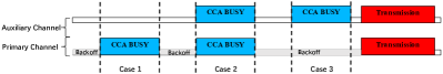
Traditionally, as is shown in Fig. 2(a), devices are allowed to combine the primary channel and secondary channels for larger bandwidth transmission. However, this mechanism only works when the primary channel is idle, which results in bandwidth underutilization. The NPCA model is thereby used to alleviate such inefficiency. As is depicted in Fig. 2(b), devices are allowed to check and switch to other available channels when the primary one is busy. These secondary channels are then used to continue the backoff process and transmit data. After the transmission, devices can switch back to the primary channel if it becomes idle. This approach helps to improve the overall throughput by making sure that available channels are utilized effectively.

III System model
Consider a scenario in a Base Station Set (BSS) where nodes are vying for a chance to transmit. We delve into the throughput analysis of this setting, primarily focusing on a single channel. Following Bianchi’s model [6], the throughput analyzed for single channel network, denoted as , is a key performance metric. The computation of begins with determining , which is the probability of at least one node transmitting in a given slot time:
| (1) |
where represents the likelihood of a station deciding to transmit during a random slot.
Denote as the probability of a successful transmission on the channel, which is given by
| (2) |
which balances the chances of transmission against the odds of success.
Next, we denote as the average time the channel appears busy due to a successful transmission and as the average time it’s busy during a collision. They are given by
| (3) | ||||
| (4) |
where is the PHY header, and is the propagation delay (typically 0.1 ). SIFS, DIFS, and EIFS (equal to ) are time intervals used for processing and responding to frames.
As a result, the average throughput, is expressed as
| (5) |
where represents the duration of an empty slot time, and is the average packet payload size.
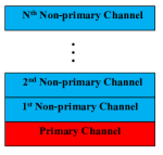
We further extend the analytical throughput model from the single channel to multiple channels, based on the throughput in Eq. (5). As Fig. 3 shows, we consider a multi-channel scenario that includes one primary channel and non-primary channels. For the primary channel, the probability that it is sensed idle each time is . For non-primary channels, the probability that the th () channel is sensed idle is .
We first analyze the throughput of the legacy network for comparison. In a legacy network, non-primary channels are utilized only when the primary channel is idle and the device is ready to send packets. That is, If () channels are enabled to send packets simultaneously, the primary channel and the channels from the to the must be idle, while the channel is busy. Under this scenario, the throughput for channels, denoted as , is given by
| (6) |
where represents the single-channel throughput as calculated in Bianchi’s model. When considering the scenario where all the channels (a total of ) are sending packets, the throughput, , is formulated as
| (7) |
By considering all these scenarios, we obtain the throughput in the legacy network, , as
| (8) |
where denotes the idle probability of the non-primary channel. For further analysis, we define the function as
| (9) |
where and both and start from . This function represents the throughput coefficient assuming that the non-primary channel is the second priority channel, meaning all channels with a higher priority are busy. For instance, if , the non-primary channel is considered the second highest priority at that time, and in this case, .
We then analyze the throughput of the NPCA network. We still consider the throughput aggregated across individual channels. First, the throughput on the primary channel, denoted as , is given by
| (10) |
which implies . When the primary channel is busy, the throughput contributed by other BSSs on the primary channel, , is calculated with the idle probability as
| (11) |
Since the probability that the non-primary channel is idle equals , the corresponding throughput should be
| (12) |
which also indicates . Thus, the overall throughput when the non-primary channel is selected as the highest priority channel, , is
| (13) |
Similarly, if we define the as the throughput on th non-primary channel, we can infer that
| (14) | ||||
Note that for , , indicating that there is no non-primary channel, so the coefficient is 1, considering only the scenario where the non-primary channel is transmitting. Taking all these scenarios into account, the throughput in NPCA network, , is derived as
| (15) | ||||
Remark 1.
Meanwhile, we also analyze the access delay for the NPCA network. The access delay is defined as the time interval from the instant that a data packet is ready for transmission by a device to the instant that it begins transmission on the network medium. Drawing on the research by Taka Sakurai et al.[12], we find that with a large maximum contention window, the expected access delay can be expressed as
| (16) | ||||
where denotes the slot duration, and , a random variable (r.v.), represents the channel occupancy during a successful transmission by the tagged station. is a r.v. denoting the channel occupancy during a collision involving the tagged station, whereas and are r.v.s representing the channel occupancy for the corresponding phenomena but excluding the tagged station. Specifically,
| (17) | ||||
IV Simulation
This section details our experiments on network performance, specifically focusing on throughput and packet delay in NPCA BSS and Legacy BSS systems. Initially, we examine a two-channel BSS under varying channel occupancy rates for both NPCA and legacy networks. We then explore a scenario where two BSS systems compete for transmission, analyzing their throughput and access delay. This helps us understand the interaction between NPCA and legacy networks when combined. Finally, we assess the delay in a two-BSS system across different network types. Table I outlines the simulation parameters and channel transmission settings.
| Parameters | Value |
|---|---|
| Simulation Time (s) | 30 |
| Number of Channels | 2 |
| Primary Channel | Channel 1 |
| Channel Bandwidth (MHz) | 20 |
| Channel Utilization | 1 |
| Packet Size (Bytes) | 1500 |
| MCS | 7 |
| CW Min, | 16 |
| CW Max, | 1024 |
| Slot (us) | 9 |
| SIFS (us) | 16 |
| DIFS (us) | SIFS + 2 Slot |
IV-A Single BSS on Different Channel Occupancy Rate
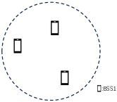
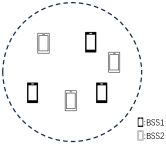
We first explore how NPCA’s throughput compares to the legacy network, particularly when the primary channel is highly occupied. We simulate a scenario where all stations within a single BSS can detect each other, as is shown in Fig. 4(a). The legacy BSS, based on the Bianchi model, and NPCA model are simulated under varying primary channel occupancies. In this case, each BSS contains 10 stations, with Channel 1 designated as the primary channel. We simulate low occupancy (Idle rate: ) on Channel 2 and very high occupancy (Idle rate: ) on the primary channel (Channel 1) to observe the impact on network throughput. As is depicted in Fig. 5, where it illustrates the throughput of 40 MHz networks when the Non-Primary Channel is relatively idle () while Primary Channel is busy (), that the legacy network struggles with high occupancy on the primary channel, leading to more collisions and waiting periods due to Bianchi’s rule. Conversely, NPCA demonstrates significantly better throughput, particularly when the primary channel is busy. NPCA achieves this by switching to the secondary channel (Channel 2) when it senses congestion on the primary channel. The busier the primary channel, the more beneficial it is to switch to Channel 2, showcasing NPCA’s advantage in utilizing secondary channels to enhance network quality.

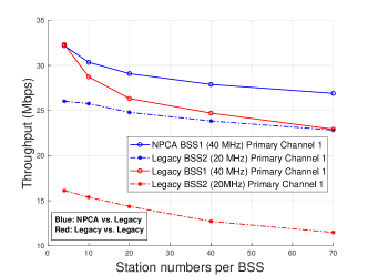
IV-B Two-BSS System
We conducted two simulations for this model, involving one 40 MHz (two-channel) and one 20 MHz (single-channel) BSS within the same sensing area. As is depicted in Fig. 4(b), each BSS has an equal number of stations, and all the nodes can sense each other. In the first scenario, both BSS systems are legacy networks. The simulated throughput in Fig. 6 matches our analytical model, and we observe that the throughput of the 40 MHz BSS (BSS1) is twice as much as the throughput of 20 MHz BSS (BSS2), attributed to its dual-channel capability allowing two packets to be transmitted simultaneously. As the number of stations increases, the likelihood of collisions also rises, leading to reduced throughput following Bianchi’s rule. In the second scenario, BSS1 (40MHz) becomes an NPCA network while BSS2 (20MHz) remains a legacy network. Intriguingly, as is shown in Fig. 6, it indicates the comparison of two-BSS system’s performance in two scenarios. The blue line shows NPCA with Legacy BSS while the red one reveals two Legacy BSSs. We can see that NPCA’s throughput surpasses that of the legacy network under equal station counts. Additionally, when paired with the NPCA network, the legacy network’s throughput also improves significantly. This enhancement occurs because BSS1, upon detecting the transmission from BSS2, opts for the secondary channel for backoff or transmission, thus increasing its transmission probability. Meanwhile, BSS2 gets a better chance to transmit on Channel 1.
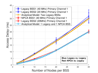
IV-C Access Delay Analysis
As is illustrated in Fig. 7, we expand upon the two-BSS model simulation to investigate its access delay. Access delay is the total time a data packet takes to move from its starting point to its destination. This includes all types of delays, such as those caused by the data waiting in line (queuing), the time it takes to process the data at each stop along the way (processing), the physical time it takes to move the data (propagation), and the time to actually send the data (transmission delays). Understanding access delay is key for evaluating how well different network protocols and devices perform under a variety of conditions. This knowledge helps in designing and optimizing networks to ensure they deliver data quickly and reliably, which is particularly important for applications that need fast responses.
In our simulations, we observed that having more nodes in the BSS tends to increase the likelihood of collisions. This means data packets have to be sent again (retransmitted) and wait longer to get through. However, the NPCA model helps reduce access delay, making the network not only quicker but also more consistent in its performance. This stability is crucial for a network’s efficiency. The reason behind this improvement is twofold. First, NPCA is better at managing how channels are used. It can move transmissions to other channels when necessary, making sure the network keeps running smoothly without bottlenecks. Second, it reduces the number of collisions, which means data flows more freely without as many interruptions. This leads to a network that’s not only faster but also more reliable, with less variation in delay times, enhancing overall network performance.
V Conclusion
This paper presented a comprehensive study on the NPCA protocol proposed by the IEEE 802.11 UHR group. We developed a novel analytical model for the NPCA network, which was further validated by the simulation. We showed that the NPCA network outperforms the legacy network in terms of throughput by optimizing the utilization of available bandwidth across primary and secondary channels, especially under the busy primary channel. Meanwhile, we also evaluated the performance of the NPCA network in coexistence with the legacy network, revealing that the NPCA also impacts the legacy network by not only significantly improving the throughput but also maintaining a lower level of access delay. Our contribution to the ongoing discussions within the IEEE 802.11 UHR group provides analytical insights regarding the NPCA implementation in the upcoming 802.11be.
References
- [1] A. Masiukiewicz, “Throughput comparison between the new hew 802.11 ax standard and 802.11 n/ac standards in selected distance windows,” International Journal of Electronics and Telecommunications, vol. 65, no. 1, pp. 79–84, 2019.
- [2] D. López-Pérez, A. Garcia-Rodriguez, L. Galati-Giordano, M. Kasslin, and K. Doppler, “IEEE 802.11 be extremely high throughput: The next generation of wi-fi technology beyond 802.11 ax,” IEEE Communications Magazine, vol. 57, no. 9, pp. 113–119, 2019.
- [3] R. P. F. Hoefel, “IEEE 802.11 be: Throughput and reliability enhancements for next generation wi-fi networks,” in 2020 IEEE 31st Annual International Symposium on Personal, Indoor and Mobile Radio Communications. IEEE, 2020, pp. 1–7.
- [4] IEEE 802.11 WG, “Non-primary channel access,” IEEE 802.11 Meeting, 2023, doc.: IEEE 802.11-23/0797r0.
- [5] H. Yin, S. Roy, and S. Jin, “IEEE WLANs in 5 vs 6 GHz: A comparative study,” in Proceedings of the 2022 Workshop on ns-3, 2022, pp. 25–32.
- [6] G. Bianchi, “Performance analysis of the IEEE 802.11 distributed coordination function,” IEEE Journal on Selected Areas in Communications, vol. 18, no. 3, pp. 535–547, Mar. 2000.
- [7] H. Wu, Y. Peng, K. Long, S. Cheng, and J. Ma, “Performance of reliable transport protocol over IEEE 802.11 wireless lan: analysis and enhancement,” in Proceedings.Twenty-First Annual Joint Conference of the IEEE Computer and Communications Societies, vol. 2, 2002, pp. 599–607 vol.2.
- [8] C. H. Foh and J. Tantra, “Comments on IEEE 802.11 saturation throughput analysis with freezing of backoff counters,” IEEE Communications Letters, vol. 9, no. 2, pp. 130–132, 2005.
- [9] I. Tinnirello, G. Bianchi, and Y. Xiao, “Refinements on IEEE 802.11 distributed coordination function modeling approaches,” IEEE Transactions on Vehicular Technology, vol. 59, no. 3, pp. 1055–1067, 2009.
- [10] H. Yin, P. Liu, K. Liu, L. Cao, L. Zhang, Y. Gao, and X. Hei, “ns3-ai: Fostering artificial intelligence algorithms for networking research,” in Proceedings of the 2020 Workshop on ns-3, 2020, pp. 57–64.
- [11] E. Ziouva and T. Antonakopoulos, “CSMA/CA performance under high traffic conditions: throughput and delay analysis,” Computer communications, vol. 25, no. 3, pp. 313–321, 2002.
- [12] T. Sakurai and H. L. Vu, “MAC access delay of IEEE 802.11 DCF,” IEEE Transactions on Wireless Communications, vol. 6, no. 5, pp. 1702–1710, 2007.
- [13] X. Gao, Y. Sun, D. Wei, X. Xu, H. Chen, H. Yin, and S. Cui, “Learning for semantic knowledge base-guided online feature transmission in dynamic channels,” arXiv preprint arXiv:2311.18316, 2023.
- [14] L. Cao, H. Yin, J. Hu, and L. Zhang, “Performance analysis and improvement on DSRC application for V2V communication,” in 2020 IEEE 92nd Vehicular Technology Conference (VTC2020-Fall). IEEE, 2020, pp. 1–6.
- [15] D. Lopez-Perez, A. Garcia-Rodriguez, L. Galati-Giordano, M. Kasslin, and K. Doppler, “IEEE 802.11be extremely high throughput: The next generation of Wi-Fi technology beyond 802.11ax,” IEEE Communications Magazine, vol. 57, no. 9, pp. 113–119, Sep. 2019.
- [16] L. Zhang, H. Yin, S. Roy, L. Cao, X. Gao, and V. Sathya, “IEEE 802.11 be network throughput optimization with multi-link operation and AP coordination,” arXiv preprint arXiv:2312.00345, 2023.