Computational Seismic Fracture Synthesis of Tidal Barrage using Enhanced Isotropic Plasticity Damage Mechanics and Coupled Lagrangian-Eulerian Multiphase Interaction
Abstract
Mega-engineered hydraulic structures like dams and barrages are critically sensitive to strong ground motion if constructed within the vicinity of triggered fault lines. Collapse post excessive deformation leads to severe environmental impact. In this study, fracture corresponding to the response of a concrete tidal barrage to strong ground motion is analyzed along with behavioral effects due to reservoir-barrage dynamic interaction. An enhanced version of the plasticity damage mechanical model, which includes effects due to degradation of elastic stiffness of concrete as well as restoration of fracture energy losses is assigned as material behavior. The fluid-structure interaction is solved using an idealized Lagrangian-Eulerian formulation. The proposed improvised numerical formulations are validated against benchmark simulations performed on the Koyna dam situated in Maharashtra, India and the results captured are upto 94% accurate. Finite element simulation of a tidal barrage is performed using a computationally stable mesh with global grid to length ratio of 4.2. The yield surface captured is elliptical in nature and fracture is observed to be propagating from bottom of gate housing covering upto four nodal integration points.
keywords:
Enhanced plasticity damage mechanics , fluid-structure interaction , finite element coupling , Lax-Wendroff scheme , time marching algorithm , crack propagation1 The Prelude
Tidal barrages are rare concrete spillway structures located within the structural enclosure of a dam or any hydraulic structure used to control the discharge of excess reservoir water onto the downstream end. Generally, spillways have a reservoir on the upstream and a riverbed on the downstream side whereas tidal barrages are an exception for having tidal variation from the gulf or ocean on the downstream side (Murali and Sundar, 2017). The Gulf of Khambhat Development Project also known as the Kalpasar project is one of the first mega projects in India with an aim to construct the world’s largest freshwater reservoir dam within the gulf of Khambhat to address the rising drought and freshwater scarcity scenarios in the coastal vicinity of Gujarat, having a reservoir on the upstream end and tidal variations on the downstream end (Subba Rao, 2011). The 60-km long earthen masonry dam connects Aladar on the eastern side and Bhavnagar on the western side of the gulf (Sitharam, 2017). Mega-engineered structures are critically sensitive to strong ground motions and undergo excessive deformation if located within the vicinity of the triggered fault lines. Strong ground motions are the strongest shaking that occurs within an approximate radial epicentral distance of 50 km from the sensitive fault lines (Hanks and McGuire, 1981). The response of a relatively rigid structure to strong ground motion is quite abrupt and more critical than any relatively flexible structure. The concrete tidal barrage enclosed within a long stretch of earthen masonry dam is analogous to a system consisting of rigid links connecting two or more identical flexible elements. Sensitivity to seismicity and resulting behavioral aspects of concrete structures, majorly mega-structures like dams and spillways, have been the subject of extensive research during the last ten to fifteen years concerning the safety of such structures. After the historic 1967 Koynanagar earthquake in India with a magnitude of 6.67 Richter scale creating havoc and misery to the daily livelihood in the vicinity of the dam, engineers and scientists found a reason to address the response of dams to seismic forces. It was then, that people started to rethink the environmental impact it would cause due to the catastrophic failure of such mega structures. Non-linear analysis of the Koyna dam was carried out by Pal (1976) for the very first time. Chopra and Chakrabarti (1973) studied the crack paths of the Koyna dam using the linear elastic method of analysis. The majority of the concrete tidal barrages or spillways in the operational phase have internal zones of micro-cracks present. These cracked zones are formed due to seismic impact, thermal expansion and contraction, irregular foundation settlements and material properties of the hardened concrete (Bazant, 1985).
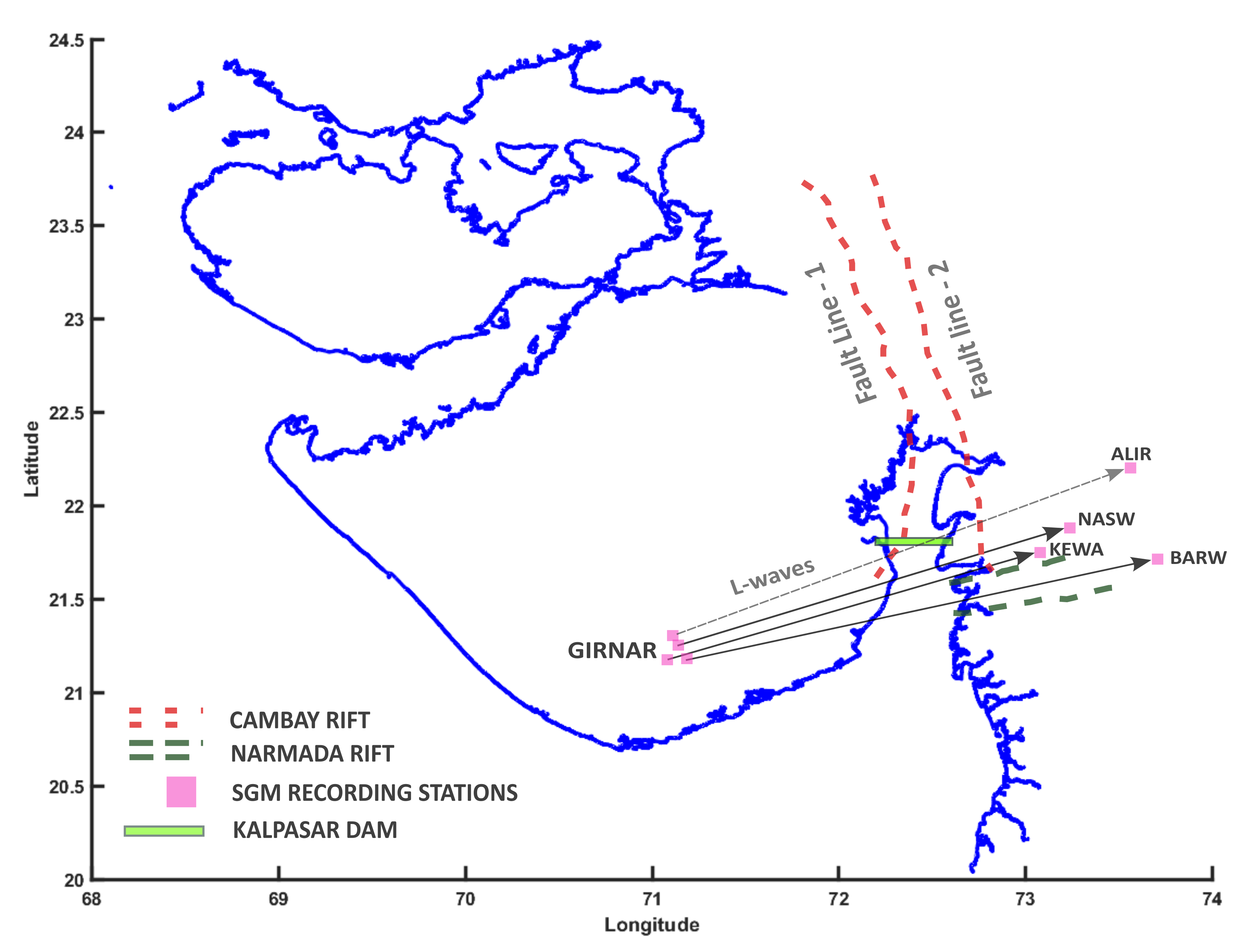
The formation of cracks and micro-cracks due to the structure’s response to seismic excitation is catastrophic in nature. Concrete spillways are designed to resist the nominal static earthquake excitation where the material behavior is restricted within the elastic region of the stress-strain curve of the concrete. When the spillway is in the dynamic excitation phase due to maximum credible earthquake forces, the elastic stiffness of the concrete starts degrading slowly and the material enters the strain-softening region of the stress-strain curve. Hall (1988) mentioned in his study that linear analysis of dynamically excited spillway due to strong ground motion can produce critical tensile stresses in the structure exceeding the tensile strength of the structure itself. Quantitative research has been carried out over the last two decades addressing the behavior of fractures and cracks in the concrete due to non-linear responses. The major drawback of the classical theory of linear elastic fracture mechanics is that the non-linear material fracture process, which is significantly large for concrete dams and spillways is neglected. Classical smeared crack analysis from the continuum fracture mechanics theory is less reliable due to the mesh-insensitivity (Cervera and Chiumenti, 2006). The non-linear material damage configuration of the spillway in the dynamically excited phase can be realistically simulated using computational coupling of damage mechanics and plasticity theory. Damage mechanics is rather an ideology to visualize the material behavior of concrete during the degradation of the elastic stiffness. Mridha and Maity (2014) investigated the nonlinear crack propagation in the Koyna dam using the plasticity-damage tension softening model and it was observed that compressive damage was less critical than tensile damage. The state of Gujarat, situated along the western coastal region of the Indian subcontinent is one of the most seismic sensitive intercontinental peninsular regions of the world, susceptible to strong ground motion excitation and critical hazards (Choudhury et al., 2018). Dating back to January 26th, 2001, the world witnessed one of the most damaging earthquakes from time immemorial originating at Bhuj, Gulf of Kachchh, India with a magnitude of Mw-7.7 on the Richter scale. The majority of the strong ground motions in Gujarat are due to its positional constrain directly on top of the Himalayan collision zone where the Indo-Australian tectonic plate and the Eurasian tectonic plate undergo wedge slipping causing sensitive fault lines at the point of slip (Ni and Barazangi, 1984). Subsequent fault lines form a rift in between, two such rifts, the Cambay and the Narmada rift is formed below the gulf of the Khambhat region as shown in Fig. 1. The Kalpasar dam as shown in Fig. 1 is critically sensitive owing to its positional constrain. The eastern fault of the Cambay rift as well as the historic love wave path tracing from station GIRNAR to station ALIR falls right underneath the kalpasar dam henceforth increasing its vulnerability to the seismic forces (Chopra et al., 2008).
2 Enhanced Isotropic plasticity damage mechanical model for material fracture simulation
The plasticity-damage model is an extensive continuum-based material mechanical process that pragmatically simulates the non-linear behavior of the material post dynamic excitation. The novelty of this theory is that it takes into consideration an associative yield surface having non-associative flow rule, pressure reactivity, flow path reactivity, and is sensitive to both strain hardening and strain softening (Hafezolghorani et al., 2018). The parameter ”damage” exclusively defines the non-linear degradation of a material’s elastic stiffness after the formation of micro-cracks (Grassl et al., 2013).
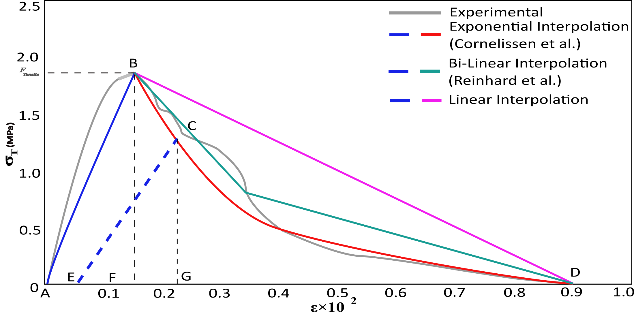
These micro-cracks as already discussed in the prelude are often present as internal deformations within the structural enclosure. Mammoth-scaled Structures like spillways and tidal barrages constructed with quasi-brittle materials are mostly damaged by the formation and propagation of tensile cracks. Split-tensile test using wedge splitting technique was performed by Brühwiler and Wittmann (1990) on a cylindrical specimens of quasi-brittle material to obtain an experimental stress-strain curve having irregular tension hardening and softening phases as shown in Fig. 2. The region where the material undergoes strain hardening and tensile stiffness softening, split-tensile test, or rather uni-axial tension test fails to bring out precise results owing to extremely high non-linear deformation rate of the initially present internal micro-crack (Petrov et al., 2012). In Fig. 2, the curve length from point A to point B is interpolated from erroneous experimental results and represents the elastic region of tensile response. At point B, the material cracks. Post failure the material undergoes strain-softening from point B to C and elastic stiffness degradation from point C to D. At point D, the material is completely fractured. Line EC denotes the unloading-reloading part of the process having slope , where is the elastic stiffness degradation of the tension curve and is the elastic modulus. The distance between points A and E is the region of plastic hardening and denoted as and the distance between points A and F is the region of plastic cracking denoted by . The slope of line in Fig. 2 is denoted by and for line it is .
2.1 The coupled damage-plasticity formulation
The directional invariant elasticity and the tensile plasticity are used to formulate the total strain tensor equation (Voyiadjis et al., 2008).
| (1) |
| (2) |
| (3) |
The nominal stress tensor as given in Eqn. 2 can be expressed using a scalar damage variable as follows:
| (4) |
| (5) |
Since, the effect of compressive damage in mega-structures like spillways, tidal barrages and dams are less critical in nature, the compressive stress tensor becomes negligible and (Tekie and Ellingwood, 2003). Therefore rearranging and modifying Eqn. 5 we get-
| (6) |
| (7) |
| (8) |
Where, is a scalar isotropic tensile damage parameter and is the uniaxial tensile stress capacity of the quasi-brittle material at failure stage. Plastic hardening variables with directional invariance were used to control the formation of the yield surface. From the uniaxial tensile test curve as given in Fig. 2 plastic hardening strain was formulated as follows:
| (9) |
Neglecting flow in the elastic region of the stress-strain curve given in LABEL:fig:3 and neglecting compressive damage, Eqn. 9 can be formulated as:
| (10) |
is the governing flow rule in the plastic deformation zone of the yield surface and is given as:
| (11) |
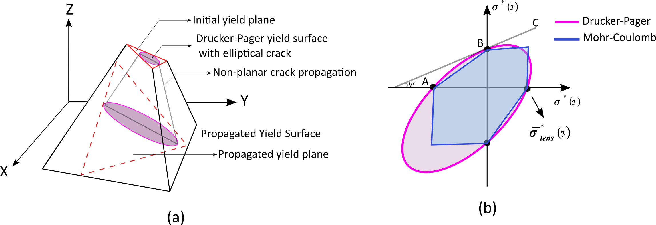
where, , , is the flow eccentricity and is the dilation angle. In this study, a fully enriched unstructured tetrahedral element is considered for fracture analysis and a near-elliptical crack is inserted in the yield surface to study the fracture propagation patterns as shown in Fig. 3. This near-elliptical yield surface is governed by Drucker-Pager’s failure theory (Chang and Pan, 1997). A best fit uniaxial hyperbolic curve from Mohr-Coulomb and Drucker-Pager profiles is formulated as follows:
| (12) |
Where, , and .
From Eqn. 8 and Eqn. 10, the uniaxial tensile behavior of quasi-brittle material is derived taking into consideration that in tension, failure occurs through crack propagation in the plastic hardening zone.
The equation is formulated as follows:
| (13) |
For quasi-brittle materials like concrete which are devoid of any kind of reinforcements, the response to uniaxial tensile behavior given in Eqn. 13 is modified by utilizing a stress-displacement curve instead of a stress-strain curve (Yazdani and Schreyer, 1990). The equation can be written as follows:
| (14) |
2.2 An enhanced tensile damage-plasticity parameter
As evident from Fig. 2, there is a finite curve shift in the tension softening zone of the uniaxial stress-strain tension curve proposed by Reinhard and Cornelissen from the actual experimental curve. This shift is due to losses in fracture energy criteria. Even an infinitesimally small fracture energy loss can result in erroneous values of the elastic stiffness degradation parameter or the tensile damage parameter leading to formation of coarse fracture paths. This study proposes an enhanced version of the plasticity damage mechanical model by restoring the fracture energy losses back to the computational grid in form of correction factor multiplied with the term in Eqn. 8 as follows-
| (15) |
| (16) |
| (17) |
| (18) |
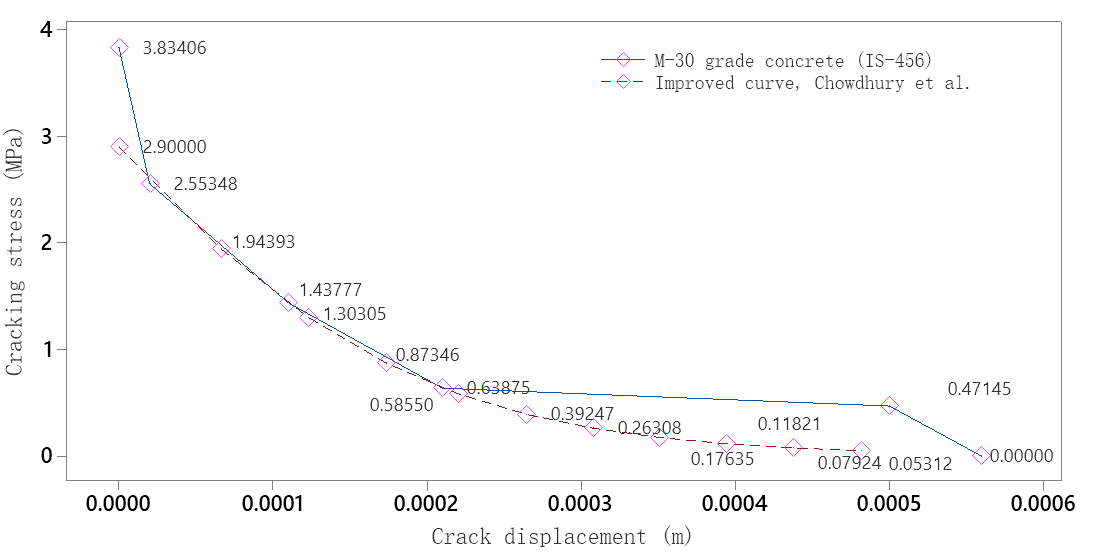
After computation of Eqn. 18 for ranging from 0.585 MPa to 1.944 MPa, where the curve shift is critical, the fracture energy loss coefficient comes out to be near approximated averaged value of 0.08264.
3 Computation of coupled multiphase dynamic fluid-structure interaction (CMDFSI)
A large volumetric mass of freshwater gets confined within the boundary of a dam known as a reservoir and interacts critically with the dam and its components like spillways, and tidal barrages during dynamic excitation due to strong ground motion. The kalpasar dam takes an average inflow of 8000 to 10,000 million cubic meters of water from the major perennial rivers like Sabarmati, Narmada, Mahi, Tapi and Dhadhar (Kolathayar et al., 2019). The inflow of such a huge volumetric quantity results in sloshing of the free water surface. Sloshing can be very well formulated numerically by using the Lagrangian method but due to the combined effects from dynamic excitation of the reservoir bottom as well as the fluid-structure interaction zone, mesh extortions are huge and the Lagrangian method becomes computationally unstable thus an idealized coupled Lagrangian-Eulerian numerical formulation needs to be implemented (Hirt et al., 1970).
3.1 Idealized Lagrangian-Eulerian (ILE) formulation
The generalized form of the famous Navier-Stokes equation with respect to mass, momentum and energy conservation can be written using the divergence theorem as-
| (19) |
| (20) |
| (21) |
Where, , is the velocity of free surface of water in the x-direction of flow, is the mass-density of water at ideal condition and is the energy released or stored. Eqn. 19, Eqn. 20 and Eqn. 21 can be written in a generalized form as-
| (22) |
Where, is any one fluid property of concern like mass, density, energy etc and is the flux of the remaining fluid properties (Chorin, 1968).
The flux through any flow grid inside the domain of computation can be written as-
| (23) |
Now, the Lagrangian formulation is coupled with Eqn. 23 to form the so-called Idealized Lagrangian-Eulerian formulation or the ILE-formulation and can be written as-
| (24) |
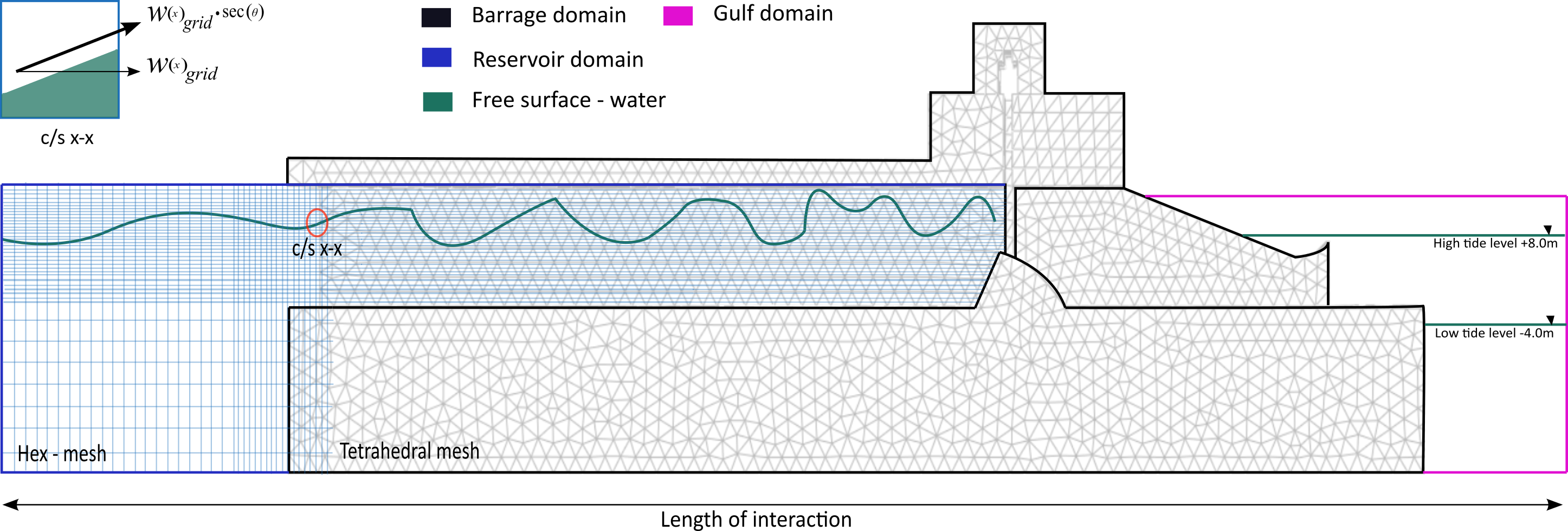
Where, is the horizontal component of the grid velocity inside the reservoir which acts as an Eulerian domain as shown in Fig. 5. A weighted Galerkin approximation is used to modify Eqn. 24 by integrating with a weight function having polynomial to the order of two with respect to the governing fluid property and another weight function with respect to the continuity equation (Kuhl et al., 2003). This reduces the computational errors while solving the ILE equation and can be formulated as-
| (25) |
Where, , , are arbitrary constants and is the shape function of the enclosed water volume inside a computational domain. To compute the solution, we equate as follows-
| (26) |
In coupled Lagrangian-Eulerian technique of solving fluid-structure interaction problems, instead of velocity induced volumetric flow from one computational grid to the other we consider the volumetric water inside a grid to be fixed in temporal space and the grid to be moving from one point to the other within the computational domain (Banks et al., 2016). To address such a technique in the ILE-formulation we need to implement Jacobian interpolation or transformation as shown below-
| (27) |
Where, is the computational grid transformation within a spatial-temporal domain. Eqn. 26 can be re-written in terms of as-
| (28) |
3.2 Lax-Wendroff temporal marching algorithm for ILE computation
Spatial marching is used in this computational scheme to address the effect of velocity-induced grid transformation over a fixed volume of water within the temporal Eulerian domain. A discretization based on the finite element method is implemented to compute the spatial marching using the Lax-Wendroff algorithm as shown below-
| (29) |
The continuity equation is neglected since continuity tends to zero towards the boundary of the Lagrangian-Eulerian interaction domain. Using integration by parts for the time-varying element of the transformed grid and then reversing back to the original grid we get-
| (30) |
Performing time integration from considering the maximum value of as 1.0 and re-writing the term as we get-
| (31) |
Using, spatial finite-element mesh discretization the assembled equation obtained is as follows:
| (32) |
Where, is the mass within the barrage domain, is the mass within the ILE domain, is the finite mass within the sea-water or gulf domain and is the residual matrix within the temporal space calculated at half-step time. Applying the explicit Lax-Wendroff computation scheme, the numerical approximation of Eqn. 32 can be solved using the following relations-
| (33) |
Where, is the Lax-Wendroff flux function and is the computational stability of the temporal domain which can be formulated in terms of the classical Courant-Friedrichs-Lewy parameter () as follows-
| (34) |
where, is the local speed of sound in ideal condition and is the dynamic viscosity of the fluid. The value of is taken as 1500 and the value of is considered as 0.001 (Zeng and Farhat, 2012).
3.3 Critical damping constant computation using Westergaard’s added mass scheme
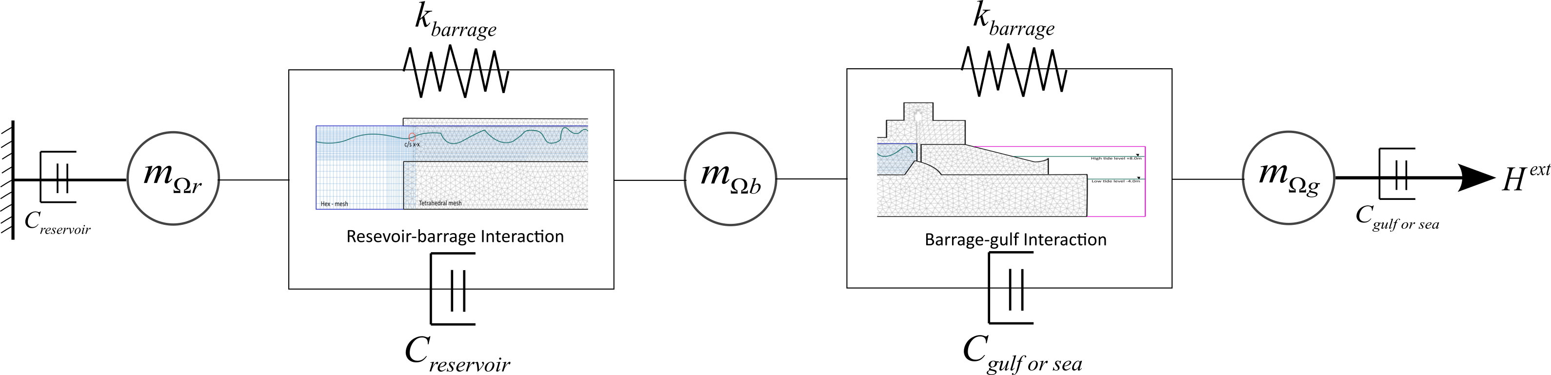
During dynamic excitation from strong ground motion, the barrage-reservoir acts as a critical coupled system. The volumetric mass of the water acts as an added mass damper, damping out the overall motion of the system. The critical damping is computed using Westergaard’s added mass formulation wherein the Rayleigh’s stiffness proportional damping constant is considered. A modified dash-pot system as shown in Fig. 6 is sketched to visualize and compute the required critical damping. The critical damping constant required to compute the Idealized Lagrangian-Eulerian coupling based on Westergaard theory can be formulated from Rayleigh’s damping ratio formula which is valid within the cut-off frequency range or can be computed with respect to the fundamental frequency of vibration as given below-
| (35) |
At, j=1, where the structure undergoes fundamental mode of vibration the minimum value of tends to zero as given (Bea et al., 2009)-
| (36) |
Rearranging the above equation with , and we get-
| (37) |
Where, is Rayleigh’s stiffness proportional damping constant, is the critical damping ratio and is the fundamental frequency of vibration in rads/sec. The idealized pseudo water mass added on the reservoir-barrage interaction side and barrage-gulf interaction side can be computed using-
| (38) |
| (39) |
Where , , is the height of interaction between reservoir and barrage, is the height of interaction between the barrage and gulf, is the maximum reservoir water level and is the water level in the gulf corresponding to low and high tide scenarios.
4 Computation of non-linear dynamic multiphase equation using numerical methods
An improved version of the time-discrete dynamic equilibrium equation for the barrage-reservoir as well as the barrage-gulf interaction can be formulated as follows-
| (40) |
Eqn. 40 can be re-written using matrix expansion as follows-
| (41) |
Where, , and are the near approximated acceleration, velocity and displacement respectively at the node at any time step of . , , are the mass, damping and stiffness matrices of the coupled fluid-structure ILE system respectively.
4.1 Corrected implicit- integration scheme
Using the Newmark difference scheme and can be expanded as following-
| (42) |
| (43) |
{displacement corrector phase for given seismic acceleration}
{velocity corrector phase for given seismic acceleration}
set iterative counter flags for j = 1,2,3….,m to run multiple corrector loop.
If {convergence achieved}
then update and
else return to step-(3) and set counter as and repeat
where, , , are the stability and precision control parameters. To attain unconditional stability and precision up to second order accuracy the value of is taken as -0.166, as 0.339 and as 0.666 using the mathematical relations as follows (Gladwell and Thomas, 1980)-
| (44) |
Rearranging Eqn. 42 and Eqn. 43 the predictor and corrector phases of the non-linear dynamic equation is written as follows (Diethelm et al., 2002)-
| (45) |
| (46) |
| (47) |
| (48) |
Finally, the non linear dynamic equation is computed based on the corrected implicit- integration scheme using a predictor-corrector time marching algorithm presented above as Algorithm 1.
5 Computational validation of EIPDM and CMDFSI numerical schemes
Several significant analyses and research work have been carried out on the Koynanagar dam located in Maharashtra, India. The koynanagar dam is the only largest dam that was exposed to one of the most devastating strong ground shaking dating back to 11th December 1967 with a Richter scale of 6.7-Mw. Extensive cracks were formed on both the downstream and upstream slopes causing critical damage to the structure. A non-linear dynamic fracture simulation was performed on the Koynanagar concrete dam model exposed to the 1967 Koynanagar accelerogram using a coaxial rotational crack model and Lagrangian fluid-structure interaction. The finite element technique was adapted to simulate the two-dimensional model of the Koyna dam. This study proposing an improved version of the damage-plasticity model as the material parameter of concrete and an idealized multiphase Lagrangian-Eulerian fluid-structure interaction model is validated with the benchmark results put forward by Calayir and Karaton (2005). The dam foundation interaction is neglected keeping in mind the foundation behaves like a rigid surface with an approximate elastic modulus of 7.22x10⁴ MPa, thus the seismic acceleration has been applied at the interface of the dam and foundation. An Eulerian-Lagrangian single-phase fluid domain is considered with a mass density of 1000 kg/m3, bulk modulus of 2078 MPa, and rotational constrain of 1.6x10⁵ MPa. The speed of sound over the water surface is considered 1570 m/s. The height of interaction between the water and the dam domain is taken as 90 m and the length of interaction for the reservoir domain is considered 210 m. The base of the reservoir is considered as rigid and nodal displacement is taken as zero for the abridged reservoir boundaries and only the free water surface is allowed to undergo sloshing as a part of the idealized single-phase fluid-structure interaction phenomenon. An enhanced isotropic plasticity damage model with tensile damage subroutine is assigned as material behavior of concrete dam.
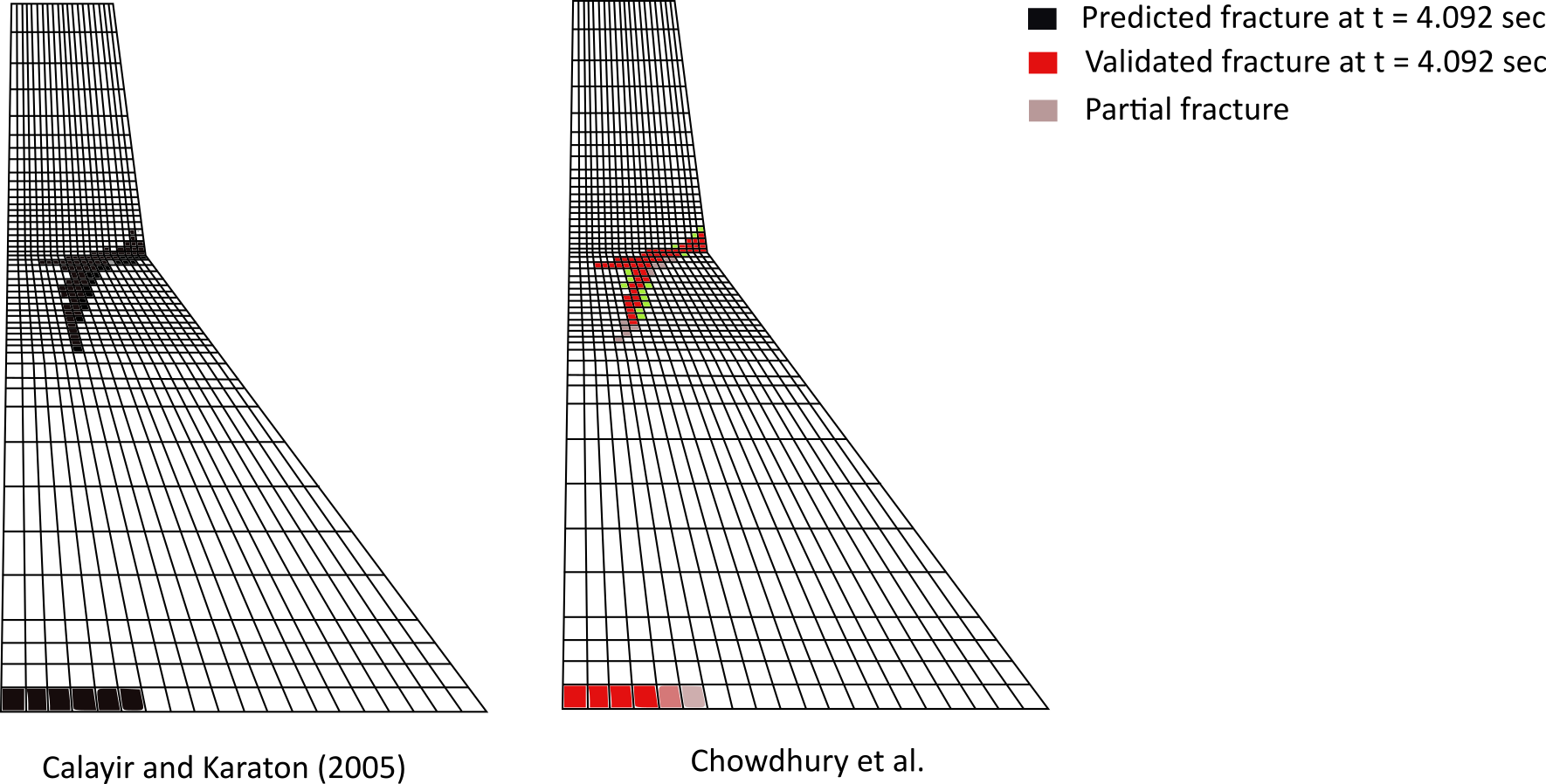
The elastic modulus of the concrete is taken as 27,838 MPa, Poisson ratio as 0.2, mass density as 2670 kg/m3 and yield strength in compression as 31 MPa. Dynamic variation of both elastic moduli of the Eulerian domain as well as the structural domain is ignored in the simulation. Rayleigh’s stiffness proportional damping is considered with critical damping constant of 0.005 and fundamental frequency of vibration as 3.012 cycles/sec. A structured quad-dominated mesh with a 2.5% bias ratio is considered for analysis. Results obtained from finite element simulation using Abaqus is validated against benchmark experimental results obtained by Calayir and Karaton (2005). It is observed that the results obtained in this study are well within the validation domain with 94.12% accuracy. The fracture profile obtained by Calayir et al. spreads over a range of 34 unique nodal points near the upper portion of the downstream monolith whereas the profile obtained by this study spreads over a range of 32 unique nodal points at seismic excitation time of 2.4 seconds. As the simulation proceeds further, fracture starts propagating towards the upstream end, and crack opening in form of integration point deletion takes place. A snapshot of the fracture profile generated on the dam monolith at an excitation time of 4.092 seconds is successfully captured and validated as shown in Fig. 7. Results obtained by Calayir et al. captured 80 unique nodal points undergoing damage whereas computations performed in this study captured 74 unique nodal points undergoing damage near the upper portion of the monolith with an accuracy of 92.6%. The enhanced isotropic plasticity damage mechanical model proposed in this study is able to capture a smooth fracture profile that is computationally stable than those obtained in the benchmark experiment. The Coaxial Rotational Crack model used by Calayir et al. did not consider the losses in fracture energy while interpolating the tension softening behavior of the material and thus could only capture a coarse fracture path. Since fracture energy losses is incorporated with the plasticity damage equation in the present study, even partially fractured element or rather elements that falls under the critical fracture path is smoothly captured and highlighted as shown in Fig. 7. It is observed that material yields at an excitation time, t=2.2 seconds and fracture propagation initiates. The majority of the critical damage due to fracture is achieved within t=4.09 seconds of seismic excitation.
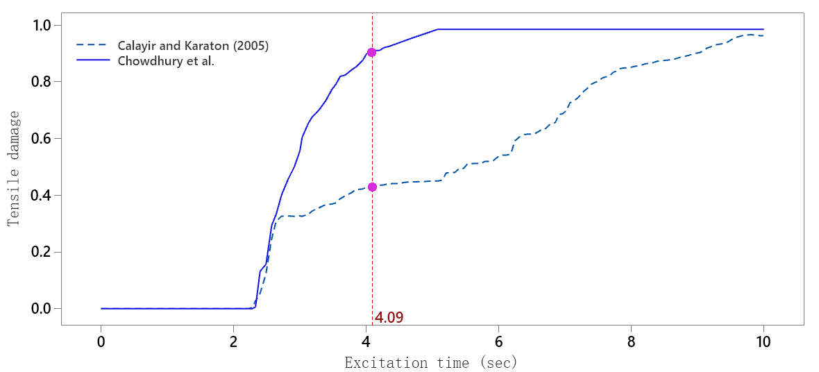
The tensile damage curve obtained from simulations performed by Calayir et al. showed that fracture propagation was quite unstable both before and after critical damage was achieved whereas simulations performed in the present study obtained a much more realistic and stable damage curve which also has a horizontal asymptotic part post time t=5.1 seconds as shown in Fig. 8. The damage parameter in any material should not exceed the ideal value of 1.0 which suggests that once the fracture is achieved and it propagates the damage versus excitation time should saturate at any level below 1.0 or rather behave like an asymptote. Once a material undergoes critical or maximum damage while propagating through the captured path, the damage parameter becomes constant with no further release of fracture energy. This phenomenon is well justified by the simulation results obtained in the present study.
6 Mesh sensitivity analysis and computational stability of EIPDM and CMDFSI
Computational analysis using finite element techniques for materials with assigned plasticity damage mechanical model proposed in this study is critically sensitive to accurate mesh sizes. It is indeed very important to assign a near-perfect grid size to capture realistic profiles of principal stresses and fracture paths from the model. Meshes with both coarse and finesse grid sizes can capture stresses and fracture but the major differences lie in the accuracy of these stresses and fracture paths captured.
Meshes with coarser grid sizes capture discontinuous or rather discrete stress profiles while meshes with finer grid sizes can capture accurate stress profiles having planar continuity. Coarse grid size generates localized regions of stresses that more or less look alike pseudo stress concentrations thus a mesh sensitivity analysis is performed for mesh sizes having a non-dimensional grid to length ratios ranging from 1.0 to 7.0. The computational simulation was performed on both structured CPE4R quad and structured CPE tri meshes.
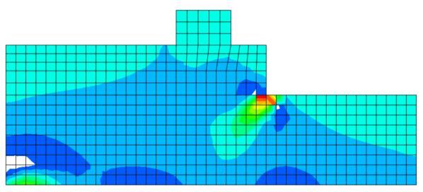
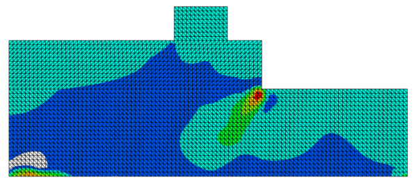
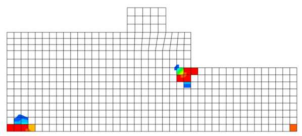
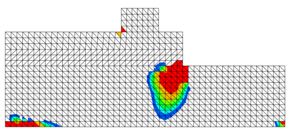
From Fig. 9 it is evident that maximum principal stresses captured by the simulation are distinctive of each other at different levels of mesh finesse and for different types of meshes. For quad dominated CPE4R mesh having a grid to length ratio of 4.2, the critical maximum principle stress spreads discretely through two unique integration points whereas, for a CPE4R quad mesh with a grid length ratio of 2.1, critical maximum principle stress spreads over a continuum region of 7 to 8 unique integration points. For CPE elemental meshes having tri dominated mesh type, the stress profile captured becomes like a stretched ellipse with continuous contour but is more prominent at a higher grid to length ratio. Stretched elliptical profile of stress contour highlights realistic stress flows through the material due to seismic excitation and multiphase fluid-structure interaction. Stress concentration occurs at the location of fracture initiation during computation using only the enhanced version of the plasticity damage mechanical model. When multiphase dynamic fluid-structure interaction is included in the computation along with the enhanced plasticity damage model, the concentrated stresses near the crack opening or fracture initiation region spreads to the adjoining integration points or computational grid, this creates the realistic stretched elliptical stress flow profile as shown in 10b. Finite element computation using structured cosserat point element with three noded triangles gave precise fracture path or rather plane strain yield surface when compared to mesh having four noded quad element. From 9a and 9b it is observed that discrete fracture paths were obtained for quad meshing with a grid to length ratio of 4.2 whereas, the fracture surface obtained for tri meshing with the same grid to length ratio was having a near elliptical and continuous profile towards the top. Each and every type of mesh behaves differently with a varying grid to length ratios thus it is very difficult to arrive at a suitable or rather optimized grid to length ratio for obtaining accurate computational results. Based on observations from contours shown in Fig. 9 and Fig. 10, three noded CPE type element is adopted for computational stability analysis. Instability in computation arises when the grids inside a mesh are either two closely spaced forming regions of overlap or are too widely stretched. Widely stretched grids inside any mesh domain result in isoparametric distortion which further delays the convergence of equilibrium iterations (Lee and Bathe, 1993).
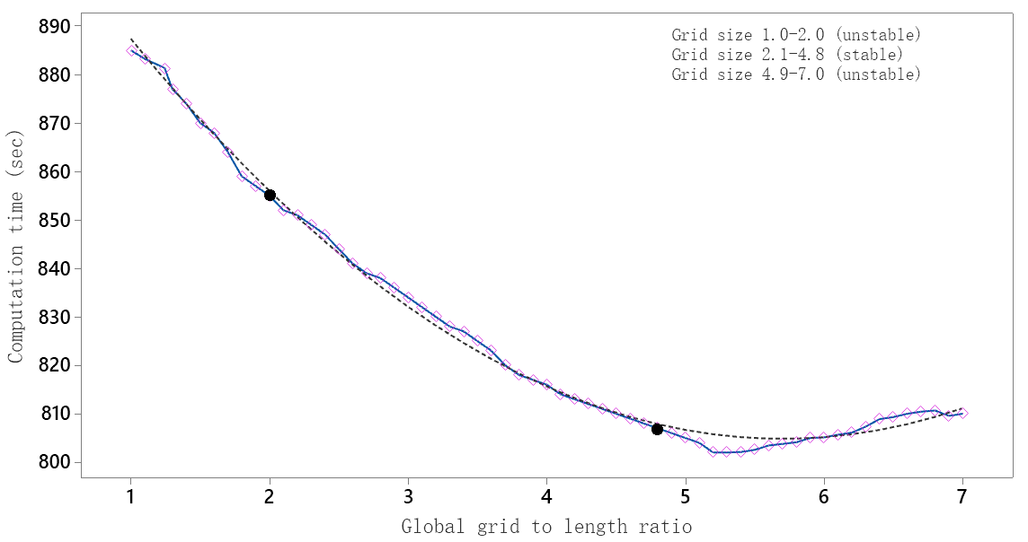
From Fig. 11 it is observed that with an increase in the global grid to length ratio from 1.0 to 5.0, the time required for computational convergence decreases, and post 5.0 the computation time increases. A cubic interpolation curve is fitted to study the stability parameter and it is observed that due to excessive grid overlapping, the computation curve is unstable for a grid to length ratio ranging from 1.0 to 2.0. Post 4.9, the curve becomes unstable yet again due to excessive stretching of the grids inside the mesh. Optimum computational stability is achieved only when the ratio was set between a range of 3.6 to 4.8.
7 Response of tidal barrage to seismic excitation using EIPDM and CMDFSI
A three-dimensional model of the tidal barrage present within the enclosure of the Kalpasar dam is simulated using finite element computation in Abaqus to study the fracture propagation due to seismic excitation. The improved damage plasticity mechanical model and idealized Lagrangian-Eulerian multiphase fluid-structure interaction model are adopted for computational simulation. The width and height of the barrage is taken as 205 m and 52 m respectively. The width and height of the discharge channel are taken as 92 m and 14 m respectively. A crested ogee is modeled at the discharge end having a curvature profile of towards the downstream monolith and a 1:1 linear slope towards the upstream monolith. The overall length of the barrage is around 1200 m to 1300 m which is beyond the computational scope of this study thus an effective length between two construction joints from the barrage is considered for analysis and the value is taken as 182 m approximately.
|
|
|
|
|
||||||||||
|---|---|---|---|---|---|---|---|---|---|---|---|---|---|---|
| 0.7* | 3834057.903 | 0 | 0 | 0 | ||||||||||
| 0.467* | 2553482.563 | 2.00E-05 | 0.334 | 0.313 | ||||||||||
| 0.263* | 1437771.713 | 0.00011 | 0.625 | 0.611 | ||||||||||
| 0.117* | 638754.0466 | 0.00021 | 0.8334 | 0.812 | ||||||||||
| 0.0086* | 47144.9958 | 0.0005 | 0.98770363 | 0.9788 | ||||||||||
| 0 | 0 | 0.00056 | 1 | 1 |
The width of the Eulerian domain is taken as 50 m without any interaction and an additional 95 m with interaction. The maximum water level reached at the reservoir end within a complete tidal cycle is considered to be the equivalent height of interaction for the Eulerian domain and the value is adopted as 6.99 m. An undeformable rigid plate is assigned to the bottom boundary of the Eulerian domain and the remaining truncated boundaries are assigned with zero degrees of freedom. Only the top surface of the Eulerian domain is allowed to undergo deformation analogous to a free water surface under seismic excitation. The interaction of barrage bottom with it’s foundation having rocks and granites with an approximate elastic modulus of 7.17x10⁴ MPa behaves quite rigidly thus neglected in the simulation.
A pseudo volumetric water mass is assigned to the Eulerian domain having a mass density of 1000 kg/m3, bulk modulus of 2060 MPa, and rotational constrain of 1.54x10⁵ MPa. The speed of sound over the free water surface is assigned as 1500 m/s. The enhanched version of the plasticity damage mechanical model proposed in this study with values as given in Table 1 is adopted. The elastic modulus of M-30 Indian standard mix concrete is considered as 27.386 MPa, Poisson ratio as 0.28, mass density as 2670 kg/m3 and yield strength in compression as 30 MPa. The dynamic variation of elastic modulus with time during seismic excitation is neglected. A linear perturbation analysis is performed to extract the modal frequencies of the barrage under seismic excitation. Solving Eqn. 36 with fundamental frequency as 2.805 and critical damping as 0.003, Rayleigh’s stiffness proportional damping constant is obtained with a value of 0.003404. The transverse and vertical seismic loads assigned are extracted from
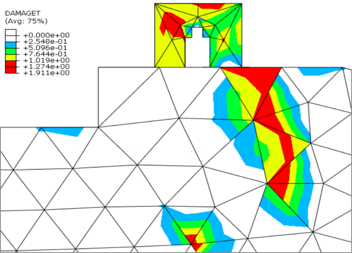
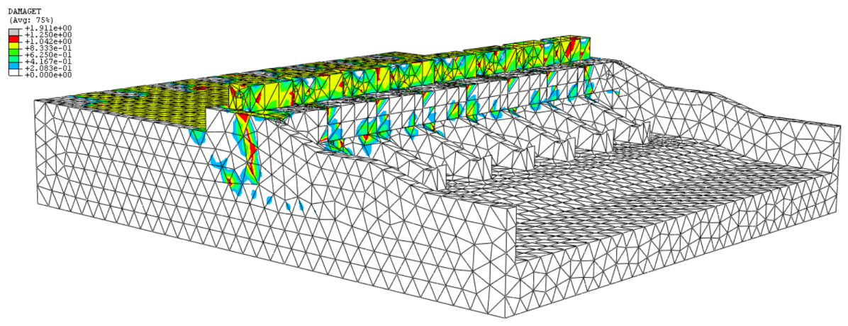
the strong ground motion data recorded for a historic love wave propagating from station ALIR to station GIRNAR directly passing below the Kalpasar dam through the Cambay rift as shown in Fig. 1 having a magnitude of Mw-6.7 as per Richter scale. The strong ground data is extracted from historic love wave propagating from station ALIR to station GIRNAR then filtered and plotted against an excitation time of 10 seconds. Based on mesh sensitivity and stability computation as shown in Fig. 11, a C3D4H type tetrahedral which is a three-dimensional hybrid form of hex mesh with a global grid to length ratio of 4.2 is adopted for analysis. From Fig. 12 it is observed that the damage is mostly localized in the upper region of the barrage with cracks initiating from the gate housing and propagating through the retaining wall up to a height of 15 meters from the top elevation. The majority of the damage occurred at the reservoir end and on the surfaces of both the retaining walls. The fracture profile on the left retaining wall with a stretched elliptical yield surface propagated at an angle of 22.5°from the vertical while that on the right retaining wall propagated at an angle of 75°from the vertical. From Fig. 12, it is also observed that the inner surface of the left retaining wall has patches of tensile damage near the bottom lining of the barrage. It is also observed that damage propagates at the intersection of gate housing and training piers.
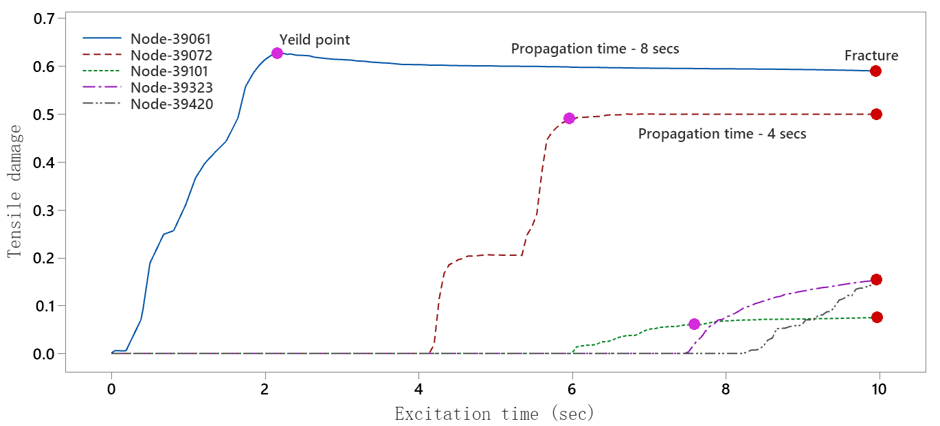
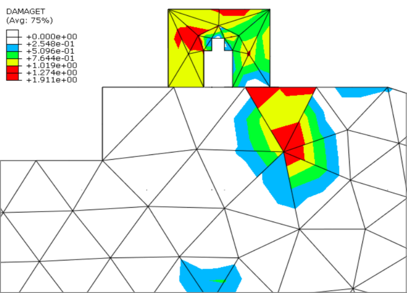
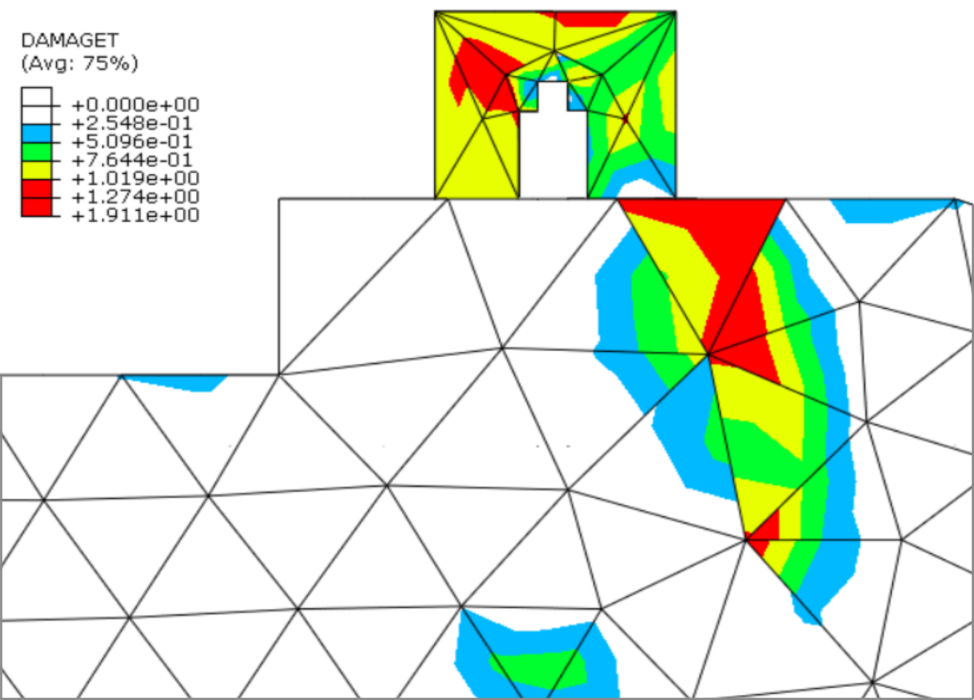
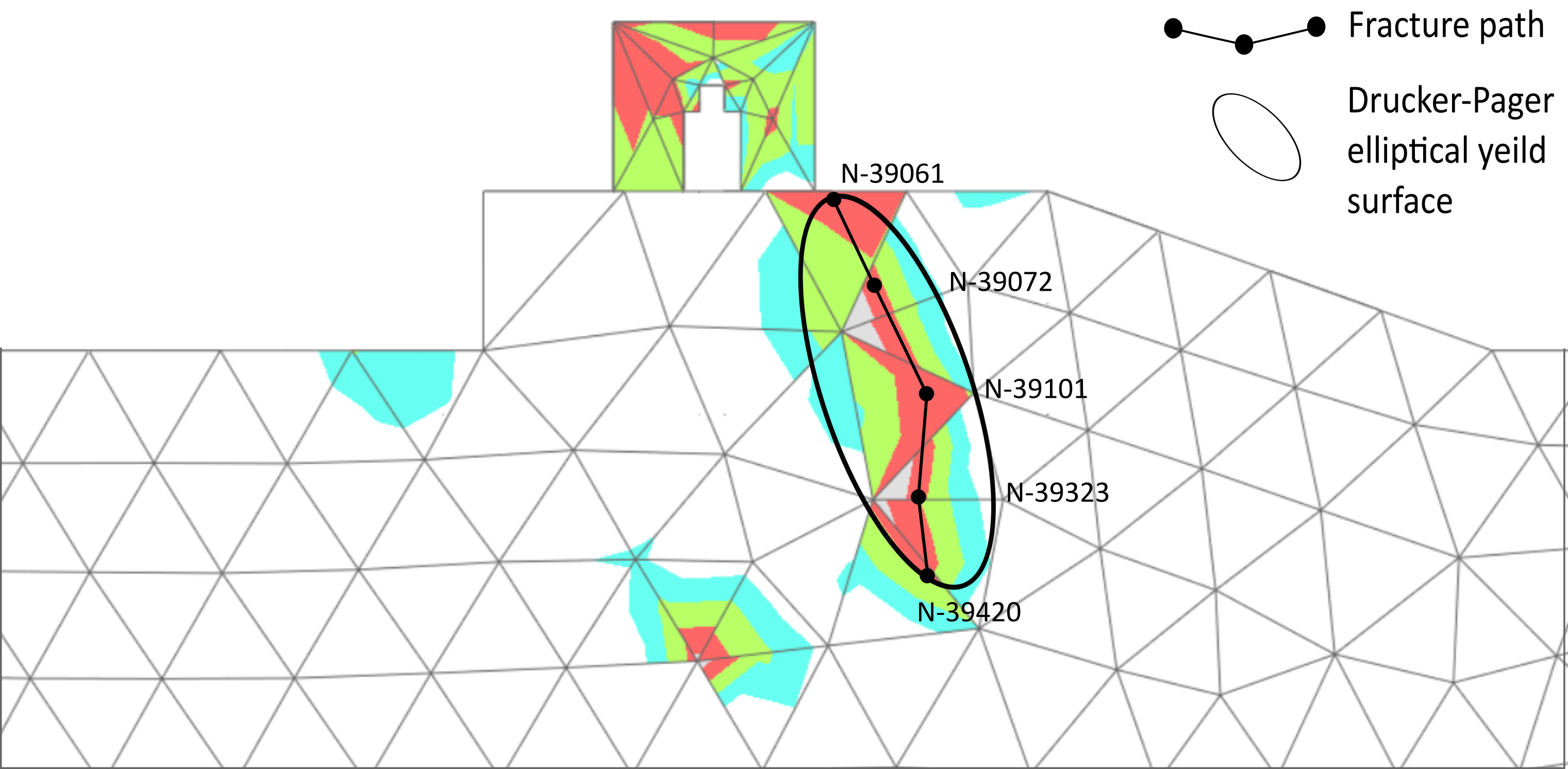
The fracture propagation on the outer surface of the left retaining wall at different excitation times is shown in Fig. 13 and it is observed that fracture at any tetrahedral element initiates at the integration point present at one of the apex and propagates towards another apex through triangular planes and is divergent in nature. As the excitation time approaches 10 seconds, the fracture propagation patterns slowly become convergent in nature and stretch out on the yield surface giving a much more realistic profile. The divergent spreading is captured in 13a whereas the convergent spreading is evident from 13c. While formulating the enhanced version of the plasticity damage mechanical model, an elliptical Drucker-Pager yield surface defined by a hyperbolic yield function was proposed shown in Fig. 3 and formulated as Eqn. 12. The formulation stands valid as the yield surface captured in the simulation comes out to be a stretched elliptical one with cracks propagating from one end of the major axis towards the other.Fig. 14 highlights the elliptical profile captured with crack initiating from node 39061 located at the elevation of +12.20 m from mean sea level and ending at node 39420 located at -3.80 m from the mean sea level. In the initial stage of seismic excitation, it is observed that fracture initiated at node 39061, yields corresponding to a damage value of 0.63, and fracture propagates slowly and steadily for an average time period of 8 seconds. As the excitation time increases, nodes start yielding at damage values lower than 0.63 and the propagation time also decreases from 8 to 4 seconds. At the final phase of the excitation material yields corresponding to damage value as low as 0.1 and failure occurs without any significant fracture propagation as shown in Fig. 15.
8 Conclusions
In this study, the fracture and damage response of a concrete tidal barrage due to seismic excitation is investigated based on a coupled multiphase fluid-structure interaction between the barrage, reservoir and the gulf. An improved numerical version of the existing plasticity damage mechanical model is formulated by restoring the additional fracture energy losses. The enhanced isotropic plasticity damage mechanical model is also validated against results obtained from benchmark experiments performed by several researchers on the Koyna Dam. Validation showcased 92% to 95% accuracy with realistic fracture growth profiles. Finite element meshing is performed with C3D4H-tetrahedral elements having a global grid to length ratio of 4.2 adopted based on mesh sensitivity and computational stability analysis. Element nodal matrices obtained from the coupled multiphase fluid-structure interaction model are assembled numerically using the Lax-Wendroff temporal marching scheme. The non-linear coupled multiphase dynamic equation is solved using a corrected implicit- integration scheme and predictor-corrector time marching algorithm based on the fracture mechanics principle. Computation using an uncoupled Lagrangian model captured localized stress and pressure concentration near the fracture path within the yield surface, this additional concentration accelerated the crack growth and the fracture profile obtained was wider and coarse. The idealized multiphase fluid-structure interaction formulated using coupled Lagrangian-Eulerian model is able to distribute or rather eradicate the concentrated pressure and stresses near the crack tip which resulted in the formation of a realistic and stretched fracture path with moderate to fine crack width. Fracture initiates at the bottom of the gate housing and propagates through an elliptical Drucker-Pager yield surface till the mid-region of the retaining wall. The majority of the damage occurs at the outer and inner surface of the retaining wall and also at monoliths connecting piers with gate housing. After material yields, fracture propagates rather slowly during the initiation phase whereas, towards the end of seismic excitation failure and fracture occur simultaneously without sufficient warnings.
References
- Banks et al. (2016) Banks, J.W., Henshaw, W.D., Kapila, A.K., Schwendeman, D.W., 2016. An added-mass partition algorithm for fluid–structure interactions of compressible fluids and nonlinear solids. Journal of Computational Physics 305, 1037–1064. doi:10.1016/J.JCP.2015.10.043.
- Bazant (1985) Bazant, Z.P., 1985. MECHANICS OF FRACTURE AND PROGRESSIVE CRACKING IN CONCRETE STRUCTURES. Fract Mech of Concr, Struct Appl and Numer Calc , 1–94URL: https://link.springer.com/chapter/10.1007/978-94-009-6152-4{_}1, doi:10.1007/978-94-009-6152-4_1/COVER.
- Bea et al. (2009) Bea, J.J., Kim, H.S., Kim, Y.G., Lee, J.H., 2009. Earthquake Analysis of Dam Floodgate Using Calibrated Added Mass. Journal of the Earthquake Engineering Society of Korea 13, 31–40. doi:10.5000/EESK.2009.13.5.031.
- Brühwiler and Wittmann (1990) Brühwiler, E., Wittmann, F.H., 1990. The wedge splitting test, a new method of performing stable fracture mechanics tests. Engineering Fracture Mechanics 35, 117–125. doi:10.1016/0013-7944(90)90189-N.
- Calayir and Karaton (2005) Calayir, Y., Karaton, M., 2005. Seismic fracture analysis of concrete gravity dams including dam–reservoir interaction. Computers & Structures 83, 1595–1606. doi:10.1016/J.COMPSTRUC.2005.02.003.
- Cervera and Chiumenti (2006) Cervera, M., Chiumenti, M., 2006. Smeared crack approach: back to the original track. International Journal for Numerical and Analytical Methods in Geomechanics 30, 1173–1199. doi:10.1002/NAG.518.
- Chang and Pan (1997) Chang, W.J., Pan, J., 1997. Effects of yield surface shape and round-off vertex on crack-tip fields for pressure-sensitive materials. International Journal of Solids and Structures 34, 3291–3320. doi:10.1016/S0020-7683(96)00191-6.
- Chopra and Chakrabarti (1973) Chopra, A.K., Chakrabarti, P., 1973. The Koyna earthquake and the damage to Koyna Dam. Bulletin of the Seismological Society of America 63, 381–397. doi:10.1785/BSSA0630020381.
- Chopra et al. (2008) Chopra, S., Yadav, R.B., Patel, H., Kumar, S., Rao, K.M., Rastogi, B.K., Hameed, A., Srivastava, S., 2008. The Gujarat (India) Seismic Network. Seismological Research Letters 79, 806–815. doi:10.1785/GSSRL.79.6.806.
- Chorin (1968) Chorin, A.J., 1968. Numerical solution of the Navier-Stokes equations. Mathematics of Computation 22, 745–762. doi:10.1090/S0025-5718-1968-0242392-2.
- Choudhury et al. (2018) Choudhury, P., Chopra, S., Kumar, M.R., 2018. A review of seismic hazard assessment of Gujarat: A highly active intra-plate region. Earth-Science Reviews 187, 205–218. doi:10.1016/J.EARSCIREV.2018.09.014.
- Diethelm et al. (2002) Diethelm, K., Ford, N.J., Freed, A.D., 2002. A Predictor-Corrector Approach for the Numerical Solution of Fractional Differential Equations. Nonlinear Dynamics 2002 29:1 29, 3–22. doi:10.1023/A:1016592219341.
- Gladwell and Thomas (1980) Gladwell, I., Thomas, R., 1980. Stability properties of the Newmark, Houbolt and Wilson methods. International Journal for Numerical and Analytical Methods in Geomechanics 4, 143–158. doi:10.1002/NAG.1610040205.
- Grassl et al. (2013) Grassl, P., Xenos, D., Nyström, U., Rempling, R., Gylltoft, K., 2013. CDPM2: A damage-plasticity approach to modelling the failure of concrete. International Journal of Solids and Structures 50, 3805–3816. doi:10.1016/J.IJSOLSTR.2013.07.008, arXiv:1307.6998.
- Hafezolghorani et al. (2018) Hafezolghorani, M., Hejazi, F., Vaghei, R., Jaafar, M.S.B., Karimzade, K., 2018. Simplified Damage Plasticity Model for Concrete. https://doi.org/10.2749/101686616X1081 27, 68–78. doi:10.2749/101686616X1081.
- Hall (1988) Hall, J.F., 1988. The dynamic and earthquake behaviour of concrete dams: review of experimental behaviour and observational evidence. Soil Dynamics and Earthquake Engineering 7, 58–121. doi:10.1016/S0267-7261(88)80001-0.
- Hanks and McGuire (1981) Hanks, T.C., McGuire, R.K., 1981. The character of high-frequency strong ground motion. Bulletin of the Seismological Society of America 71, 2071–2095. doi:10.1785/BSSA0710062071.
- Hillerborg (1985) Hillerborg, A., 1985. The theoretical basis of a method to determine the fracture energyG F of concrete. Materials and Structures 1985 18:4 18, 291–296. doi:10.1007/BF02472919.
- Hirt et al. (1970) Hirt, C.W., Cook, J.L., Butler, T.D., 1970. A lagrangian method for calculating the dynamics of an incompressible fluid with free surface. Journal of Computational Physics 5, 103–124. doi:10.1016/0021-9991(70)90055-0.
- Kolathayar et al. (2019) Kolathayar, S., Sitharam, T.G., Yang, S., 2019. Coastal reservoir strategy to enhance India’s freshwater storage by impounding river flood waters: a detailed overview. Water Supply 19, 703–717. doi:10.2166/WS.2018.140.
- Kuhl et al. (2003) Kuhl, E., Hulshoff, S., de Borst, R., 2003. An arbitrary Lagrangian Eulerian finite-element approach for fluid–structure interaction phenomena. International Journal for Numerical Methods in Engineering 57, 117–142. doi:10.1002/NME.749.
- Lee and Bathe (1993) Lee, N.S., Bathe, K.J., 1993. Effects of element distortions on the performance of isoparametric elements. International Journal for Numerical Methods in Engineering 36, 3553–3576. doi:10.1002/NME.1620362009.
- Mridha and Maity (2014) Mridha, S., Maity, D., 2014. Experimental investigation on nonlinear dynamic response of concrete gravity dam-reservoir system. Engineering Structures 80, 289–297. doi:10.1016/J.ENGSTRUCT.2014.09.017.
- Murali and Sundar (2017) Murali, K., Sundar, V., 2017. Reassessment of tidal energy potential in India and a decision-making tool for tidal energy technology selection:. http://dx.doi.org/10.1177/1759313117694629 8, 85–97. doi:10.1177/1759313117694629.
- Ni and Barazangi (1984) Ni, J., Barazangi, M., 1984. Seismotectonics of the Himalayan Collision Zone: Geometry of the underthrusting Indian Plate beneath the Himalaya. Journal of Geophysical Research: Solid Earth 89, 1147–1163. doi:10.1029/JB089IB02P01147.
- Pal (1976) Pal, N., 1976. Seismic Cracking of Concrete Gravity Dams. Journal of the Structural Division 102, 1827–1844. doi:10.1061/JSDEAG.0004432.
- Petrov et al. (2012) Petrov, Y.V., Karihaloo, B.L., Bratov, V.V., Bragov, A.M., 2012. Multi-scale dynamic fracture model for quasi-brittle materials. International Journal of Engineering Science 61, 3–9. doi:10.1016/J.IJENGSCI.2012.06.004.
- Reinhardt et al. (1986) Reinhardt, H.W., Cornelissen, H.A.W., Hordijk, D.A., 1986. Tensile Tests and Failure Analysis of Concrete. Journal of Structural Engineering 112, 2462–2477. doi:10.1061/(ASCE)0733-9445(1986)112:11(2462).
- Sitharam (2017) Sitharam, T., 2017. Efficacy of coastal reservoirs to address India’s water shortage by impounding excess river flood waters near the coast. Journal of Sustainable Urbanization, Planning and Progress 2, 49–54. doi:10.26789/JSUPP.2017.02.008.
- Subba Rao (2011) Subba Rao, D.V., 2011. Kalpasar: Potential Coastal Impacts for India of a Mega-Engineering Project “Fulfilling All Wishes”. Environmental Science and Engineering , 717–740doi:10.1007/978-3-642-14779-1_32/COVER.
- Tekie and Ellingwood (2003) Tekie, P.B., Ellingwood, B.R., 2003. Seismic fragility assessment of concrete gravity dams. Earthquake Engineering & Structural Dynamics 32, 2221–2240. doi:10.1002/EQE.325.
- Voyiadjis et al. (2008) Voyiadjis, G.Z., Taqieddin, Z.N., Kattan, P.I., 2008. Anisotropic damage–plasticity model for concrete. International Journal of Plasticity 24, 1946–1965. doi:10.1016/J.IJPLAS.2008.04.002.
- Yazdani and Schreyer (1990) Yazdani, S., Schreyer, H.L., 1990. Combined Plasticity and Damage Mechanics Model for Plain Concrete. Journal of Engineering Mechanics 116, 1435–1450. doi:10.1061/(ASCE)0733-9399(1990)116:7(1435).
- Zeng and Farhat (2012) Zeng, X., Farhat, C., 2012. A systematic approach for constructing higher-order immersed boundary and ghost fluid methods for fluid–structure interaction problems. Journal of Computational Physics 231, 2892–2923. doi:10.1016/J.JCP.2011.12.027.