Stable high-transformer ratio beam-wakefield acceleration in cusp plasma channels
Abstract
Wakefield excitation by structured electron bunches in hollow gaps between plasma wedges is studied using three-dimensional particle-in-cell simulations. The main part of the electron bunch has a triangular current distribution in the longitudinal direction with a smooth head and short tail. These bunches propagate stably in the hollow gap while being attached to cusps of the plasma wedges. The excited wakefield profile may have a very high transformer ratio and allows to accelerate witness bunches to energies much higher than that of the driver bunch. Unlike round hollow channels, where asymmetric wakefields are difficult to avoid, no deleterious transverse beam break-up (BBU) is observed in the gap between cusp-shaped plasma layers.
Plasma-based particle acceleration is able to provide huge accelerating fields on the order of or potentially even TV/m [1, 2, 3, 4, 5, 6]. The wakefields are generated either by intense laser pulses [1, 7], or by bunches of charged particles [5, 6]. Although the laser technology is developing very fast, the currently available particle beam drivers can provide much higher average powers. The major problem with the beam-driven plasma wakefields is the low transformer ratio , where is the accelerating field acting on the witness and is the drag field that is stopping the driver. One can easily show that for a symmetric driver, [8]. A beam loading of the wake by the witness will further decrease this ratio. Thus, many stages are required to accelerate the witness to energies much higher than that of the driver [9]. An efficient coupling between multiple plasma acceleration sections is still an unresolved problem. Thus, it important to reduce the number of stages in a plasma-based accelerator. In an optimal case, the whole acceleration process must be accomplished within one single plasma stage. For the beam-driven acceleration this requires , unless the driver has already a very high energy [10].
It is well known that structured bunches can generate wakefields with high transformer ratios. This can be continuous bunches with triangular current profiles [11] or tailored sequences of square bunches [12, 13]. Long drivers cannot be used in uniform plasmas as they are subject to the self-modulation instability [14]. At the same time, generation of skewed wakefields and the resulting beam break-up (BBU) [15] limits acceleration gradients in hollow channels [16]. The stable acceleration is then defined by focusing strength of available quadrupole magnets.
Another significant challenge is the efficient plasma-based acceleration of positrons. While plasma allows for highly energy efficient acceleration of electron bunches in the bubble regime [17, 18], positrons can be accelerated in the quasi-linear regime [3]. The latter is rather inefficient energetically and it is difficult to conserve emittance of positively charged witness bunches. A few exotic schemes for positron acceleration have been proposed recently [19, 20, 21, 22, 23]. These still have to be verified experimentally.
In this work, we propose a new plasma structure that naturally allows for stable propagation of very long driver bunches and generaton of wakefields with high transformer ratios. The plasma structure consists of two plasma wedges with a hollow gap between the cusps as shown in Fig.1. The gap width is large in comparison with the plasma skin length, , where , and is the plasma electron density, is the elementary charge, is the electron density. The driver propagating inside the hollow gap has two stable positions at the cusps of the both plasma layers. A negatively charged driver expels plasma electrons and leaves naked ions at the edges of the plasma layers. These ions are heavy, move rather slowly and their focusing field attracts the driver bunch to the inner edges of the plasma layers.
Analytical theory of wakefields fields inside the hollow gap of such shape is a complicated task and will be done in a separate publication. Here, we present simulation results using the fully electromagnetic three-dimensional (3D) particle-in-cell (PIC) code VLPL [24, 25, 26].
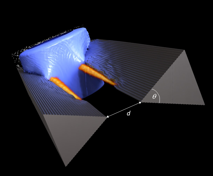
The simulated configuration has the following parameters. Electron density in the plasma is . This corresponds to the plasma skin length . The opening angle of the plasma wedges is . The gap width
The simulation box size is with grid cells . The simulated propagation distance was
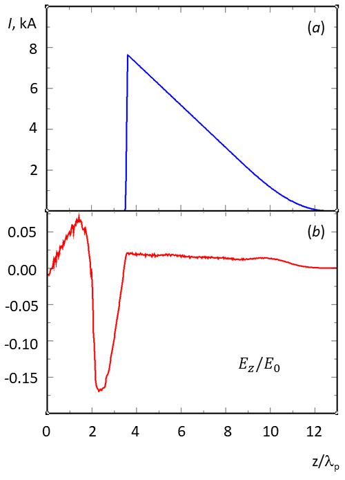
We use two driver electron bunches with population of each, initial energy of and transverse emittance The driver longitudinal current profile is triangular with a smooth leading head as shown in Fig.2a. The driver bunches propagate along the plasma wedge cusps. The generated longitudinal wakefield in the center of the gap is shown in Fig.2b. The theoretical transformer ratio here is , where is the maximum accelerating field of the wake and is the maximum decelerating field acting on the driver.
To prove the acceleration, we inject a witness bunch of test electrons with initial energy of into the negative wakefield bucket just behind the driver. The witness electron bunch has a Gaussian density shape with and .
In addition, we inject a witness bunch of test positrons with the same initial energy and density profile into the positive wakefield bucket.
Two-dimensional cuts of the driver bunch density plasma electron density , component of the radial force acting on positively charged relativistic particles running in direction, wakefield , witness electron bunch, and witness positron bunch are shown in Fig.3 after propagation distance of All the forces are normalized to the limiting “wavebreaking force” .
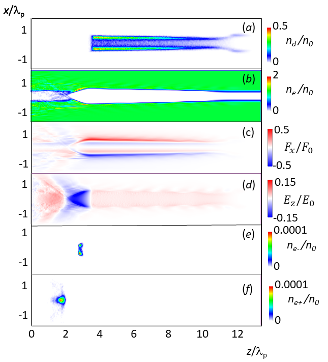
The driver bunch takes on a typical “claw”-like shape. The low density head of the bunch propagates inside the plasma wedge. However, as the driver density rises, its transverse electric field becomes strong enough to expel all electrons from the plasma cusp. As a result, the main body of the driver is attached to the cusp and remains stable over the whole acceleration distance.
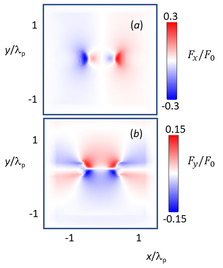
The force focuses driver electrons to the cusps. Its components and in the transverse plane are shown in Fig.4. The -component focuses the driver everywhere in the gap towards the plane. The -component defocuses the electrons from the axis and attracts it to the cusps positions. Inside plasma wedges, the focusing is decaying withing the plasma skin depth. The focusing to the cusps remains in the first negative bucket behind the driver. Here we inject the electron witness bunch. This bunch splits into two bunches, each being attracted to the plasma cusps. Just behind the first negative wakefield bucket, a flash of plasma electrons is ejected from the plasma wedge into the gap. As these electrons reach the axis, they focus the witness positron bunch to the axis within the positive wakefield bucket.
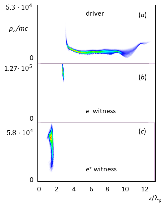
Longitudinal phase spaces of the bunches after are shown in Fig.6. In the driver bunch, Fig.6a, electrons close to the bunch head have lost up to energy, while the central bulk of the driver has lost about energy. This means, the shape of the driver does not perfectly fit as it excites a nonlinear wake. Apparently, the transition region between the low density “claws” at the head of the driver and its bulk body excites a wakefield. Thus, the driver shape requires further optimization. However, optimization is not a goal of the present work and will be done elsewhere.

Electrons in the witness bunch, Fig.6b, have been accelerated up to . This gain of corresponds to a transformer ratio for the electron acceleration is . It remained stable over the full acceleration distance.
The positron witness bunch, Fig.6c, also remained stable and was accelerated up to The energy gain of gives the transformer ratio for the positron acceleration about . It is smaller than for the electrons, because a significant part of the wakefield energy has been lost in the transverse wavebreaking process as the plasma electrons were sucked into the gap.
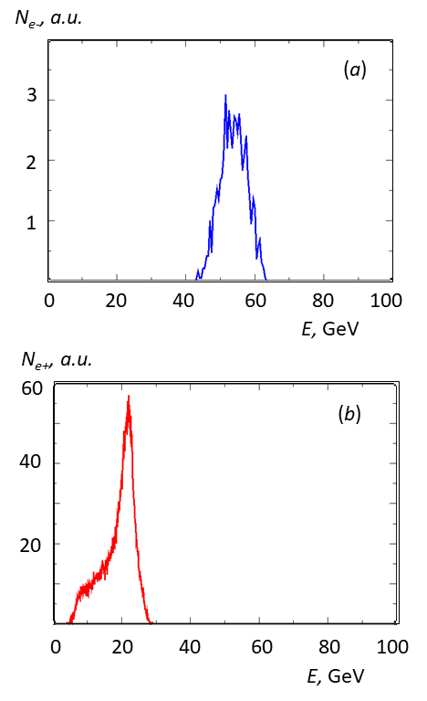
The final energy spectrum of the driver is given in Fig.7. The main body of the driver lost energy down to while a few electrons in the very tail we accelerated. Spectra of witness bunches are shown in Fig.8a,b. These are not monoenergetic, because we used test particles to prove the stability of acceleration. A proper beam-loading using bunches with matched profiles should lead to monoenergetic spectra. This optimization work, however, is again outside of the scope of the present work and will be done elsewhere.

Concerning the final emittance of the witness bunches, we do not provide any numbers here as they are unreliable due to the limited numerical resolution. We do observe a significant transverse heating of the driver and the witnesses. However, this heating is numerical and is reduced when we increase numerical resolution. Unfortunately, doubling the resolution in all dimensions increases simulation time by factor , when the fully electromagnetic 3D PIC code is used. More efficient numerical tools for simulation of this configuration have to be developed.
In conclusion, we have shown that structures consisting of plasma wedges with a vacuum gap in between allow for stable propagation of long electron driver bunches. Properly shaped driver excite wakefields with high transformer ratios and can accelrate both electrons to energies higher than that of the driver. Also positrons can be accelerated in these structures. This may help to reduce or even avoid staging in plasma-based acceleration and open paths towards single-stage high energy accelerators.
This work has been supported by the Deutsche Forschungsgemeinschaft. The authors gratefully acknowledge the Gauss Centre for Supercomputing e.V. (www.gauss-centre.eu) for funding this project by providing computing time through the John von Neumann Institute for Computing (NIC) on the GCS Supercomputer JUWELS at Jülich Supercomputing Centre (JSC).
References
- [1] W.P. Leemans and E. Esarey, Laser-driven plasma-wave electron accelerators Physics Today 62, 44 (2009)
- [2] E. Adli, J.-P. Delahaye, S. J. Gessner, M. J. Hogan, T. Raubenheimer, W. An, Ch. Joshi, W. Mori, A Beam Driven Plasma-Wakefield Linear Collider: From Higgs Factory to Multi-TeV, Proceedings of the 2021 US Community Study on the Future of Particle Physics
- [3] S. Corde et al., Multi-gigaelectronvolt acceleration of positrons in a self-loaded plasma wakefield, Nature (London) 524, 442 (2015)
- [4] S. Gessner et al., Demonstration of a positron beam- driven hollow channel plasma wakefield accelerator, Nat. Commun. 7, 11785 (2016)
- [5] V. Yakimenko et al., FACET-II facility for advanced ac- celerator experimental tests, Phys. Rev. Accel. Beams 22, 101301 (2019)
- [6] R. D’Arcy et al., FLASHForward: plasma wakefield accelerator science for high-average-power applications, Phil. Trans. Roy. Soc. A 377, 20180392 (2019).
- [7] C. Aniculaesei et al. The acceleration of a high-charge electron bunch to 10 GeV in a 10-cm nanoparticle-assisted wakefield accelerator Matter Radiat. Extremes 9, 014001 (2024) https://doi.org/10.1063/5.0161687R. D. Ruth, A. W. Chao, P. L. Morton, and P. B. Wilson, A plasma wake field accelerator Part. Accel. 17, 171 (1985)
- [8] R. D. Ruth, A. W. Chao, P. L. Morton, and P. B. Wilson, A plasma wake field accelerator Part. Accel. 17, 171 (1985)
- [9] B. Foster, R. D’Arcy, and C. A. Lindstrøm A hybrid, asymmetric, linear Higgs factory based on plasma-wakefield and radio-frequency acceleration arXiv:2303.10150v3 (2024)
- [10] A Caldwell, K Lotov, A Pukhov, F Simon Proton-driven plasma-wakefield acceleration Nature Physics 5 (5), 363-367 (2009)
- [11] K.L. Bane, P. Chen, P.B. Wilson, On collinear wake field acceleration IEEE Trans. Nucl. Sci. 32 3524 (1985)
- [12] J. Power, W. Gai, and A. Kanareykin, Transformer ratio enhancement using a ramped bunch train in a collinear wakefield accelerator in Proceedings of the 9th Advanced Accelerator Concepts Workshop (2000).
- [13] J. P. Farmer, R. Martorelli, and A. Pukhov Transformer ratio saturation in a beam-driven wakefield accelerator Physics of Plasmas 22, 123113 (2015) https://doi.org/10.1063/1.4938038
- [14] A Pukhov, N Kumar, T Tückmantel, A Upadhyay, K Lotov, P Muggli, Phase velocity and particle injection in a self-modulated proton-driven plasma wakefield accelerator Physical review letters 107, 145003 (2011)
- [15] VV. Balakin, S. Novokhatsky, V. Smirnov, Transverse Beam Dynamics, Proc. 12th Int. Conf. on High Energy Acc., Batavia, Illinois, (1983) p.119- 120,
- [16] S.S.Baturin, A. Zholents, Stability condition for the drive bunch in a collinear wakefield accelerator, Phys. Rev. AB 21, 031301 (2018)
- [17] A Pukhov, J Meyer-ter-Vehn Laser wake field acceleration: the highly non-linear broken-wave regime Applied Physics B 74, 355-361 (2002)
- [18] A Golovanov, IY Kostyukov, A Pukhov, V Malka Energy-conserving theory of the blowout regime of plasma wakefield Physical review letters 130, 105001 (2023)
- [19] G.J.Cao, C.A.Lindstrøm, E.Adli, S.Corde, S.Gessner Positron Acceleration in Plasma Wakefields arXiv:2309.10495 (2024)
- [20] ZS. Diederichs, C. Benedetti, E. Esarey, M. Th´evenet, A. Sinn, J. Osterhoff, and C. B. Schroeder, Temperature effects in plasma-based positron acceleration schemes using electron filaments, Phys. Plasmas 30, 073104 (2023).
- [21] L. Reichwein, A. Pukhov, A. Golovanov, and I. Y. Kostyukov, Positron acceleration via laser-augmented blowouts in two-column plasma structures, Phys. Rev. E 105, 055207 (2022)
- [22] J. Vieira and J. T. Mendonca, Nonlinear laser driven donut wakefields for positron and electron acceleration, Phys. Rev. Lett. 112, 215001 (2014)
- [23] Shiyu Zhou, Jianfei Hua, Weiming An, Warren B. Mori, Chan Joshi, Jie Gao, and Wei Lu High Efficiency Uniform Wakefield Acceleration of a Positron Beam Using Stable Asymmetric Mode in a Hollow Channel Plasma Phys. Rev. Lett. 127, 174801 (2021)
- [24] A Pukhov, Three-dimensional electromagnetic relativistic particle-in-cell code VLPL (Virtual Laser Plasma Lab) Journal of plasma physics 61, 425 (1999)
- [25] A. Pukhov, Particle-In-Cell Codes for Plasma-based Particle Acceleration, CERN Yellow Rep. 1 , 181 (2016).
- [26] A. Pukhov, X-dispersionless Maxwell solver for plasma-based particle acceleration Journal of Computational Physics 418, 109622 (2020)