font=footnotesize
Dynamics of Droplets Moving on Lubricated Polymer Brushes
Abstract
Understanding the dynamics of drops on polymer-coated surfaces is crucial for optimizing applications such as self-cleaning materials or microfluidic devices. While the static and dynamic properties of deposited drops have been well characterised, a microscopic understanding of the underlying dynamics is missing. In particular, it is unclear how drop dynamics depends on the amount of uncrosslinked chains in the brush, because experimental techniques fail to quantify those. Here we use coarse-grained simulations to study droplets moving on a lubricated polymer brush substrate under the influence of an external body force. The simulation model is based on the many body dissipative particle dynamics (mDPD) method and designed to mimic a system of water droplets on polydimethylsiloxane (PDMS) brushes with chemically identical PDMS lubricant. In agreement with experiments, we find a sublinear power law dependence between the external force and the droplet velocity , with ; however, the exponents differ ( in simulations versus in experiments). With increasing velocity, the droplets elongate and the receding contact angle decreases, whereas the advancing contact angle remains roughly constant. Analyzing the flow profiles inside the droplet reveals that the droplets do not slide, but roll, with vanishing slip at the substrate surface. Surprisingly, adding lubricant has very little effect on the effective friction force between the droplet and the substrate, even though it has a pronounced effect on the size and structure of the wetting ridge, especially above the cloaking transition.
keywords:
Polymer Brushes, Lubricated Surfaces, Wetting1 Introduction
Droplets are ubiquitous in nature and technology. Understanding the wetting dynamics of liquid droplets enables improved use of droplets for various applications1, 2, 3, 4, 5, 6, 7, including self-cleaning8, 9, 10, spray coating11, efficient application of pesticides12, 13, microfluidics14, heat transfer15, or drag reduction16, 17, 18.
Coating a solid substrate by polymer brushes or gels provides a versatile way to tune the static and dynamic properties of deposited drops19, 20, 21, 22, 23, 24, 25, 26, 27, 28. In particular, the softness, type, and thickness of the coating govern the friction a drop experiences when sliding or rolling over a surface. The dynamic wetting properties of drops on soft surfaces result from the interplay between interfacial tension, contact line tension, substrate elasticity, and dissipation within the substrate and drop 29, 30, 31, 32, 33, 34, 35, 36, 37. This intricate puzzle of coexisting effects makes understanding, predicting, and tuning the friction of drops on soft surfaces challenging.
Polydimethylsiloxane brushes form a class of promising soft coatings for applications 38, 39. A PDMS brush is composed of PDMS chains grafted by one end to a surface. The resulting viscoelastic layer has a thickness of a few nm. PDMS chains are very flexible, having a persistence length of a few monomers 40. In the brush, the chains keep their flexibility as opposed to PDMS gels where the chains are crosslinked, resulting in an elastic solid. Owing to the flexibility of the brush chains, water drops on PDMS can show a contact angle hysteresis of less than 41. Often PDMS brushes are swollen by PDMS chains which are not grafted to the surface. These mobile chains may provide additional lubrication42.
One characteristic of wetting on soft surfaces is the deformation of the surface surrounding a deposited drop. The vertical component of the interfacial tension pulls the substrate up. A wetting ridge forms 43, 44, 45, 46. The shape and height of the ridge result from the competition between the surface tension of the droplet applying a vertical stress on the substrate and the substrate elasticity47. The wetting ridge plays a crucial role in the dynamics of sliding droplets, with the main effect being viscoelastic energy dissipation inside the ridge22, 48, 49, 34, 35. This so-termed contact line friction contributes to the energy dissipation during the motion of the droplet.
In addition, mobile chains can remain in the PDMS film. The poor solubility of silicone oil in most solvents requires severe rinsing of the film to remove all mobile chains. Since the amount of remaining mobile chains is hard to quantify experimentally, its contribution to dynamic wetting is still unclear 42, 50, 6.
This is further complicated by the fact that mobile chains can cloak a drop. The cloaking of water by silicone oil on lubricated surfaces influences both static and dynamic experiments51, 52. It has the effect of dynamically reducing the surface tension of the drop 53, 54, and contributes to the depletion of lubricant for drops rolling off on surfaces as the cloaking material leaves the surface with the drop.
Despite the interesting physics and applications of wetting on PDMS brushes, recent experimental work on dynamic wetting on PDMS has largely focused on gels 55, 37. This is partly due to the fact that polymer brushes typically have thicknesses in the order of nanometers, which makes it challenging to probe the microscopic details of the phenomena in question. Numerical methods can provide valuable insights. In particular, numerical methods allow us to look into details such as the flow 56 and dissipation within the droplet 57, the structure of the wetting ridge on polymer brushes 58, 59, and the structure of the cloaking layer 59.
To date and to our best knowledge, simulations of droplets on polymer brushes have been limited to the study of static properties 58, 60, 61, 62, 59, or dynamic properties for brushes that are swollen by the drop 63, 27, 28, 64 or serve as coatings in nanochannels65, 66, 67. The dynamics of drops rolling on PDMS brushes remains an open question. In the present study, we use coarse-grained molecular dynamics simulations to address this problem. One question of integral importance is the dependence of drop dynamics on degree of lubrication. In order to study this, we first investigate the relation between friction forces and velocity, which provides a global measure of energy dissipation. This is mostly done by simulations, but we also present corresponding experimental studies. The dissipation stems from multiple sources, such as the slip between the droplet and the brush, viscoelastic dissipation in the ridge, the flow within the droplet… To better understand the active players, we then use simulations to quantify the response of the brush and lubricant, and the flow within the droplet. Another standing question is that of the transport and depletion of lubricant. The cloak is expected to enhance the lubricant transport. However, it is not clear whether the cloak is maintained for moving droplets, and if so how the velocity of the droplet affects the cloak. To better understand this, we characterize the cloaking layer for droplets moving with different velocities.
2 Model and Methods
2.1 Simulations
2.1.1 Simulation Model
We consider a coarse-grained model system containing a polymer brush, free lubricant chains, and a droplet made of liquid particles, in coexistence with a vapor phase. Polymers are chains of beads connected by springs with the spring potential . Liquid molecules are modeled as single isolated beads. To model the non-bonded potential and the coupling to a heat bath at a given temperature , we use the Many-body Dissipative Particle Dynamics (MDPD) coarse-grained model and thermostat. The DPD thermostat has the advantage that the dissipative and random forces are pairwise interactions and momentum conserving allowing for hydrodynamic phenomena 68, 69, 70, while the multi-body force element allows for modeling the coexistence of two phases71, 72, 73. The forces take the following form:
| (1) | |||
| (2) | |||
| (3) | |||
| (4) | |||
| (5) | |||
| (6) | |||
| (7) |
In the above equations, is the conservative force contribution where is the strength of the attractive part, and is the strength of the density dependent repulsion. must have the same value for all pairs of particles for the forces to be conservative as shown by the no-go theorem of MDPD 74. We also have , and . and are the dissipative and random force contributions respectively, where is the drag coefficient, , and are Boltzmann’s constant and the temperature respectively, and is an uncorrelated Gaussian distributed random variable with zero mean and unit variance. and are weight functions, is a weighted density, and finally and are cutoff radii which set the range of the forces. The reason for introducing two cutoff radii is that the range of the density-dependent repulsion must be smaller than that of the attraction (with and ) in order to obtain liquid-vapor coexistence 73.
The polymer brush consists of end-grafted chains at varying grafting densities. The chains are grafted to a purely repulsive surface modeled using the Weeks-Chandler-Anderson (WCA) potential 75. The lubricant is modeled as free chains. The free and grafted chains are all taken to be of the same species and therefore have the same interaction parameters among each other and with the liquid particles.
The simulations are performed in the NVT ensemble, using periodic boundary conditions in all directions. The unit of energy is set by , the unit of length by the cutoff distance of the DPD attraction , and the mass unit by for all species. The unit of time can then be defined as . In the following, all quantities are given in these units. Other fixed parameters include . For the grafting surface WCA potential we choose . With this choice of parameters and the thickness of the brush, the grafting surface does not directly influence the wetting behavior. The spring constant and equilibrium extension are chosen for the bond potential. The resulting bond length is . All simulations are performed in the absence of any gravitational forces.
To produce a system mimicking water on PDMS, we choose the interaction parameters as in earlier work 59, such that the surface tensions between the different phases reproduce the relevant contact angles, i.e. contact angle of water on bulk PDMS materials. To this end, we choose the polymer-polymer cohesion as , the liquid-liquid cohesion as , and the polymer-liquid cohesion as . With this choice, we obtain values for the liquid-vapor interfacial tension , the lubricant-vapor tension , the lubricant-liquid tension . This gives an expected Young contact angle76 of and a positive spreading parameter of lubricant on the liquid, . The dynamic viscosity of the liquid has been determined by Poiseuille flow simulations (see SI), giving . The equilibrium densities of the liquid and the lubricant are respectively and .
2.1.2 System preparation
The brush is composed of chains of length with the first monomer of each chain fixed on the grafting surface following a regular square lattice pattern. We choose the lattice constant , corresponding to a grafting density . We use chains resulting in typical box sizes of .
In addition, the system may contain lubricant polymers of length . We characterize the amount of lubricant present in terms of the number fraction of lubricant monomers to brush monomers,
| (8) |
The brush is first equilibrated without any lubricant for simulation steps. We separately prepare a film of lubricant of length at the equilibrium melt density . The lubricant is then added to the system by placing the film in contact with the brush and letting the lubricant infuse the brush. Equilibrium is reached after a maximum of steps.
To prepare the spherical droplets we take a pendant droplet and place it in contact with the brush, and let it equilibrate in the absence of gravity. The number of liquid particles was in all simulations. The systems are then left to equilibrate until no more conformational changes are observed. The systems with the droplet need at least steps to reach equilibrium. This results in the equilibrium configurations described in our previous publication 59, where we find that a cloaking transition exists, with the cloaking setting in at . Therefore, some droplets will be fully cloaked at equilibrium, depending on the fraction of free chains present in the system.
Finally, to induce the motion of the droplet, we apply a constant force of magnitude in the positive x-direction. The force is applied to every liquid particle and only to the liquid particles. This mimics the experimental situation where the force is transmitted to the droplet by a cantilever (see below). The simulations with the force are then run for at least steps until a steady state with constant droplet velocity is reached. All measurements are made during a consequent run of steps where 150 simulation snapshots are obtained. For each set of parameters, 5 independent simulations are performed. The independent simulations are obtained by equilibrating 5 different polymer brushes from the same initial condition, but with different initial seeds for the random number generator. Following that, every stage of the system preparation is again conducted with fresh set of seeds for the random number generator, resulting in minimally correlated simulations. The results from those simulations are averaged to obtain mean values and the error bars in the plots correspond to standard errors with is the number of independent values.
2.2 Experimental Setup
In the experiments we measure the friction force experienced by a droplet moving at a constant velocity. This is with the aim of comparing the results with the corresponding calculations from simulations. While a direct comparison of the values for forces and velocities is not possible due to the difference in units, we can still compare trends, laws, etc…
Glass slides (, thickness, Menzel-Gläser) were coated with PDMS pseudo brushes, using the ”grafting-from” 80, 81 and the ”grafting-to” 42 approaches. In short, ”grafting-from” implies the polymerization of vaporous monomers from grafting sites on the surface while prepolymerized chains are ”grafted-to” grafting sites. For grafting sites, hydroxyl groups are formed by -plasma activation (, ) of the glass surfaces. For ”grafting-from”, we placed the plasma-activated glass slides in a desiccator (C, humidity ) together with 1 ml dichlorotetramethyl-disiloxane (Sigma-Aldrich). After 10 min the samples were removed from the desiccator. The number or percentage of free PDMS chains can not be quantified experimentally because the amount is insufficient even for state of the art analytical techniques. For ”grafting-to”, tetramethyl-terminated PDMS oil ( and , Alfa Aesar) was drop cast on the activated glass slides. Atmospheric or surface-bound water can break Si-O bonds, allowing PDMS chains to bind to the surface hydroxyl groups. The samples were equilibrated overnight. Excess oil was removed by sonicating the samples for 30 min in toluene.
Sliding forces were measured with a cantilever set-up, mounted on a confocal microscope (Leica, SP8) 54. The coated glass slides are mounted on a motorized stage, above the microscope lens. An approx. long metal blade is vertically placed over the coated glass slides so that the upper end is fixed while the lower end hangs freely several microns above the surface. large drops are placed on the coated glass slide and moved at constant speeds against the metal blade. This results in a displacement of the blade that we track with the microscope. The blade displacement is linearly related to a force by the spring constant. We determine the spring constant with a natural frequency analysis 82 to be around , yielding a measurable force resolution of approx. . In steady-state, the sliding forces of the droplet balance with the spring force of the displaced blade.
3 Results and Discussion
3.1 Friction Force and Dissipation
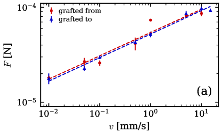
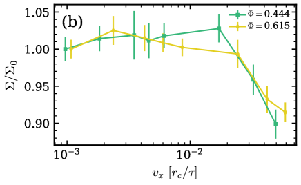
We first investigate the relation between the energy dissipation and the velocity of the droplet relative to the substrate. Experimentally, this is measured by imposing a constant substrate velocity while keeping the droplet in place by a cantilever, and measuring the force on the cantilever 54 (see Section ”Experimental Setup” above). The measured force corresponds to the friction force felt by the droplet. Once the force is measured, the power dissipated is calculated as . In the experiments, the force was measured for different velocities for droplets deposited on PDMS brushes synthesized using two different methods as described earlier: ”grafting from” and ”grafting to”. The ”grafting to” samples were washed after synthesis to remove free chains, while the ”grafting from” samples were not washed. The results from the experiments are shown in Figure 1. The force measurements on both samples seem to coincide and show very little effect of the synthesis method. One factor that would influence the friction force is the presence of free chains which would act as lubricant. Since the ”grafting to” samples were washed, no lubricant should be present 42. The experimental measurements then imply: either the ”grafting from” method does not leave residual free chains, the amount of free chains in PDMS polymer brushes was insufficient to reduce drop friction, or free chains hardly lower friction. The latter would mean that the addition of a small amount of free chains will only swell the brush and not make the interface more liquid-like, hence not lowering drop friction. On the other hand, it has been demonstrated in Reference 42 that free chains in a brush reduce the contact angle hysteresis, which is directly proportional to the friction force. Since it is difficult to control the amount of free chains in PDMS brushes experimentally, we turn to the simulations to investigate the effect of free chains on drop friction in a controlled fashion.
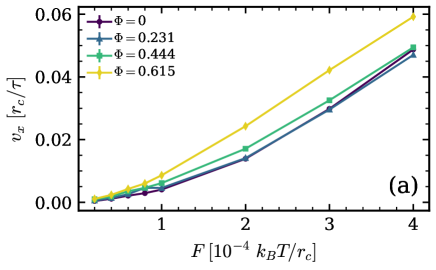
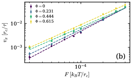
In the simulations, we apply a constant force to each of the liquid particles and measure the ensuing steady-state velocity . The velocity is taken as the mean x-component of the velocity of all liquid particles. The simulations were performed at varying fractions of free chains , giving brushes that are partly swollen by free chains, but not yet fully saturated (the saturation point is )59. For each fraction , forces ranging from to are applied on the liquid particles. For forces lower than the droplet does not seem to move. For forces higher than the droplet smears on the brush and forms a ”rivulet” across the periodic boundary. Figure 2 shows the steady-state velocity versus the force in linear (a) and logarithmic (b) representation. Looking at the trend lines, the velocity measurements for the lower free chain fractions essentially coincide, whereas the velocity at the same force increases for and again for , implying that the free chains indeed reduce the friction between the droplet and the substrate. Interestingly, this qualitative change of behavior coincides with the cloaking transition, which was located at in this system59: is just above the cloaking transition, and the droplets are not cloaked for the lower fractions. The trends in Figure 2 b) suggest a power law with exponents ranging between for bare droplets on dry brushes to for cloaked droplets on lubricated brushes.
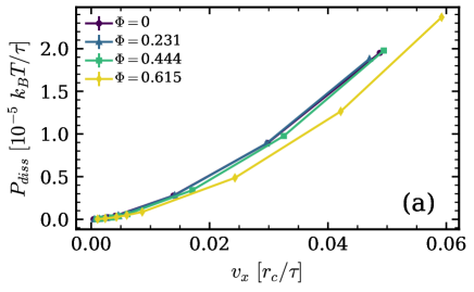
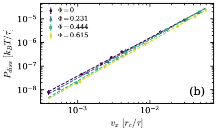
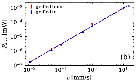
Another way of looking at the data is to calculate the power dissipated by the droplet. This can be done like in the experiments using . Figure 3 shows the steady-state power dissipation versus the steady-state velocity with linear axes in (a) and logarithmic in (b). This graph demonstrates again that the dissipated power is lower for higher lubrication (beyond the cloaking transition). The logarithmic plot also suggests a power law relation with exponents in the range of for droplets on dry brushes to for cloaked droplets.
The power law exponents in experiment and simulation are not the same. We will discuss this further below. One interesting aspect is that the presence of a small amount of free chains has no significant effect on the friction force acting on the droplet. This suggests that the quantity of free chains in the ”grafting from” method may not be large enough to lubricate the motion of the droplet. Beyond the cloaking transition, the friction between the droplets and the substrate is somewhat reduced. However, even this effect is comparatively small. As mentioned above, the total friction has contributions from multiple sources. Below, we quantify the response of the substrate and the flow within the droplet to better understand the small dependence of the friction force on lubrication.
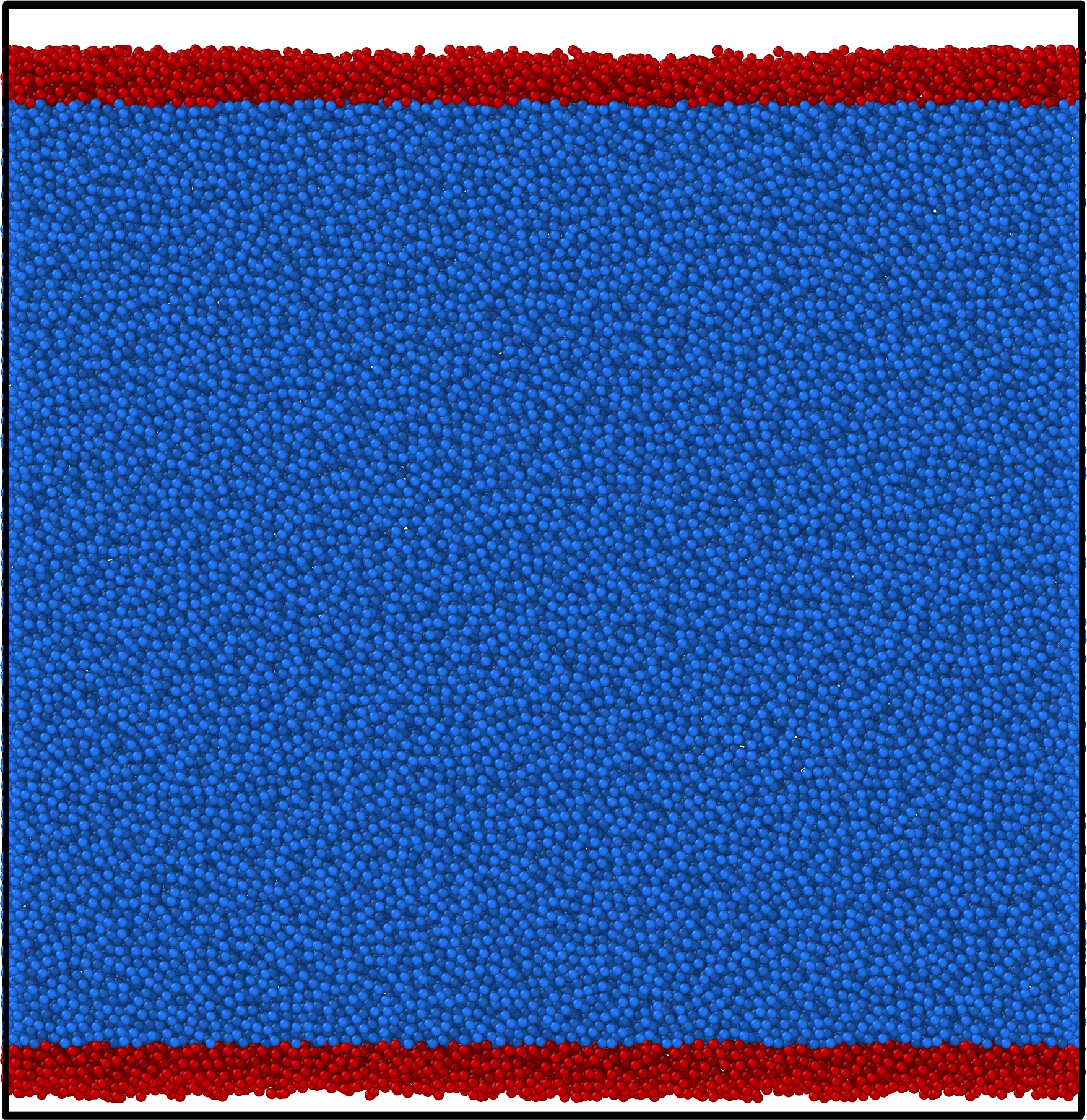
3.2 Droplet Shape and Contact Angles
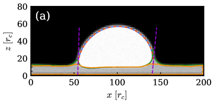
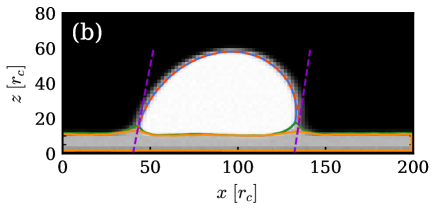
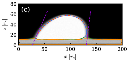
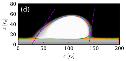
As the droplet slides, the forces acting on it cause it to deform, and at steady-state the shape of the droplet can be approximated by an ellipse. In addition, the advancing and receding contact angles differ from each other due to the adhesion of the droplet to the substrate. In order to characterize these effects, we take a section of the droplet of thickness along a plane parallel to the direction of motion and analyze the density map in that plane. Examples of such density maps are shown in Figure 4. From the density maps we delimit the different interfaces as density isosurfaces. The droplet surface (blue lines in Figure 4) corresponds to the water density isosurface , and the full substrate surface (green lines) to the polymer density isosurface (brush and free chains). These isosurfaces (or density contours) were set at densities corresponding to roughly half the bulk density of water and polymer. The brush surface (orange lines) is taken to be the brush monomer isosurface , where is the mean brush density and depends on the level of lubrication. Having determined the droplet surface, we can now fit the droplet-vapor part to a tilted ellipse. This is achieved by optimizing the coordinates of the foci and such that they best obey the relation , with a point on the droplet-vapor part of the contour, and the semi-major axis of the ellipse. The parameters , , and fully define the ellipse, and we can calculate contact angles at the advancing and receding ends. For this, we find the intersection of the ellipse with the horizontal line at the level of the unperturbed substrate and calculate the angle between the tangent to the ellipse at that point and the horizontal line. With this approach, we measure apparent, macroscopic, contact angles. In Figure 4, the ellipse and both the receding and advancing tangents are shown in red and purple dashed lines respectively. The ellipse fits the droplet quite well for all velocities at the receding end. However, right at the advancing front, the fit deviates significantly from the contour of the droplet. Thus the values of macroscopic advancing contact angles differ from the microscopic values. Unfortunately, it is difficult to unambiguously define microscopic contact angles in the presence of a wetting ridge, especially if the free chains spread on the droplet. Therefore, we limit our analysis to macroscopic contact angles.
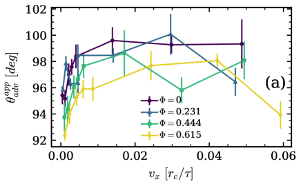
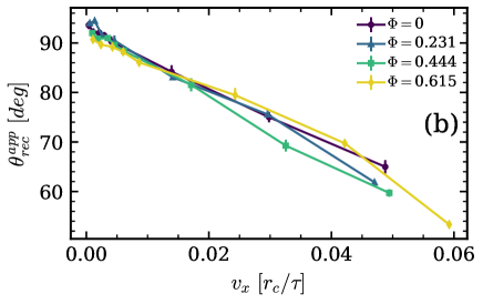
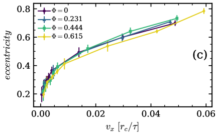
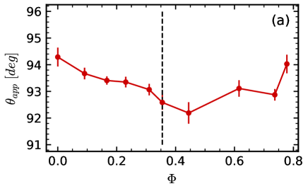
Figure 5 a) shows the apparent advancing contact angle versus velocity for different fractions of free chains. The shape of the curves is similar to that found in earlier experiments on expanding water drops on PDMS surfaces83: After an initial increase, the advancing contact angle quickly saturates, and it overall varies by less than ten degrees. In contrast, the receding contact angle , shown in Figure 5 b), decreases seemingly linearly as the velocity increases and drops to roughly 2/3 of the force-free value at the highest force. Along with this decrease of , the eccentricity of the ellipse strongly increases with velocity (Figure 5 c). However, all three quantities, i.e., the advancing and receding contact angles and the eccentricity, are not significantly affected by the presence of lubricant. This is already observed in equilibrium droplets: The equilibrium contact angles for different lubricant fractions are shown in Figure S.1 in the Supplementary Information. For all lubricant fractions we find an apparent angle .
3.3 The Wetting Ridge
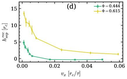
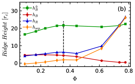
Next we study the influence of the moving droplet on the brush. The droplet pulls up on the brush at the three-phase contact line, due to the interfacial tension. Beyond the cloaking transition, the wetting ridge separates into two ”phases”. One phase still includes the brush chains, and the other is purely composed of free chains. A similar phase separation has also been observed for swollen PDMS gels 84, 36, 37. To quantify the effect of the moving droplet on the brush, we measure how the heights of the brush and the full ridge (brush and free chains) at the three-phase contact line vary with the velocity of the moving droplet. The heights are calculated as the highest points in the contours shown in Figure 4, measured from the grafting surface, both for the brush and the full substrate, and both for the receding end and the advancing front. In addition, a quantity of interest that has been studied in experiments is the separation height between the two phases 37. It is calculated as the difference between the brush height and the height reached by the free chains. Since no separation is observed below the cloaking transition, we can only calculate the separation height for the two densities and .
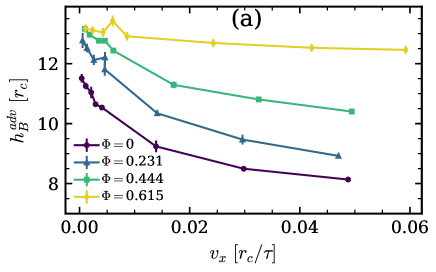
Figure 6 a) shows the height of the brush at the advancing front versus the steady state velocity of the droplet. The brush height at the advancing front always decreases with increasing velocity. The decrease is less pronounced for high swelling. This is due to the fact that the more the brush is swollen by lubricant, the less it is affected by the presence of the droplet, as can be seen in Figure S.1 b) in the Supplementary Information. This observation has implications for the contribution of the brush to the total friction force on the droplet: as the droplet moves, it pulls the brush at the advancing front. The further out the brush is pulled, the larger the viscoelastic dissipation within the brush.
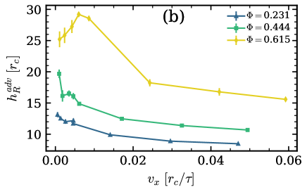
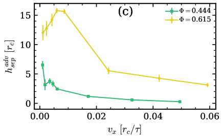
Figure 6 b) shows the height of the full ridge at the advancing front versus the steady state velocity of the droplet. For low lubrication, the ridge height decreases as the speed of the droplet increases. However, for something interesting happens: With increasing droplet velocity, the ridge height first increases up to a maximum at , then it starts decreasing again. Figure 6 c) shows the separation height at the advancing front versus the steady state velocity of the droplet. For and within the confidence intervals, the trend follows the expected decrease with velocity, while for the trend mirrors that of the ridge height . Finally, Figure 6 d) shows the separation height at the receding end versus the steady state velocity of the droplet. The separation between the brush and the liquid ridge at the receding end gradually decreases as the velocity of the droplet increases.
The peculiar behavior at the advancing front could be explained as follows. As the droplet rolls, it drags material from the receding end onto the advancing front. The material is transported as part of the cloak. For all velocities, material is depleted from the receding end, hence the separation height decreases. At the advancing front, however, material will be deposited. At low velocities, the material is deposited there and the ridge grows, leading to an increase in the separation height. This is the case until a threshold velocity is reached. Then the droplet starts rolling over the advancing ridge leading to a decrease in the separation height.
3.4 Flow Field
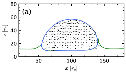
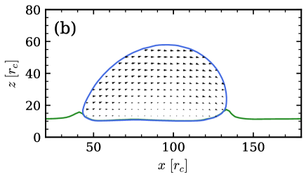
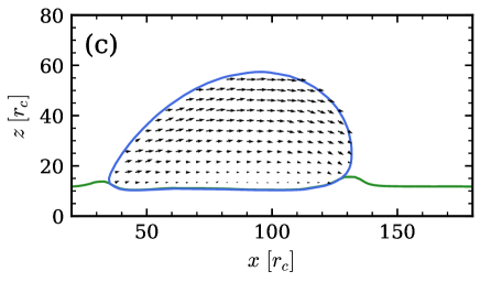
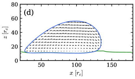
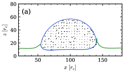
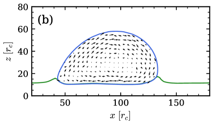
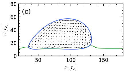
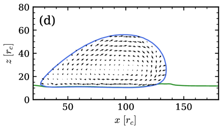
To understand the origin of the friction, we need to know whether the drop is rolling, sliding, or a combination of both. To answer this we calculate the flow field within the droplet. Figure 7 shows the flow field in the laboratory frame for a selection of forces. As above, we select a slab of the droplet of thickness along a plane parallel to the direction of motion and analyze the flow in this slab. To obtain the final flow fields we calculate a flow field from each simulation by taking an average over 150 snapshots, and subsequently average the flow fields of 5 independent simulations. For (Figure 7 a), the average local flow is smaller than the statistical error due to thermal motion within the droplet, hence flow profiles are not discernible. For the other forces in (b), (c), and (d) respectively, there is a clear net flow toward the right. At the interface between the droplet and the brush, the velocity is small indicating that the droplet rolls with little to no sliding even in the presence of lubricant. This is different from previous simulations of polymer droplets on hard corrugated substrates57, where significant slip was observed at the surface.
Figure 8 shows the flow field in the co-moving frame of the center of mass of the droplet. Again, extracting a flow field is not possible at the lowest force due to the random thermal motion. For stronger forces, the flow field profiles clearly feature a rolling motion. Interestingly, the flow field inside the droplet seems to feature two vortices, one close to the center of the droplet and one towards the back end. Similar two-vortex structures have been visualized experimentally in flow profiles inside adhering droplets in shear flow 85. Numerical Lattice Boltzmann simulations of rolling droplets on flat and structured hydrophobic surfaces have also revealed complex flow patterns inside the droplets 86.
3.5 Cloak Structure and Oil Transport
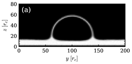
As real cloaked droplets move on PDMS substrates, they carry the lubricant with them, thus depleting the lubricant and reducing the associated favorable qualities of the substrate. To investigate the effect of the droplet motion on its cloak, we study how the cloak thickness is affected by the droplet velocity. We now section the droplet along a plane perpendicular to the direction of motion. We choose a section centered at the center of mass of the droplet and of thickness and calculate the local density of polymers within that section. Such a density map is shown in Figure 9 a). To measure the variation in the cloak we calculate an effective surface density at the top of the droplet
| (9) |
with corresponding to a point within the droplet, and a point above the cloak. Figure 9 b) shows versus the droplet velocity normalized by the value at the lowest velocity . For low velocities the cloak is not affected, but for the highest two velocities the value slightly decreases by about .
The fact that the cloaking layer is not strongly affected by the motion, combined with the fact that the area of the droplet increases at larger velocities due to shape deformations, implies that the transport of lubricant is expected to be enhanced at higher velocities.
4 Summary and Conclusion
In sum, we have studied the effect of adding lubricant on the motion of droplets on polymer brush coated surfaces under the influence of an external, e.g., gravitational, body force. The simulation model is adapted to describe water droplets on surfaces with PDMS brushes and free PDMS chains acting as lubricant. One characteristic of this system is the existence of a cloaking transition 59: beyond a critical lubricant content, the water droplet is fully covered by a thin layer of free PDMS chains. Hence our study also addresses the question how such a cloaking layer affects the droplet motion.
In general, we find that the droplet velocity increases with the applied force following a power law, . With increasing velocity, the droplet deforms and elongates. The receding contact angle decreases roughly linearly as a function of , while the advancing angle remains roughly constant.
Within the investigated amounts, lubrication has a surprisingly small effect on this behavior. Adding a limited amount of lubricant chains only slightly reduces the friction force between the droplet and the surface. This is already suggested indirectly by the experiments, where it was found that the friction does not depend on the method used to prepare the polymer brushes. In particular, whether or not free polymers have been washed out from the brushes after synthesis did not seem to make any difference. However, the degree of swelling could not be determined in the experiments. In the simulations, the velocity of droplets subject to a given driving force does not change at all (within the statistical error) if one adds lubricant amounts below the cloaking transition. Above the cloaking transition, the velocity somewhat increases, i.e., the friction is somewhat reduced, but by less than a factor 3/4 at the highest lubricant content. The power law exponent increases slightly for cloaked droplets, but by less than 20%.
Lubricants also have no discernible effect on the macroscopic properties of the droplet, i.e., its shape as a function of velocity, and the advancing and receding contact angles. They do however affect the local structure at the contact line, i.e., the wetting ridge. In particular, the ridge height of strongly cloaked droplets exhibits a maximum as a function of droplet velocity, suggesting a transition between a low-velocity regime where the droplet pushes the wetting ridge in front of it, to a regime where it partially rolls over it.
The reason for the unexpected low lubricating effect of free chains in the brush becomes clear when analyzing the pattern of the flow field inside the droplet. The friction results from an interplay of energy dissipation at the adhesive surface, at the contact line (the wetting ridge), and inside the droplet. In our system, we find that the flow velocity is very small at the interface between droplet and substrate, thus the droplet does not slide, and the dissipation at the adhesive surface can be neglected. The dissipation at the wetting ridge does contribute - as can be inferred from the fact that the friction force is affected by the cloaking transition, but this contribution seems to be comparatively small. We then argue that the dominating contribution to dissipation is the shear flow inside the droplet, which is not affected by the lubricant. For droplets of fixed shape with fixed flow patterns, one would expect the resulting friction force to scale linearly with the droplet velocity57. However, the droplets can partly reduce the dissipation at high velocities by changing their shape, which affects the flow profiles as discussed in Section ”Flow Field”. As a result, the increase of the friction force with droplet velocity is only sublinear.
The question remains why the power exponent measured in the simulations () differs from the one measured in the experiments (). Although we have studied large droplets containing almost a million particles, they are still microscopic compared to the droplets considered in the experiments, which have sizes of the orders of millimeters. Nevertheless, the Reynolds numbers in the simulations and experiments are comparable ( in the simulations for velocity and droplet radius , and in the experiments for mm/s and mm), suggesting that the flow fields may also be comparable. On the other hand, the experimental drop sizes are comparable to the capillary length such that gravity may become important. The influence of droplet size and gravity on the friction force will be an interesting subject of future studies.
We should also note that, in the present study, we have only studied lubricant fractions where the brush is not yet fully saturated. If we had much more lubricant, it will form a thick film above the brush, and the situation will change. The droplet will then be immersed in the lubricant film and the shear flow inside the film will significantly contribute to the dissipation.
5 Acknowledgments
This work was funded by the German Science Foundation (DFG) within the priority program SPP 2171 (Grant No. 422796905, projects Schm 985/22 and VO 639/16). Further support is acknowledged from the DFG-funded Graduate School RTG 2516 (Grant No. 405552959): RGBM and LH are associated members, FS is a member. The simulations were partly carried out on the supercomputer system Mogon NHR Süd-West at Johannes Gutenberg University Mainz. RGMB thanks Leonid Klushin for useful discussions.
References
- Brutin and Starov 2018 Brutin, D.; Starov, V. Recent advances in droplet wetting and evaporation. Chemical Society Reviews 2018, 47, 558–585
- Wang et al. 2022 Wang, Z.; Orejon, D.; Takata, Y.; Sefiane, K. Wetting and evaporation of multicomponent droplets. Phys. Rep. 2022, 960, 1–37
- Bertrand et al. 2002 Bertrand, E.; Bonn, D.; Broseta, D.; Dobbs, H.; Indekeu, J.; Meunier, J.; Ragil, K.; Shahidzadeh, N. Wetting of alkanes on water. Journal of Petroleum Science and Engineering 2002, 33, 217–222
- Wong et al. 2011 Wong, T.-S.; Kang, S. H.; Tang, S. K.; Smythe, E. J.; Hatton, B. D.; Grinthal, A.; Aizenberg, J. Bioinspired self-repairing slippery surfaces with pressure-stable omniphobicity. Nature 2011, 477, 443–447
- Lafuma and Quéré 2003 Lafuma, A.; Quéré, D. Superhydrophobic states. Nature materials 2003, 2, 457–460
- Schellenberger et al. 2015 Schellenberger, F.; Xie, J.; Encinas, N.; Hardy, A.; Klapper, M.; Papadopoulos, P.; Butt, H.-J.; Vollmer, D. Direct observation of drops on slippery lubricant-infused surfaces. Soft Matter 2015, 11, 7617–7626
- Wong et al. 2021 Wong, W. S.; Naga, A.; Hauer, L.; Baumli, P.; Bauer, H.; Hegner, K. I.; D’Acunzi, M.; Kaltbeitzel, A.; Butt, H.-J.; Vollmer, D. Super liquid repellent surfaces for anti-foaming and froth management. Nature communications 2021, 12, 1–11
- Blossey 2003 Blossey, R. Self-cleaning surfaces—virtual realities. Nature materials 2003, 2, 301–306
- Nakajima et al. 2000 Nakajima, A.; Hashimoto, K.; Watanabe, T.; Takai, K.; Yamauchi, G.; Fujishima, A. Transparent superhydrophobic thin films with self-cleaning properties. Langmuir 2000, 16, 7044–7047
- Parkin and Palgrave 2005 Parkin, I. P.; Palgrave, R. G. Self-cleaning coatings. Journal of materials chemistry 2005, 15, 1689–1695
- Tejero-Martin et al. 2019 Tejero-Martin, D.; Rad, M. R.; McDonald, A.; Hussain, T. Beyond Traditional Coatings: A Review on Thermal-Sprayed Functional and Smart Coatings. Journal of Thermal Spray Technology 2019, 28, 598–644
- Bergeron et al. 2000 Bergeron, V.; Bonn, D.; Martin, J. Y.; Vovelle, L. Controlling droplet deposition with polymer additives. Nature 2000, 405, 772–775
- Gaume et al. 2002 Gaume, L.; Gorb, S.; Rowe, N. Function of epidermal surfaces in the trapping efficiency of Nepenthes alata pitchers. New Phytologist 2002, 156, 479–489
- Choi et al. 2012 Choi, K.; Ng, A. H. C.; Fobel, R.; Wheeler, a. R. In Annual Review of Analytical Chemistry, Vol. 5; Cooks, R., Yeung, E., Eds.; Annual Review of Analytical Chemistry; 2012; Vol. 5; pp 413–440
- Cho et al. 2017 Cho, H. J.; Preston, D. J.; Zhu, Y.; Wang, E. N. Nanoengineered materials for liquid-vapour phase-change heat transfer. Nature Review Materials 2017, 2
- Rothstein 2010 Rothstein, J. P. Slip on Superhydrophobic Surfaces. Annual Review of Fluid Mechanics 2010, 42, 89–109
- Lee et al. 2016 Lee, C.; Choi, C.-H.; Kim, C.-J. Superhydrophobic drag reduction in laminar flows: a critical review. Experiments in Fluids 2016, 57
- Park et al. 2021 Park, H.; Choi, C.-H.; Kim, C.-J. Superhydrophobic drag reduction in turbulent flows: a critical review. Experiments in Fluids 2021, 62
- Xu et al. 2008 Xu, Q. F.; Wang, J. N.; Smith, I. H.; Sanderson, K. D. Directing the transportation of a water droplet on a patterned superhydrophobic surface. Applied Physics Letters 2008, 93
- Liu et al. 2010 Liu, X.; Ye, Q.; Yu, B.; Liang, Y.; Liu, W.; Zhou, F. Switching Water Droplet Adhesion Using Responsive Polymer Brushes. Langmuir 2010, 26, 12377–12382
- Liu et al. 2011 Liu, X.; Cai, M.; Liang, Y.; Zhou, F.; Liu, W. Photo-regulated stick-slip switch of water droplet mobility. Soft Matter 2011, 7, 3331–3336
- Karpitschka et al. 2015 Karpitschka, S.; Das, S.; van Gorcum, M.; Perrin, H.; Andreotti, B.; Snoeijer, J. H. Droplets move over viscoelastic substrates by surfing a ridge. Nature communications 2015, 6, 1–7
- Karpitschka et al. 2016 Karpitschka, S.; Pandey, A.; Lubbers, L. A.; Weijs, J. H.; Botto, L.; Das, S.; Andreotti, B.; Snoeijer, J. H. Liquid drops attract or repel by the inverted Cheerios effect. PNAS 2016, 113, 7403–7407
- Lee et al. 2016 Lee, H.; Lee, W.; Han, Y. S.; Kim, E.; Ryu, D. Y. Autophobic dewetting of polystyrenes on the substrates grafted with chemically identical polymers. Polymer Journal 2016, 48, 503–507
- Okada et al. 2020 Okada, K.; Miura, Y.; Chiya, T.; Tokudome, Y.; Takahashi, M. Thermo-responsive wettability surface roughness change on polymer-coated titanate nanorod brushes toward fast and multi-directional droplet transport. RSC Advances 2020, 10, 28032–28036
- Khatir et al. 2023 Khatir, B.; Dijvejin, Z. A.; Serles, P.; Filleter, T.; Golovin, K. Molecularly Capped Omniphobic Polydimethylsiloxane Brushes with Ultra-Fast Contact Line Dynamics. Small 2023, 19
- Kajouri et al. 2023 Kajouri, R.; Theodorakis, P. E.; Zidek, J.; Milchev, A. Antidurotaxis Droplet Motion onto Gradient Brush Substrates. Langmuir 2023, 39, 15285–15296
- Kajouri et al. 2023 Kajouri, R.; Theodorakis, P. E.; Deuar, P.; Bennacer, R.; Zidek, J.; Egorov, S. A.; Milchev, A. Unidirectional Droplet Propulsion onto Gradient Brushes without External Energy Supply. Langmuir 2023,
- Weijs et al. 2011 Weijs, J. H.; Marchand, A.; Andreotti, B.; Lohse, D.; Snoeijer, J. H. Origin of line tension for a Lennard-Jones nanodroplet. Physics of fluids 2011, 23, 022001
- Weijs et al. 2014 Weijs, J. H.; Snoeijer, J. H.; Andreotti, B. Capillarity of soft amorphous solids: A microscopic model for surface stress. Phys. Rev. E 2014, 89
- Andreotti and Snoeijer 2016 Andreotti, B.; Snoeijer, J. H. Soft wetting and the Shuttleworth effect, at the crossroads between thermodynamics and mechanics. EPL 2016, 113
- Andreotti and Snoeijer 2020 Andreotti, B.; Snoeijer, J. H. In Annual Review of Fluid Mechanics; Davis, S., Moin, P., Eds.; Annual Review of Fluid Mechanics; 2020; Vol. 52; pp 285–308
- Daniel et al. 2020 Daniel, D.; Florida, Y.; Lay, C. L.; Koh, X. Q.; Sng, A.; Tomczak, N. Quantifying Surface Wetting Properties Using Droplet Probe Atomic Force Microscopy. ACS Appl. Materials & Interfaces 2020, 12, 42386–42392
- Peschka 2018 Peschka, D. Variational approach to dynamic contact angles for thin films. Physics of Fluids 2018, 30
- Giacomelli et al. 2023 Giacomelli, L.; Gnann, M. V.; Peschka, D. Droplet motion with contact-line friction: long-time asymptotics in complete wetting. Proc. Royal Soc. A 2023, 479
- Cai et al. 2021 Cai, Z.; Skabeev, A.; Morozova, S.; Pham, J. T. Fluid separation and network deformation in wetting of soft and swollen surfaces. Communications Materials 2021, 2, 1–11
- Hauer et al. 2023 Hauer, L.; Cai, Z.; Skabeev, A.; Vollmer, D.; Pham, J. T. Phase separation in wetting ridges of sliding drops on soft and swollen surfaces. Physical Review Letters 2023, 130, 058205
- Wang and McCarthy 2016 Wang, L.; McCarthy, T. J. Covalently attached liquids: instant omniphobic surfaces with unprecedented repellency. Angewandte Chemie International Edition 2016, 55, 244–248
- Chen et al. 2023 Chen, L.; Huang, S.; Ras, R. H.; Tian, X. Omniphobic liquid-like surfaces. Nature Reviews Chemistry 2023, 7, 123–137
- Zhao et al. 2021 Zhao, X.; Khatir, B.; Mirshahidi, K.; Yu, K.; Kizhakkedathu, J. N.; Golovin, K. Macroscopic evidence of the liquidlike nature of nanoscale polydimethylsiloxane brushes. ACS nano 2021, 15, 13559–13567
- Wooh and Vollmer 2016 Wooh, S.; Vollmer, D. Silicone brushes: omniphobic surfaces with low sliding angles. Angewandte Chemie International Edition 2016, 55, 6822–6824
- Teisala et al. 2020 Teisala, H.; Baumli, P.; Weber, S. A.; Vollmer, D.; Butt, H.-J. Grafting silicone at room temperature—a transparent, scratch-resistant nonstick molecular coating. Langmuir 2020, 36, 4416–4431
- Shanahan and Carre 1994 Shanahan, M.; Carre, A. Anomalous spreading of liquid drops on an elastomeric surface. Langmuir 1994, 10, 1647–1649
- Shanahan and Carre 1995 Shanahan, M.; Carre, A. Viscoelastic dissipation in wetting and adhesion phenomena. Langmuir 1995, 11, 1396–1402
- Long et al. 1996 Long, D.; Ajdari, A.; Leibler, L. Static and dynamic wetting properties of thin rubber films. Langmuir 1996, 12, 5221–5230
- Roy et al. 2020 Roy, R.; Seiler, R. L.; Weibel, J. A.; Garimella, S. V. Droplets on Soft Surfaces Exhibit a Reluctance to Coalesce due to an Intervening Wetting Ridge. Advanced Materials Interfaces 2020, 7
- Bico et al. 2018 Bico, J.; Reyssat, É.; Roman, B. Elastocapillarity: When surface tension deforms elastic solids. Annual Review of Fluid Mechanics 2018, 50, 629–659
- Zhao et al. 2018 Zhao, M.; Dervaux, J.; Narita, T.; Lequeux, F.; Limat, L.; Roché, M. Geometrical control of dissipation during the spreading of liquids on soft solids. Proceedings of the National Academy of Sciences 2018, 115, 1748–1753
- Sadullah et al. 2018 Sadullah, M. S.; Semprebon, C.; Kusumaatmaja, H. Drop dynamics on liquid-infused surfaces: The role of the lubricant ridge. Langmuir 2018, 34, 8112–8118
- Smith et al. 2013 Smith, J. D.; Dhiman, R.; Anand, S.; Reza-Garduno, E.; Cohen, R. E.; McKinley, G. H.; Varanasi, K. K. Droplet mobility on lubricant-impregnated surfaces. Soft Matter 2013, 9, 1772–1780
- Daniel et al. 2017 Daniel, D.; Timonen, J. V.; Li, R.; Velling, S. J.; Aizenberg, J. Oleoplaning droplets on lubricated surfaces. Nature Physics 2017, 13, 1020–1025
- Kreder et al. 2018 Kreder, M. J.; Daniel, D.; Tetreault, A.; Cao, Z.; Lemaire, B.; Timonen, J. V.; Aizenberg, J. Film dynamics and lubricant depletion by droplets moving on lubricated surfaces. Physical Review X 2018, 8, 031053
- Hourlier-Fargette et al. 2018 Hourlier-Fargette, A.; Dervaux, J.; Antkowiak, A.; Neukirch, S. Extraction of silicone uncrosslinked chains at air–water–polydimethylsiloxane triple lines. Langmuir 2018, 34, 12244–12250
- Naga et al. 2021 Naga, A.; Kaltbeitzel, A.; Wong, W. S.; Hauer, L.; Butt, H.-J.; Vollmer, D. How a water drop removes a particle from a hydrophobic surface. Soft Matter 2021, 17, 1746–1755
- Jeon et al. 2023 Jeon, H.; Chao, Y.; Karpitschka, S. Moving wetting ridges on ultrasoft gels. Physical Review E 2023, 108, 024611
- Thampi et al. 2013 Thampi, S. P.; Adhikari, R.; Govindarajan, R. Do liquid drops roll or slide on inclined surfaces? Langmuir 2013, 29, 3339–3346
- Servantie and Müller 2008 Servantie, J.; Müller, M. Statics and dynamics of a cylindrical droplet under an external body force. The Journal of chemical physics 2008, 128
- Léonforte and Müller 2011 Léonforte, F.; Müller, M. Statics of polymer droplets on deformable surfaces. The Journal of chemical physics 2011, 135, 214703
- Badr et al. 2022 Badr, R. G.; Hauer, L.; Vollmer, D.; Schmid, F. Cloaking transition of droplets on lubricated brushes. The Journal of Physical Chemistry B 2022, 126, 7047–7058
- Cao and Dobrynin 2015 Cao, Z.; Dobrynin, A. V. Polymeric Droplets on Soft Surfaces: From Neumann’s Triangle to Young’s Law. Macromolecules 2015, 48, 443–451
- Mensink et al. 2019 Mensink, L. I.; Snoeijer, J. H.; De Beer, S. Wetting of polymer brushes by polymeric nanodroplets. Macromolecules 2019, 52, 2015–2020
- Mensink et al. 2021 Mensink, L. I.; de Beer, S.; Snoeijer, J. H. The role of entropy in wetting of polymer brushes. Soft matter 2021, 17, 1368–1375
- Greve et al. 2023 Greve, D.; Hartmann, S.; Thiele, U. Stick-slip dynamics in the forced wetting of polymer brushes. Soft Matter 2023, 19, 4041–4061
- Kap et al. 2023 Kap, O.; Hartmann, S.; Hoek, H.; de Beer, S.; Siretanu, I.; Thiele, U.; Mugele, F. Nonequilibrium configurations of swelling polymer brush layers induced by spreading drops of weakly volatile oil. J. Chem. Phys. 2023, 158
- Speyer and Pastorino 2017 Speyer, K.; Pastorino, C. Droplet Transport in a Nanochannel Coated by Hydrophobic Semiflexible Polymer Brushes: The Effect of Chain Stiffness. Langmuir 2017, 33, 10753–10763
- Pastorino and Mueller 2021 Pastorino, C.; Mueller, M. Liquid and Droplet Transport in Brush-Coated Cylindrical Nanochannels: Brush-Assisted Droplet Formation. J. Phys. Chem. B 2021, 125, 442–449
- Leong and Le 2021 Leong, F. Y.; Le, D.-V. Dynamics of a droplet on a polymer brush in channel flow. Physics of Fluids 2021, 33
- Hoogerbrugge and Koelman 1992 Hoogerbrugge, P.; Koelman, J. Simulating microscopic hydrodynamic phenomena with dissipative particle dynamics. Europhysics letters 1992, 19, 155
- Espanol 1995 Espanol, P. Hydrodynamics from dissipative particle dynamics. Physical Review E 1995, 52, 1734
- Marsh et al. 1997 Marsh, C.; Backx, G.; Ernst, M. Static and dynamic properties of dissipative particle dynamics. Physical Review E 1997, 56, 1676
- Pagonabarraga and Frenkel 2001 Pagonabarraga, I.; Frenkel, D. Dissipative particle dynamics for interacting systems. The Journal of chemical physics 2001, 115, 5015–5026
- Trovimov et al. 2002 Trovimov, S.; Nies, E.; Michels, M. Thermodynamic consistency in dissipative particle dynamics simulations of strongly nonideal liquids and liquid mixtures. The Journal of chemical physics 2002, 117, 9383–9394
- Warren 2003 Warren, P. Vapor-liquid coexistence in many-body dissipative particle dynamics. Physical Review E 2003, 68, 066702
- Warren 2013 Warren, P. B. No-go theorem in many-body dissipative particle dynamics. Physical Review E 2013, 87, 045303
- Weeks et al. 1971 Weeks, J. D.; Chandler, D.; Andersen, H. C. Role of repulsive forces in determining the equilibrium structure of simple liquids. The Journal of chemical physics 1971, 54, 5237–5247
- Young 1805 Young, T. III. An essay on the cohesion of fluids. Philosophical transactions of the royal society of London 1805, 65–87
- Anderson et al. 2020 Anderson, J. A.; Glaser, J.; Glotzer, S. C. HOOMD-blue: A Python package for high-performance molecular dynamics and hard particle Monte Carlo simulations. Computational Materials Science 2020, 173, 109363
- Phillips et al. 2011 Phillips, C. L.; Anderson, J. A.; Glotzer, S. C. Pseudo-random number generation for Brownian Dynamics and Dissipative Particle Dynamics simulations on GPU devices. Journal of Computational Physics 2011, 230, 7191–7201
- Stukowski 2009 Stukowski, A. Visualization and analysis of atomistic simulation data with OVITO–the Open Visualization Tool. Modelling and simulation in materials science and engineering 2009, 18, 015012
- Zhao et al. 2020 Zhao, X.; Khandoker, M. A. R.; Golovin, K. Non-fluorinated omniphobic paper with ultralow contact angle hysteresis. ACS applied materials & interfaces 2020, 12, 15748–15756
- Hegner et al. 2023 Hegner, K. I.; Hinduja, C.; Butt, H.-J.; Vollmer, D. Fluorine-Free Super-Liquid-Repellent Surfaces: Pushing the Limits of PDMS. Nano Letters 2023, 23, 3116–3121
- Naga 2021 Naga, A. Capillary interactions in wetting: rotation of particles at interfaces and removal of particles by drops. Ph.D. thesis, Johannes Gutenberg-Universität Mainz, 2021
- William et al. 2020 William, S. Y. W.; Hauer, L.; Naga, A.; Kaltbeitzel, A.; Baumli, P.; Berger, R.; D’Acunzi, M.; Vollmer, D.; Butt, H.-J. Adaptive wetting of polydimethylsiloxane. Langmuir 2020, 36, 7236–7245
- Jensen et al. 2015 Jensen, K. E.; Sarfati, R.; Style, R. W.; Boltyanskiy, R.; Chakrabarti, A.; Chaudhury, M. K.; Dufresne, E. R. Wetting and phase separation in soft adhesion. Proceedings of the National Academy of Sciences 2015, 112, 14490–14494
- Burgmann et al. 2022 Burgmann, S.; Krämer, V.; Rohde, M.; Dues, M.; Janoske, U. Inner and outer flow of an adhering droplet in shear flow. International Journal of Multiphase Flow 2022, 153
- Abubakar et al. 2021 Abubakar, A. A.; Yilbas, B. S.; Al-Qahtani, H.; Mohammed, A. S. Droplet Rolling Dynamics over a Hydrophobic Surface with a Minute Width Channel. Langmuir 2021, 37, 7851–7861
6 Supplementary Information
6.1 Characteristics of equilibrium droplets
The surface tensions, the contact angle, and the properties of the wetting ridge in equilibrium droplets have been determined in previous work59. For the convenience of the reader, we reproduce some pertinent results in Figure S.1. Figure S.1 a) shows the macroscopic contact angle as a function of lubricant fraction and demonstrates that it stays almost constant. Figure S.1 b) characterizes the wetting ridge for varying in terms of the heights of the brush and the full ridge (brush and lubricant, ) at the three phase contact line, taking the unperturbed brush as a baseline. The curves for and demonstrate that the wetting ridge grows only slowly with increasing below the cloaking transition, but rises rapidly above the cloaking transition. Also shown in this figure is the absolute height of the brush (), measured with respect to the grafting surface. This quantity grows below the cloaking transition and then saturates at a value corresponding to the thickness of an unperturbed saturated brush () above the cloaking transition.
6.2 Poiseuille flow
In order to get an estimate of the viscosity, we set up Poiseuille flow simulations. We start with a liquid slab at equilibrium, fix some particles at the top and bottom (red particles in Figure S.2), and apply a constant force per particle to the other particles (blue particles in Figure S.2). The resulting flow profile has the form
| (S.1) |
with the dynamic viscosity, where is the force per particle, the number density and .
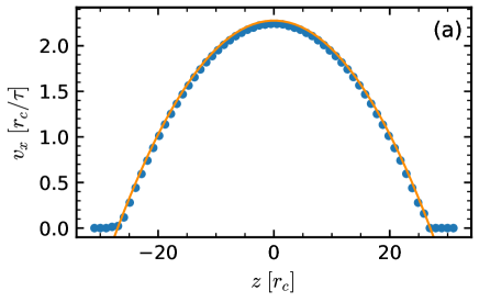
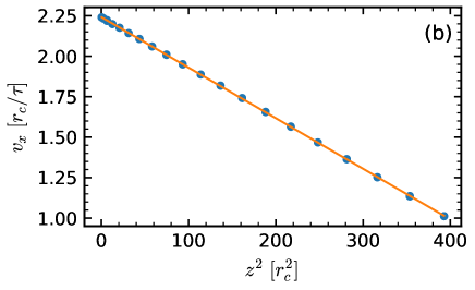
The flow for a force is shown in Figure S.3 a). The flow is parabolic as expected. To calculate the viscosity, we take velocity values for and use linear fitting to determine the parameters and of (see Figure S.3 (b) ). Then from the slope we calculate the dynamic viscosity . For the data shown in Figure S.3 we obtain .