1/f frequency fluctuations due to kinetic inductance in CoSi2 microwave cavities
Abstract
Cobalt disilicide provides a promising nearly-epitaxial superconducting material on silicon, which is compatible with high-density integrated circuit technology. We have characterized CoSi2 superconducting microwave cavities around \qty5.5GHz for resonance frequency fluctuations at temperatures \qtyrange[range-phrase = –,range-units = single]10200mK. We found relatively weak fluctuations following the spectral density , with and slightly below 1 at an average number of photons of ; the noise decreased with measurement power as . We identify the noise as arising from kinetic inductance fluctuations and discuss possible origins of such fluctuations.
I Introduction
Low noise materials working at microwave frequencies are essential for nano- and micro-fabrication of quantum circuits [1]. Besides the noise properties at low frequencies and microwave frequencies [2, 3, 4], compatibility with existing large scale integrated circuit technologies is an important issue for selection of future materials [5]. Unfortunately, proper understanding of microscopic noise mechanisms in the employed superconducting materials, such as aluminum, is not fully understood. There is, however, ample evidence that surfaces and interfaces act as important sources of noise. Consequently, epitaxial systems form an important class of materials whose potential has not yet been completely exhausted.
In this work, we characterize low frequency noise properties of one promising nearly-epitaxial material, cobalt dicilicide (CoSi2), as a platform for GHz frequency low-loss microwave cavities. Superconducting CoSi2 is a high-quality material that can be manufactured using a simple self-limiting process: a layer of cobalt of thickness is annealed on top of silicon, which yields a -thick CoSi2 conductor embedded into Si [6]. This embedded CoSi2 structure has an excellent lattice match to silicon. Owing to the nearly-epitaxial match, the CoSi2/Si interface is nearly defect-free, which results in an exceptionally low level of resistance noise [7].
Thin CoSi2 films possess a substantial kinetic inductance [8]. This inductance scales with normal state resistance, i.e. inversely with the cross-sectional area of the conductor. One of the questions that we aim to answer in our present work is whether the small resistance noise in the normal state turns into small noise in the kinetic inductance in the superconducting state, i.e. into ultra small fluctuations in the resonant frequency of a microwave cavity.
The resistance noise is due to parameter fluctuations [9] and it can be described in normal conductors as , where the power spectrum of current is denoted by at constant voltage bias, and . Basic models for noise can be found in Ref. [10, 11, 12] and summarized in Ref. [4]. Most often, noise models are based on the summation of an ensemble TLSs á la McWorther [13], but more involved theories based on impurity clustering have also been proposed [14, 15, 16].
In superconductors, the basic parametric variation is noise in kinetic inductance , which becomes prominent in metals and alloys that have a large normal state resistance, such as in thin CoSi2 films. In superconducting microwave cavities, besides fluctuations in , noise in the dielectric permittivity of the substrate leads to fluctuations in the resonant frequency. Customarily, these fluctuations in the cavity frequency are expected to arise from two level states (TLS) active around the resonant frequency [17, 2, 3]. Such low-frequency dielectric (or inductive) noise turns into time dependence of the circuit parameters leading to unwanted detuning of narrow band circuits, such as qubits connected to their read-out cavities. A generic feature of the TLS noise is the reduction of observed noise with increasing measurement power, typically as with .
Because fluctuations of the resonant frequency in our CoSi2 cavity are expected to be small, extra care was taken to avoid low frequency noise from the measurement system itself. We employed a Pound locking scheme as our starting point [18], which is known to avoid noise issues present in homodyne measurement setups. However, we did not use the setup in the closed loop (locked) regime, choosing instead to operate in the open loop regime, where it is easier to achieve a larger bandwidth. Moreover, as the overall drift is small in our samples, it is quite easy to remain in the linear error regime for extended periods without the need to adjust the operation frequency. In our Pound locking setup, the frequency fluctuations are obtained from the error voltage according to [19]
| (1) |
where and denote the power spectral density of and the fluctuating cavity frequency , respectively, and is the mean of the cavity resonant frequency. In the last form, refers to measurement power, and its influence is described by the exponent .
II Experimental methods
Our experimental setup is illustrated in Fig. 1. It is based on a standard Pound locking scheme operating at microwave frequencies. We have employed both closed loop and open loop operations. The experiments with feedback connected yielded equivalent results as the open loop configuration 111A drawback of our PID controller was that it gives non-constant intervals between the points. Consequently, Lomb-Scargle Periodogram analysis had to be performed instead of the regular Fast Fourier Transform. With such analysis, agreement between open and closed loop measurements was achieved.
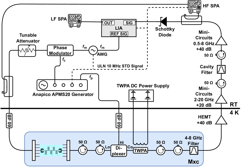
The cavity is connected through a six-port microwave switch and two circulators to a traveling wave amplifier based on SNAIL unit cells [21] and operating between \qtyrange[range-phrase = –,range-units = single]48GHz frequency band. The TWPA is rf pumped at a frequency around 11 GHz via a diplexer in which the other input port passes the signal frequency band from the cavity. The operating point was tuned to minimize the intermodulation products in the traveling wave parametric amplifier (TWPA) output signal by tuning the battery-driven flux bias [22]. The amplified signal from the cavity, after further RT amplification and filtering, is connected to a detection diode and to a microwave spectrum analyzer via a directional coupler, which we employ for signal monitoring purposes. The zero-bias Schottky diode detector (Krytar 203BK) is connected to an rf frequency lock-in amplifier (LIA, Stanford Research SR844) locked to the modulation frequency around 2 MHz from the arbitrary waveform generator (AWG, Agilent 33500B); this high modulation frequency, which eliminates problems with low frequency noise of typical homodyne detection schemes, is one of the attractive features of the Pound locking scheme. The LIA provides the error signal (see Eq. (3) below) that is analyzed using a low frequency spectrum analyser (Stanford Research SRS785).
In the open loop mode, the modulated drive signal, containing the carrier frequency () and side bands , with nearly equal voltage amplitudes, is produced using a high-quality microwave generator (XCO, Anapico APMS20) and the AWG. The modulation frequency is generated by the AWG, which drives the phase modulator unit (Minicircuits ZX05-83+) for generating the sidebands from the carrier signal of the XCO. The modulated signal is fed to the cavity through a programmable attenuator (Vaunix LDA-602) and a microwave switch. The time base of the AWG is locked to the 10 MHz reference signal derived from the XCO, which contains an Ultra Low Noise (ULN) reference option.
Our CoSi2 samples are notch-type cavities with five resonators coupled to a central read-out line [8]. Transmission for a notch type resonator with good phase and amplitude calibration can be written as [23, 24, 25]
| (2) |
where is the loaded quality factor, the quality factor related to the coupling to external circuit, quantifies impedance mismatch, the probing frequency, and denotes the normalized frequency shift from the resonance frequency . Employing open source fitting tools [26], it is found, that Eq. (2) agrees perfectly to our measured data as demonstrated in Ref. 8. The internal quality factor , in turn, can be obtained from the fitted values of and using . In our cavities with and 100 nm, fitting of Eq. (2) to the data indicates that coupling to external circuit is quite strong, and , while dominates in 10 nm CoSi2 films.
The voltage that enters the diode detector is a sum of three frequency components that have traveled through the notch-type resonator. Under symmetric side-band response, the phase response is given by an error signal of form 222 In the absence of phase shift between side band frequencies , the imaginary part is given by , while the real part is . Under symmetric sideband response, the real part vanishes and we are left with the error signal in the imaginary part.. Since , the error signal for side bands without phase shift can be approximated by
| (3) |
where terms of the order of and higher have been omitted. As seen from the second term on the right side of Eq. (3), impedance mismatch produces an offset in the error function. Therefore, the slope of the error function has to be recorded separately for all measurement conditions to verify the linear operation regime; is the conversion factor that converts measured noise to actual frequency fluctuations. In the error function measurements, the phase shift between frequencies and was adjusted approximately to \qty180 by tuning to a proper value. However, due to the impedance mismatch and as per the offset, the exact value isn’t simple to distinguish.
III Experimental results
The designed resonance frequency for the studied cavities with length \qtyrange[range-phrase = –,range-units = single]3.864.36mm was \qtyrange[range-phrase = –,range-units = single]6.837.73GHz. The actual measured resonance frequency for 25-nm-thick cavities was \qtyrange[range-phrase = –,range-units = single]5.215.88GHz, while the internal quality factors amounted to at base temperature of the cryostat \qty10mK. The nominal characteristic impedance of 25-nm samples was \qty50, but due to kinetic inductance, the actual value was closer to \qty65. The superconducting transition temperature was found to be at \qty[separate-uncertainty,separate-uncertainty-units = single]1.34(0.03)K, whereas the sheet resistances at 1.5 K were 7.1, 2.4, and \qty0.24 for the CoSi2 films with thicknesses of , 25, and 105 nm respectively. For further details, we refer to Ref. 8.
A few fits of the measured power spectra for frequency fluctuations at different temperatures between \qtyrange[range-phrase = –,range-units = single]20200mK are displayed in Fig. 2(a). The upper temperature limit of 200 mK was chosen as the cavity frequency became quite sensitive to temperatures owing to the strong temperature dependence of cavity frequency caused by the large kinetic inductance of the employed superconducting material. Consequently, the measured low frequency noise started having extra variation owing to variations in the temperature stability during the data collection period.
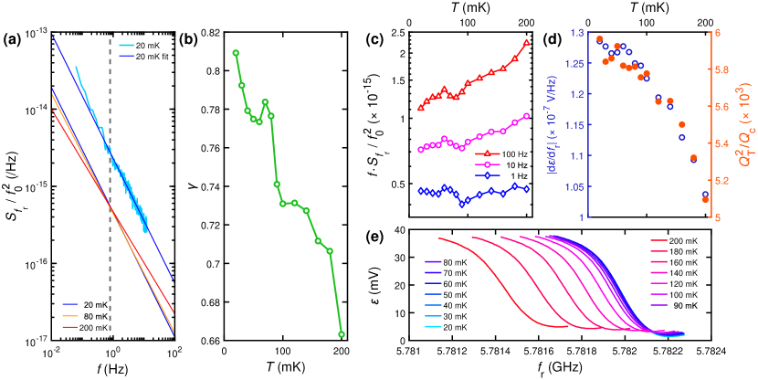
Several measured error curves of our notch-type resonator with nm are displayed in Fig. 2(e); the corresponding measured can be found in Ref. [8]. A large suppression of transmission at resonance indicates that this device is nearly critically coupled with . Because we are interested in noise at small power levels at the carrier frequency, our experiments were performed using a low-noise TWPA as a preamplifier [28]. Pound-locking-type modulation scheme in conjunction with the TWPA allowed us to measure noise efficiently at powers corresponding to quanta in the cavity. In the course of our experiments, we also investigated the noise induced by the TWPA [22]. We found that the operating point of the TWPA had to be carefully tuned to find a sweet operating spot for low noise performance [22].
The data in Fig. 2(a) were fit using Eq. (1) with and as free parameters (power is kept constant so that can be omitted here). The obtained noise exponent is displayed in Fig. 2(b) as a function of temperature. The data indicate clear temperature dependence in between 20 and 200 mK. The results on are similar to those obtained for flux noise in SQUIDs where magnetic impurities are supposed to dominate the noise [29].
Using the fit results for and , we find a pivot point for the noise traces at \qty[separate-uncertainty,separate-uncertainty-units = single]0.8(0.5)Hz (see Fig. 2(a)). Also, this pivoting feature is similar to findings in SQUIDs in Ref. 29. Fig. 2(c) depicts the noise power measured at 1, 10 and \qty100Hz from fitting to Eq. (1). Near the pivot point, the noise power presents no clear dependence on temperature while clear increase is seen at 10 Hz and 100 Hz.
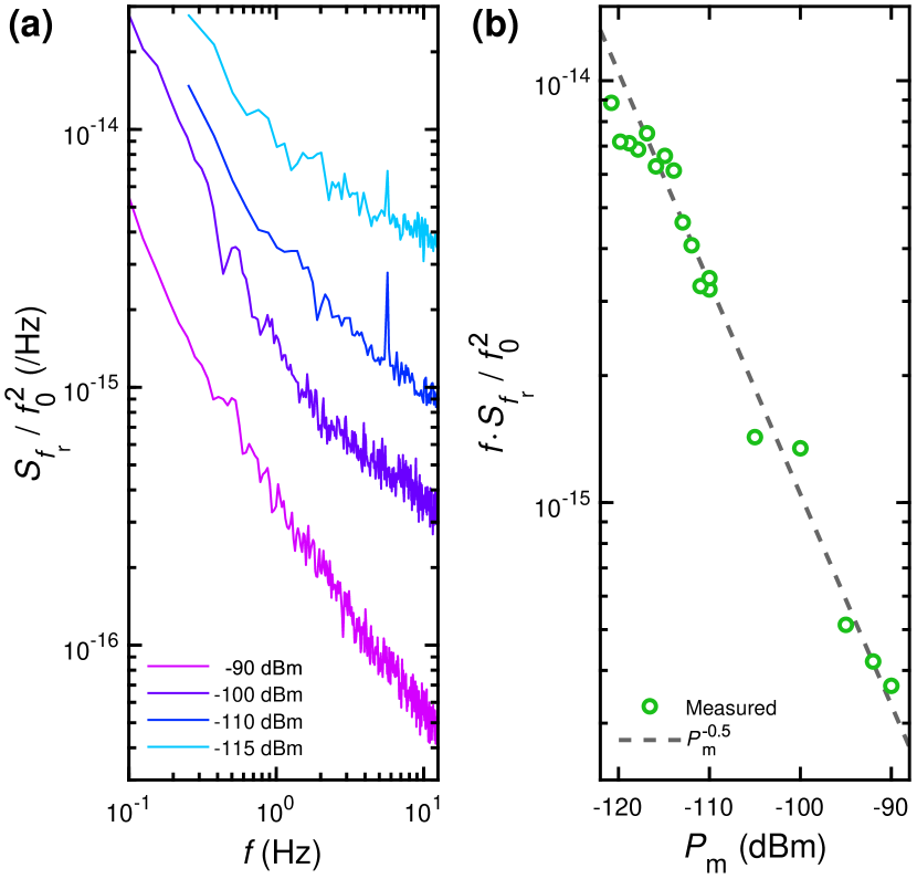
Frequency fluctuation spectra at different carrier powers are shown in Fig. 3(a). The noise spectra were averaged times, with the number of averages decreasing with increasing power. The largest measurement power \qty-90dBm yielded nearly type of noise while clear deviation due to white noise could be observed at smaller powers. In our measurements, the number of averages could be lowered with increasing because the thermal background noise was found to decrease as while the noise decayed slower with 333The enhanced white noise here from the detection circuitry is due to the chosen large dynamic range of the system with only rather small gain before the diode detector.. Fig. 3(b) displays the observed decrease in noise with increasing carrier power. dependence is clearly observed from to \qty-90dBm carrier power.
IV Discussion
Previous experiments have demonstrated that thin CoSi2 films possess a substantial temperature-dependent kinetic inductance [8]. These experiments yielded for temperature dependence of the cavity frequency \unitK^-4. At K, this corresponds to \unitK^-1, which yields Hz for one \unit\microK fluctuation 444Our resistance bridge reading display approximately \qty1\microK rms-noise at 1 Hz for the mixing chamber temperature. This noise, however, may be electronic in origin so it has to be considered as an upper limit estimate for temperature fluctuations.. Such a fluctuation corresponds to approximately 10% of the frequency fluctuations of 100 Hz observed at 1 Hz.
In SQUIDs, it has been argued that clusters of spins may dominate the flux noise. Ferromagnetic clustering could lead to large enough local fields that would yield time-varying dynamics of spins, interacting with the order parameter and with current-induced microwave flux, which could result in low frequency noise in the measured microwave transmission. Typically, flux noise due to such clustering spins influence dissipation in the microwave cavity, and they lead to a characteristic increase of as a function of drive power. Even though a complete microscopic model for the magnetic moments acting on the order parameter is missing, we may expect that a similar order parameter suppression may arise from the trapped flux present in our sample without magnetic shielding. Fluctuations in the order parameter lead to variation in kinetic inductance which is seen as frequency noise.
One way to estimate the expected inductance noise magnitude is to consider the cavity as a long weak link for which the critical current is related to the normal state resistance by the Ambegaokar-Baratoff formula: . For a wire, this can be taken as valid for a section with length equalling the coherence length, amounting to \qty90nm at zero temperature [32]. As the length of our cavities is around \qty4mm, \qty90nm means that the total kinetic inductance of \qty∼1nH is built from sections with inductance of \qty25fH. The critial current can be estimated using the equation for kinetic inductance [33, 34] which yields mA. As the sheet resistance \qty2.4, this supercurrent yields \qty0.1mV where \qty0.02 is the resistance over one coherence length. This value is close to the energy gap in CoSi2.
To estimate fluctuations, we need an approximate number of independent fluctuations in resistance. In CoSi2, resistance fluctuations at \qty1Hz amount to an exceptionally small value: [7]. This is independent of length as long as , the inelastic coherence, which can be microns \qty10\microm in normal metals at mK temperatures [35]. Thus, the resistance fluctuations can be considered to be built from sections with , which is reduced by , yielding for the whole length ; this gives a conservative estimate for the inductance noise. However, the number of independent inductive sections in the superconducting state contributing to may be even larger. Assuming as the basic independent unit, we obtain an even larger reduction in noise, resulting in an expectation value of . This would yield , which is well comparable with typical frequency fluctuations in microwave cavities, mostly induced by two-level systems modifying the dielectric properties of the substrate and the surface of the conductor [36]. Our result at small power is at \qty1Hz, which is close to the upper estimate based on the normal-state resistance noise with 400 independent sections. Since the dissipation in our CoSi2 cavities is dominated by other processes than TLSs [8], it is unlikely that the two level states would dominate the noise. Further experiments are needed in order to distinguish whether the noise is due to the underlying scattering fluctuations inducing resistance noise in the normal state or due to some other process.
Acknowledgments
We are grateful to Visa Vesterinen and VTT Technical Research Centre of Finland for generous support with the Josephson traveling wave parametric amplifier and to Manohar Kumar, Shao-Pin Chiu, and Tero Heikkilä, for fruitful discussions, and Pei-Ling Wu and Shouray Kumar Sahu for help in the experiments. This work was supported by the Academy of Finland (AF) projects 341913 (EFT), and 312295 & 352926 (CoE, Quantum Technology Finland), as well as Taiwan-Finland AF mobility grant 341884 (S. S. Yeh). The research leading to these results has received funding from the European Union’s Horizon 2020 Research and Innovation Programme, under Grant Agreement No. 824109 (EMP). Support from Jane and Aatos Erkko Foundation and Keele Foundation (SuperC project) is also gratefully acknowledged. The experimental work benefited from the Aalto University OtaNano/LTL infrastructure. J. J. Lin acknowledges the support by the National Science and Technology Council (NSTC) of Taiwan through Grant Nos. 110-2112-M-A49-015 and 111-2119-M-007-005. S. S. Yeh is grateful to the support by NSTC of Taiwan through Grant No. 110-2112-M-A49-033-MY3 and the support by the Taiwan Ministry of Education through the Higher Education Sprout Project of the NYCU.
DATA AVAILABILITY STATEMENT
The data that support the findings of this study are available from the corresponding author upon reasonable request.
References
- de Leon et al. [2021] N. P. de Leon, K. M. Itoh, D. Kim, K. K. Mehta, T. E. Northup, H. Paik, B. S. Palmer, N. Samarth, S. Sangtawesin, and D. W. Steuerman, Materials challenges and opportunities for quantum computing hardware, Science 372, 10.1126/science.abb2823 (2021).
- Müller et al. [2019] C. Müller, J. H. Cole, and J. Lisenfeld, Towards understanding two-level-systems in amorphous solids: insights from quantum circuits, Reports on Progress in Physics 82, 124501 (2019).
- Wang et al. [2020] H. Wang, C. R. McRae, J. Gao, M. R. Vissers, T. Brecht, A. Dunsworth, D. P. Pappas, and J. Mutus, Materials loss measurements using superconducting microwave resonators, Review of Scientific Instruments 91, 10.1063/5.0017378 (2020).
- Falci et al. [2024] G. Falci, P. J. Hakonen, and E. Paladino, 1/f noise in quantum nanoscience, in Encyclopedia of Condensed Matter Physics (Second Edition), edited by T. Chakraborty (Academic Press, Oxford, 2024) 2nd ed., pp. 1003–1017.
- Tolpygo et al. [2016] S. Tolpygo, V. Bolkhovsky, T. Weir, A. Wynn, D. Oates, L. Johnson, and M. Gouker, Advanced fabrication processes for superconducting very large scale integrated circuits, IEEE Transactions on Applied Superconductivity 26, 1 (2016).
- Chen [2004] L. J. Chen, Silicide technology for integrated circuits, Vol. 5 (Iet, 2004).
- Chiu et al. [2017] S.-P. Chiu, S.-S. Yeh, C.-J. Chiou, Y.-C. Chou, J.-J. Lin, and C.-C. Tsuei, Ultralow 1/f noise in a heterostructure of superconducting epitaxial cobalt disilicide thin film on silicon, ACS Nano 11, 516 (2017).
- Mukhanova et al. [2023] E. Mukhanova, W. Zeng, E. A. Heredia, C.-W. Wu, I. Lilja, J.-J. Lin, S.-S. Yeh, and P. Hakonen, Kinetic inductance in superconducting CoSi2 coplanar microwave transmission lines (2023).
- Kamada et al. [2023] M. Kamada, W. Zeng, A. Laitinen, J. Sarkar, S.-S. Yeh, K. Tappura, H. Seppä, and P. Hakonen, Suppression of 1/f noise in graphene due to anisotropic mobility fluctuations induced by impurity motion, Communications Physics 6, 207 (2023).
- Kogan [2008] S. Kogan, Electronic Noise and Fluctuations in Solids, 1st ed. (Cambridge University Press, New York, NY, USA, 2008).
- Fleetwood [2015] D. M. Fleetwood, 1/f Noise and Defects in Microelectronic Materials and Devices, IEEE Transactions on Nuclear Science 62, 1462 (2015).
- Grasser [2020] T. Grasser, Noise in Nanoscale Semiconductor Devices, edited by T. Grasser (Springer International Publishing, Cham, 2020) pp. 1–729.
- Burstein et al. [1957] E. Burstein, R. H. Kingston, and A. L. McWhorter, Semiconductor surface physics (Philadelphia (Pa.) : University of Pennsylvania Press, 1957).
- Pelz and Clarke [1987] J. Pelz and J. Clarke, Quantitative “local-interference” model for 1/f noise in metal films, Physical Review B 36, 4479 (1987).
- Giordano [1989] N. Giordano, Defect motion and low frequency noise in disordered metals, Rev. Solid-State Science 3, 27 (1989).
- Kamada et al. [2021] M. Kamada, A. Laitinen, W. Zeng, M. Will, J. Sarkar, K. Tappura, H. Seppä, and P. Hakonen, Electrical low-frequency noise due to surface diffusion of scatterers on an ultra-low-noise graphene platform, Nano Letters 21, 7637 (2021), https://doi.org/10.1021/acs.nanoLetters1c02325 .
- Zmuidzinas [2012] J. Zmuidzinas, Superconducting microresonators: Physics and applications, Annual Review of Condensed Matter Physics 3, 169 (2012).
- Pound [1946] R. V. Pound, Electronic Frequency Stabilization of Microwave Oscillators, Review of Scientific Instruments 17, 490 (1946), https://pubs.aip.org/aip/rsi/article-pdf/17/11/490/19071127/490_1_online.pdf .
- Lindström et al. [2011] T. Lindström, J. Burnett, M. Oxborrow, and A. Y. Tzalenchuk, Pound-locking for characterization of superconducting microresonators, Review of Scientific Instruments 82, 104706 (2011).
- Note [1] A drawback of our PID controller was that it gives non-constant intervals between the points. Consequently, Lomb-Scargle Periodogram analysis had to be performed instead of the regular Fast Fourier Transform. With such analysis, agreement between open and closed loop measurements was achieved.
- Ranadive et al. [2022] A. Ranadive, M. Esposito, L. Planat, E. Bonet, C. Naud, O. Buisson, W. Guichard, and N. Roch, Kerr reversal in Josephson meta-material and traveling wave parametric amplification, Nature Communications 13, 10.1038/s41467-022-29375-5 (2022).
- Lilja et al. [2024] I. Lilja, E. Mukhanova, E. A. Heredia, C.-W. Wu, W. Zeng, J.-J. Lin, S.-S. Yeh, and P. Hakonen, 1/f noise and intermodulation distortion in traveling wave parametric amplifier (2024).
- Gao [2008] J. Gao, The Physics of Superconducting Microwave Resonators, Ph.D. thesis, California Institute of Technology (2008).
- Khalil et al. [2012] M. S. Khalil, M. J. A. Stoutimore, F. C. Wellstood, and K. D. Osborn, An analysis method for asymmetric resonator transmission applied to superconducting devices, Journal of Applied Physics 111, 10.1063/1.3692073 (2012).
- Probst et al. [2015] S. Probst, F. B. Song, P. A. Bushev, A. V. Ustinov, and M. Weides, Efficient and robust analysis of complex scattering data under noise in microwave resonators, Review of Scientific Instruments 86, 10.1063/1.4907935 (2015).
- res [2023] sebastianprobst/resonator_tools (2023), A small GitHub library in python to fit complex notch-type resonator scattering data in transmission, reflection measurements.
- Note [2] In the absence of phase shift between side band frequencies , the imaginary part is given by , while the real part is . Under symmetric sideband response, the real part vanishes and we are left with the error signal in the imaginary part.
- Perelshtein et al. [2022] M. Perelshtein, K. Petrovnin, V. Vesterinen, S. H. Raja, I. Lilja, M. Will, A. Savin, S. Simbierowicz, R. Jabdaraghi, J. Lehtinen, L. Grönberg, J. Hassel, M. Prunnila, J. Govenius, G. Paraoanu, and P. Hakonen, Broadband continuous-variable entanglement generation using a Kerr-free Josephson metamaterial, Physical Review Applied 18, 024063 (2022).
- Anton et al. [2013] S. M. Anton, J. S. Birenbaum, S. R. O’Kelley, V. Bolkhovsky, D. A. Braje, G. Fitch, M. Neeley, G. C. Hilton, H.-M. Cho, K. D. Irwin, F. C. Wellstood, W. D. Oliver, A. Shnirman, and J. Clarke, Magnetic flux noise in dc SQUIDs: Temperature and geometry dependence, Physical Review Letters 110, 147002 (2013).
- Note [3] The enhanced white noise here from the detection circuitry is due to the chosen large dynamic range of the system with only rather small gain before the diode detector.
- Note [4] Our resistance bridge reading display approximately \qty1\microK rms-noise at 1 Hz for the mixing chamber temperature. This noise, however, may be electronic in origin so it has to be considered as an upper limit estimate for temperature fluctuations.
- Chiu et al. [2021] S.-P. Chiu, C. C. Tsuei, S.-S. Yeh, F.-C. Zhang, S. Kirchner, and J.-J. Lin, Observation of triplet superconductivity in CoSi2/TiSi2 heterostructures, Science Advances 7, 10.1126/sciadv.abg6569 (2021).
- Tinkham and Lau [2002] M. Tinkham and C. N. Lau, Quantum limit to phase coherence in thin superconducting wires, Applied Physics Letters 80, 2946 (2002).
- Bezryadin [2013] A. Bezryadin, Superconductivity in nanowires: fabrication and quantum transport (Wiley-VCH, 2013) p. 252.
- Giazotto et al. [2006] F. Giazotto, T. T. Heikkilä, A. Luukanen, A. M. Savin, and J. P. Pekola, Opportunities for mesoscopics in thermometry and refrigeration: Physics and applications, Rev. Mod. Phys. 78, 217 (2006).
- Burnett et al. [2014] J. Burnett, L. Faoro, I. Wisby, V. L. Gurtovoi, A. V. Chernykh, G. M. Mikhailov, V. A. Tulin, R. Shaikhaidarov, V. Antonov, P. J. Meeson, A. Y. Tzalenchuk, and T. Lindström, Evidence for interacting two-level systems from the 1/f noise of a superconducting resonator, Nature Communications 5, 4119 (2014).