amsmathForeign command \WarningFilterinputencinputenc package ignored with utf8 \WarningFiltergensymbNot defining \svgsetupinkscapelatex=false,inkscapearea=page
Strong Thermomechanical Noise Squeezing Stabilized by Feedback
Abstract
Squeezing the quadrature noise of a harmonic oscillator enhances its sensitivity. Stabilization of the anti-squeezed quadrature can overcome the 3 dB limit of squeezing by parametric modulation. Here, we apply this method to soft-clamped membrane resonators, which hold promise for both classical and quantum sensing applications. We compare piezo and capacitive parametric modulation, and observe thermomechanical squeezing by up to 17 dB and 21 dB, respectively. Finally, we provide a full quantum theory of a combination of this approach with quantum-limited motion measurement and conclude that quantum squeezing is feasible at moderate cryogenic temperatures and realistic device parameters.
I Introduction
Mechanical resonators can sense a variety of physical entities—including force [Eichler2022], acceleration [Gerberding2015], mass [Chaste2012], voltage [Bagci2014] and magnetic fields [Simonsen2019]—with astounding sensitivity. As technical improvements continue to advance their performance, sensors now approach limits dictated by quantum mechanics. For example, most common techniques to read out a mechanical resonator position add noise that is subject to the standard quantum limit (SQL) [Thorne1992, Aspelmeyer2014]. However, techniques to overcome the latter have been demonstrated recently [Mason2019, Yu2020].
In addition, the sensitivity can be limited by fluctuations intrinsic to the mechanical resonator, primarily its thermal fluctuations and then ultimately its vacuum fluctuations (zero-point motion). When such limits are reached, a route to improve the sensitivity consists of squeezing the measured mechanical quadrature noise. This is possible through parametric modulation of the elastic constant, as demonstrated early on with cantilever force sensors [Rugar1991]. Recently, this principle has been extended to the quantum regime for single trapped ions [Burd2019]. The latter constitutes an impressive conceptual achievement, even if concrete sensing applications are less obvious. Quantum squeezing has also been achieved with superconducting micromechanical resonators cooled to dilution refrigerator temperatures, using microwave reservoir engineering [wollman2015, pirk2015, lecocq2015].
In contrast, our goal is to demonstrate strong parametric squeezing—ultimately squeezing also quantum noise—in a versatile sensor platform, namely soft-clamped nanomechanical membrane resonators. They offer large sensing areas on the order of , combined with nanogram effective masses and quality factors that can exceed [Seis2022]. Since their recent advent [Tsaturyan_2017], they have already been used for nanoscale force imaging [Halg2021], measurement of quantum fluctuations of optical forces [Rossi_2018, Huang2024], and are promising candidates for sensing minute forces e.g. from individual spins [Eichler2022, Kolkowitz2012, Kosata2020].
Given the usually large thermal motion undergone by such resonators even at cryogenic temperatures, a potential limitation of conventional squeezing protocols is that in the steady state, parametric systems reach an oscillation instability when the target quadrature is squeezed by . However, this limit can be overcome using e.g. a detuned parametric drive [Szorkovszky2013], or by actively stabilizing the anti-squeezed quadrature [Vinante2013, Pontin2014]. In a proof-of-principle experiment, the latter protocol has been used to demonstrate squeezing of up to [Poot2015].
In this work, we benchmark a similar protocol applied to our membrane force sensor, and compare the performance of two different parametric modulation methods: one based on piezo actuation and the other on capacitive coupling. By applying quadrature feedback stabilization, we demonstrate a maximum squeezing of and of , respectively, with moderate device parameters at room temperature. Furthermore, we develop a model that predicts the behavior of the protocol in the quantum regime under continuous quantum-limited monitoring. We estimate that, with realistic parameters and at a moderate bath temperature , squeezing below the zero-point fluctuations is attainable.
II Protocol
A mechanical oscillator, characterized by an effective mass , a mechanical damping rate and a natural elastic constant is driven around resonance by a force . The angular frequency of the drive is set by an electronic oscillator which is phase-locked to the mechanical motion. The parametric drive, offset by a phase relative to the electronic oscillator, modulates the mechanical stiffness at twice the drive frequency with an amplitude .
We express the apparent mechanical motion, referenced to the phase-locked electronic oscillator, as
| (1) |
where is the thermomechanical noise force and is an effective force representing the action of the phase-locked loop that stabilizes the relative phase between the mechanical oscillation and the electronic oscillator drive.
For a high quality factor oscillator () and , the motion is described in the frame rotating at the frequency in terms of the two slow-varying quadratures and , defined as:
| (2) |
When the parametric modulation and the stabilization are turned off, the oscillator is driven exclusively by the thermomechanical noise and the drive . The phase quadrature as a function of the frequency difference shows a dispersive shape, thus providing an error signal suitable for the frequency stabilization.
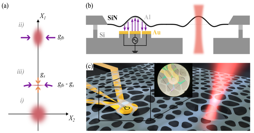
With both the feedback and the parametric modulation turned on, the phase space vector—whose components are represented by a sum of a coherent amplitude and a fluctuating component —fluctuates around the equilibrium position , where and is the squeezing rate. The equations for the residual fluctuations of the two quadratures in the Fourier domain read [briant2003]:
| (3) | ||||
where , with the feedback force expressed as , and the thermal force . From Eq. (3) it follows that the two quadratures have different mechanical susceptibilities. The amplitude quadrature , which is in-phase with the parametric modulation, experiences an increased damping rate. Contrarily, as the squeezing increases, the damping of the phase quadrature is reduced. The system reaches the instability threshold when , thereby limiting the maximum squeezing of to , unless the feedback is turned on.
The thermal force quadratures are uncorrelated and the double-sided power spectral density (PSD) reads , with . For the system at equilibrium with the thermal bath, the variances for the two quadratures are:
| (4) |
where .
As such, the protocol allows to get a displaced squeezed state from an initial thermal state. Thanks to the tracking of the mechanical resonance, it is possible to squeeze the amplitude fluctuations below the standard 3 dB limit.
III Experimental Results
In this work, we employ highly-stressed soft-clamped membrane resonators patterned with a phononic crystal. The resonators are operated at room temperature and, in order to minimize the effect of gas damping, at a pressure of . We devise two alternative configurations to drive the membranes parametrically. In the first configuration, we use a membrane hosting a single defect in the center. The membrane is glued on the four sides of the silicon frame to a ring piezoelectric actuator (Piezomechanik, HPCh 150/15-8/3). When a voltage is applied to the actuator, its vertical expansion (contraction) is accompanied by a contraction (expansion) in the horizontal plane. As a result, the membrane experiences a modulation of the stress, and therefore of the resonance frequency, via the shear force applied to the frame, resulting in parametric driving.
The second assembly we explore is illustrated in Fig. 1(b). The membrane hosts a phononic dimer, which gives rise to a symmetric and an anti-symmetric mode whose envelopes span both defects [Catalini2020]. One of the two defects is metallized with a -thick aluminum pad, with a diameter of [Seis2022]. The membrane is then bonded to a silicon chip with a printed circuit consisting of a circular signal electrode surrounded by a grounding rim. The metallized defect forms a capacitor with the underlying electrodes. A voltage applied to the circuit creates a modulation of the elastic constant:
| (5) |
where is the total capacitance and is the equilibrium position of the membrane.
The mechanical motion is detected using a Mach-Zender interferometer operating at a wavelength of [Catalini2020]. The interference signal, measured by a balanced photodetector, is demodulated by a lock-in amplifier (HF2LI, Zurich Instruments) at the mechanical resonance frequency. The lock-in amplifier also provides the signals to drive the mechanical resonance and to apply the parametric modulation.
In order to follow the protocol described in the previous section, the membrane is first driven at resonance. The demodulated signal has a phase offset from the resonant force given by the overall delay caused by the electronics. The resonant force phase is then optimized so that the demodulated quadratures correspond to the phase () and amplitude () quadratures. A PLL within the lock-in amplifier provides the feedback needed to stabilize the phase quadrature by adjusting the driving frequency. The latter is frequency-doubled and the resulting signal is sent to the actuator to apply the parametric drive.
Parametric drive with a piezo
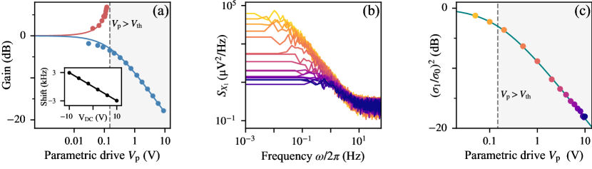
We first study the response of the resonator to the drive scheme shown in Fig. 1(a). The resonator design uses a so called Dahlia-class defect [Rossi_2018] centered in a phononic crystal structure approximately in size, etched into a membrane of stoichiometric LPCVD with a stress of 1.25 GPa. The resonator has a frequency and a quality factor . To certify the quality of the assembly, we first measure the tuning of the resonance frequency with the DC voltage applied to the ring piezo actuator. The shift is linear, with a slope that is typically (inset of Fig. 2(a)).
After turning on the resonant drive and the PLL for the stabilization scheme, we systematically increase the strength of the parametric modulation (i.e. the peak voltage of the signal applied to the piezo actuator) while recording the quadrature. The phase of the parametric drive is chosen to get either deamplification () or amplification () of the amplitude of . The resulting amplitude gain curves, with the gain defined as , are plotted in Fig. 2(a). When is amplified, the feedback (acting only on ) does not provide stabilization and the quadrature can reach the parametric threshold, which occurs when , where is the threshold voltage. On the contrary, when the parametric phase is set such that is the quadrature undergoing squeezing, the threshold can be overcome and a maximum quadrature amplitude reduction of is observed at . Fitting the measured curves results in an estimated .
We verify the performance of the protocol by directly measuring the squeezing of the thermal fluctuations around its steady-state value , as quantified by the variance . We extract from the PSD , at increasingly larger parametric drive voltage (Fig. 2(b)). Each resonance peak is then fitted with a Lorentzian function while discarding the data that lie in the vicinity of 0 Hz. This corresponds to disregarding the coherent amplitude (and additional low-frequency noise) and evaluating the variance of the fluctuations only. The resulting fit parameters are used to calculate the peak area and hence . The variance as a function of is shown in Fig. 2(c). Fitting the model in Eq. (4) returns .
Despite the strong squeezing which can be achieved through the piezo actuation, reaching even larger values is experimentally challenging. Applying larger is not a viable option, due to increased noise levels of the detected mechanical motion, likely attributable to heating of the actuator. Nonetheless, on few assemblies we observed an increase in the squeezing performance—corresponding to a four-fold drop in —when performing the measurement at specific piezo offset voltage . We attribute this enhancement to the presence of an in-plane mode with angular frequency (see Supplementary Information).
Capacitive parametric drive
Next, we analyze the performance of the capacitor-based design. For this, we use a Lotus-class dimer membrane [Planz23], with a thickness of . The dimer symmetric mode has a resonance frequency , with . We first characterize the frequency shift as a function of an applied DC voltage. The capacitor has a nonlinear spring-softening effect (Eq. 5), leading to a change of frequency as shown in the inset of Fig. 3, where is the equilibrium position of the membrane at a given bias voltage .
In order to generate squeezing, we apply a bias voltage . The application of non-zero is required to reach a low threshold value, since [Bothner2020]. Experimentally, we set the bias voltage to . Additionally, we observe that applying a bias voltage increases the quality factor to a value , at the chosen bias voltage.
The variance of at different parametric drive amplitudes (Fig. 3) is obtained following the same steps described in the previous paragraph. Despite the considerably lower -factor compared to the resonator used to study the piezo-actuated drive, the fitted threshold voltage is almost one order of magnitude less, with a value . This results in a maximum observed squeezing of the variance .
Here we remark that the observed value is currently limited by experimental factors, such as low signal-to-noise ratio, heating due to leakage currents in the electrodes, and low mechanical quality factor. Simple improvements to the interferometer sensitivity and to the device fabrication and assembly are predicted to yield significantly larger squeezing.

IV Outlook on quantum squeezing
To assess the experimental feasibility of reaching—and observing—quantum squeezing, we consider a resonant, high finesse optical cavity operating in the bad cavity regime, characterized by a linewidth . Monitoring the output of a resonantly-driven cavity allows measuring mechanical displacements characterized by a rate , where is the optomechanical coupling strength [Aspelmeyer2014], is the cavity intensity decay rate, and is the detection efficiency. The quantum noise of the probe has two detrimental effects on the performance. Its amplitude fluctuations lead to the quantum back action force with a (double sided) power spectral density given by where . The detected signal, referred to the mechanics, is . The quantum uncertainty in the phase of the probe results in an imprecision noise floor in the detection (), not correlated with the mechanics, which the feedback loop attempts to cancel by actuating the mechanical motion (see Supplementary Information). This results in a force on the phase quadrature in the Fourier domain:
| (6) |
where the quadrature of the detected noise signal is defined with the same convention as in Eq. (2).
Adding the backaction of the feedback and of the optical readout in Eq. (3), the variances of the two quadratures read:
| (7) | ||||
where , and is the average occupancy of the thermal bath.
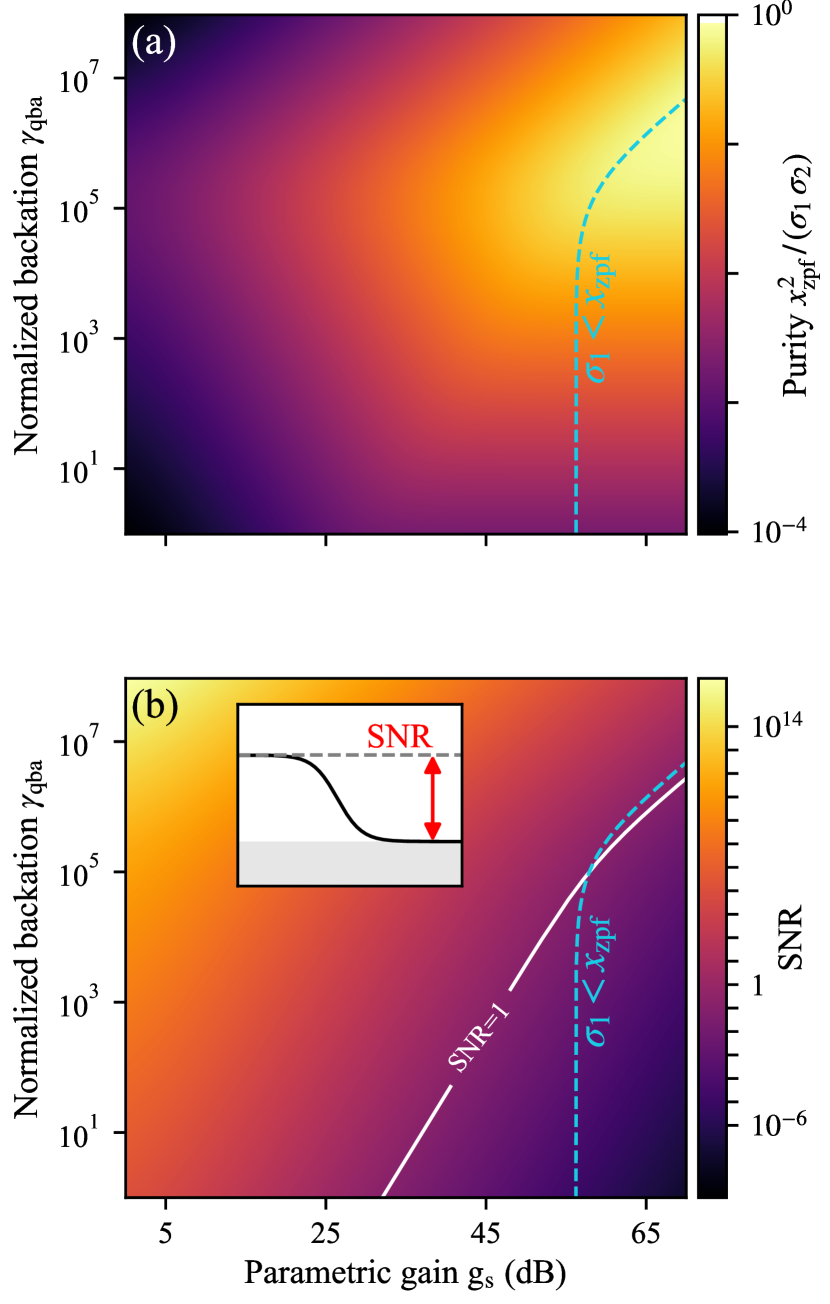
Through Eq. (7), we can estimate the expected purity of the state as a function of the quantum back action and the parametric gain (Fig. 4(a)) for realistic device parameters [Rossi_2018]. For each value of and , the feedback gain is tuned to minimize . The purity approaches in the limit of strong squeezing and fast measurement rate.
The expected detection signal-to-noise ratio (SNR) for the amplitude quadrature is reported in Fig. 4(b). In the limit of strong measurement rate, where the mechanical motion is dominated by the quantum back action, it is possible to squeeze the amplitude quadrature below and detect it with a unity signal-to-noise ratio (SNR) above the imprecision noise.
V Conclusions
By applying active stabilization of the anti-squeezed quadrature, we have shown that both piezo- and capacitively-actuated parametric driving can be used to squeeze the mechanical motion far beyond the limit, reaching and , respectively. Improvements of the device design in the case of piezo actuation are not expected to vastly improve the maximum parametric gain. In contrast, we envision that in the case of capacitive drive, realistic improvements—in terms of larger mechanical quality factor, smaller membrane-electrode separation, and reduced leakage current within the circuit—will result in much larger attainable squeezing, with a scaling of for . Under such modifications, the device will remain compatible with force sensing applications [Halg2021].
We also provide a theoretical model to predict the behaviour of the system in the quantum regime and to discuss the feasibility of squeezing below the zero-point motion. At a moderate bath temperature of , quantum squeezing requires thermomechanical squeezing by more than . We find this can be reached with conservative device parameters (, , and ) with voltages below the threshold for (e.g., pull-in) instability.
VI Acknowledgements
We thank Emil Zeuthen and Jan Košata for fruitful discussions. This work was supported by the European Research Council project PHOQS (Grant No. 101002179), the Novo Nordisk Foundation (Grant No. NNF20OC0061866), as well as the Independent Research Fund Denmark (Grant No. 1026-00345B). L. S. acknowledges financial support from the European Union’s Horizon 2020 research and innovation programme under the Marie Skłodowska-Curie grant agreement No 101063285.
References
- Eichler [2022] A. Eichler, Mater. Quantum. Technol. 2, 043001 (2022).
- Gerberding et al. [2015] O. Gerberding, F. G. Cervantes, J. Melcher, J. R. Pratt, and J. M. Taylor, Metrologia 52, 654 (2015).
- Chaste et al. [2012] J. Chaste, A. Eichler, J. Moser, G. Ceballos, R. Rurali, and A. Bachtold, Nature Nanotech 7, 301 (2012).
- Bagci et al. [2014] T. Bagci, A. Simonsen, S. Schmid, L. G. Villanueva, E. Zeuthen, J. Appel, J. M. Taylor, A. Sorensen, K. Usami, A. Schliesser, and E. S. Polzik, Nature 507, 81 (2014).
- Simonsen et al. [2019] A. Simonsen, S. A. Saarinen, J. D. Sanchez, J. H. Ardenkjær-Larsen, A. Schliesser, and E. S. Polzik, Opt. Express 27, 18561 (2019).
- Braginsky and Khalili [1992] V. B. Braginsky and F. Y. Khalili, Quantum Measurement, edited by K. S. Thorne (Cambridge University Press, 1992).
- Aspelmeyer et al. [2014] M. Aspelmeyer, T. J. Kippenberg, and F. Marquardt, Rev. Mod. Phys. 86, 1391 (2014).
- Mason et al. [2019] D. Mason, J. Chen, M. Rossi, Y. Tsaturyan, and A. Schliesser, Nat. Phys. 15, 745 (2019).
- Yu et al. [2020] H. Yu, L. McCuller, M. Tse, N. Kijbunchoo, L. Barsotti, and N. Mavalvala, Nature 583, 43 (2020).
- Rugar and Grütter [1991] D. Rugar and P. Grütter, Phys. Rev. Lett. 67, 699 (1991).
- Burd et al. [2019] S. C. Burd, R. Srinivas, J. J. Bollinger, A. C. Wilson, D. J. Wineland, D. Leibfried, D. H. Slichter, and D. T. C. Allcock, Science 364, 1163 (2019).
- Wollman et al. [2015] E. E. Wollman, C. U. Lei, A. J. Weinstein, J. Suh, A. Kronwald, F. Marquardt, A. A. Clerk, and K. C. Schwab, Science 349, 952 (2015).
- Pirkkalainen et al. [2015] J.-M. Pirkkalainen, E. Damskägg, M. Brandt, F. Massel, and M. A. Sillanpää, Phys. Rev. Lett. 115, 243601 (2015).
- Lecocq et al. [2015] F. Lecocq, J. B. Clark, R. W. Simmonds, J. Aumentado, and J. D. Teufel, Phys. Rev. X 5, 041037 (2015).
- Seis et al. [2022] Y. Seis, T. Capelle, E. Langman, S. Saarinen, E. Planz, and A. Schliesser, Nat Commun 13, 1507 (2022).
- Tsaturyan et al. [2017] Y. Tsaturyan, A. Barg, E. S. Polzik, and A. Schliesser, Nature Nanotech 12, 776 (2017).
- Hälg et al. [2021] D. Hälg, T. Gisler, Y. Tsaturyan, L. Catalini, U. Grob, M.-D. Krass, M. Héritier, H. Mattiat, A.-K. Thamm, R. Schirhagl, E. C. Langman, A. Schliesser, C. L. Degen, and A. Eichler, Phys. Rev. Applied 15, L021001 (2021).
- Rossi et al. [2018] M. Rossi, D. Mason, J. Chen, Y. Tsaturyan, and A. Schliesser, Nature 563, 53 (2018).
- Huang et al. [2024] G. Huang, A. Beccari, N. J. Engelsen, and T. J. Kippenberg, Nature 626, 512 (2024).
- Kolkowitz et al. [2012] S. Kolkowitz, A. C. B. Jayich, Q. P. Unterreithmeier, S. D. Bennett, P. Rabl, J. G. E. Harris, and M. D. Lukin, Science 335, 1600 (2012).
- Košata et al. [2020] J. Košata, O. Zilberberg, C. L. Degen, R. Chitra, and A. Eichler, Phys. Rev. Applied 14, 014042 (2020).
- Szorkovszky et al. [2013] A. Szorkovszky, G. A. Brawley, A. C. Doherty, and W. P. Bowen, Phys. Rev. Lett. 110, 184301 (2013).
- Vinante and Falferi [2013] A. Vinante and P. Falferi, Phys. Rev. Lett. 111, 207203 (2013).
- Pontin et al. [2014] A. Pontin, M. Bonaldi, A. Borrielli, F. Cataliotti, F. Marino, G. Prodi, E. Serra, and F. Marin, Phys. Rev. Lett. 112, 023601 (2014).
- Poot et al. [2015] M. Poot, K. Y. Fong, and H. X. Tang, New J. Phys. 17, 043056 (2015).
- Briant et al. [2003] T. Briant, P. Cohadon, M. Pinard, and A. Heidmann, Eut. Phys. J. D 22, 131 (2003).
- Catalini et al. [2020] L. Catalini, Y. Tsaturyan, and A. Schliesser, Phys. Rev. Applied 14, 014041 (2020).
- Planz et al. [2023] E. Planz, X. Xi, T. Capelle, E. C. Langman, and A. Schliesser, Opt. Express 31, 41773 (2023).
- Bothner et al. [2020] D. Bothner, S. Yanai, A. Iniguez-Rabago, M. Yuan, Y. M. Blanter, and G. A. Steele, Nat Commun 11, 1589 (2020).