Origin of magnetic switching cascades in tetrahedral CoFe nanostructures
Abstract
We present a comprehensive study of small-scale three-dimensional (3D) tetrahedral CoFe nanostructure arrays prepared by focused electron beam-induced deposition (FEBID) and placed in two distinct orientations with respect to the direction of an external magnetic field. Using ultra-sensitive micro-Hall magnetometry we obtain angular-dependent magnetic stray field hysteresis loops that show characteristic cascading magnetic switching close to zero magnetic field. By employing micromagnetic simulations we could reproduce the hysteresis loops and identify characteristic field dependent magnetic configurations including a vortex-type groundstate. From this we derive a coarse-graining macrospin model and show that the complex switching behavior can be explained by the reorientation dynamics of non-interacting uniaxial anisotropic magnetic grains modeled as a superposition of Stoner-Wohlfarth particles.
Three-dimensional (3D) magnetic nanostructures have become the subject of intense research both in fabrication of ever more complex structures and in applying sophisticated measuring techniques of both, large arrays or individual structures [1, 2, 3, 4]. Lifting the 2D confinement of magnetic structures makes available additional degrees of freedom and leads to new fundamental effects such as topological spin textures [5] or exotic dynamics [6] as well as the possibility for new applications, e.g. in high-density data storage [7]. The recent advancements in fabrication methods of 3D nanomagnets as e.g. in electrochemical deposition, two-photon lithography or 3D nanoprinting enable tailored structures with intriguing properties and create geometry- and curvature-induced effective interactions, see, e.g., [1, 8] and references therein. As building blocks of larger 3D architectures a wealth of different structures have been demonstrated, among them complex 3D tetrapod arrays [9, 7], arrays of multi-axial nano-cubes and nano-trees [10, 11], simple devices such as a nanomagnetic conduits [12] or, recently, curved structures like spirals or twisted ribbons [2, 8, 4]. One notable 3D printing method with high spatial resolution is focused electron beam-induced deposition (FEBID) which allows for the fabrication of high-purity magnetic deposits with tunable growth characteristics, see e.g. [13, 14, 15] for recent reviews. Conveniently, FEBID-grown magnetic nanostructures can be directly written on top of a micro-Hall sensor for local magnetic stray field measurements [16, 17, 18, 10]. This versatile, ultra-sensitive method allows to investigate the switching characteristic of both large arrays and individual nano-scale magnetic structures [19, 20, 21, 18, 22].
In this Letter we present new insights into the magnetization switching dynamics of FEBID-grown small-scale arrays of 3D CoFe tetrahedral nanostructures placed in what we term as ’plus’ and ’cross’ configurations on top of a micro-Hall magnetometer. The structures differ in their relative orientation with respect to each other and the external magnetic field, see Fig. 1. We obtain angular-dependent magnetic stray field hysteresis loops that exhibit a striking cascade switching characteristics upon crossing zero external magnetic field. We show that on the basis of micromagnetic simulations a coarse-graining macrospin model, combining low-field and high-field magnetization states, can be derived that explains these characteristic features accurately by the reorientation dynamics of non-interacting magnetic grains with uniaxial anisotropy.
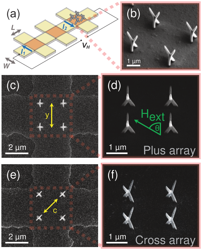
The 3D magnetic nanostructure arrays were directly written onto the active area of a m2 GaAs/AlGaAs micro-Hall sensor by FEBID and consist of metallic bcc Co3Fe. The elementary units are identical tetrahedral nanostructures placed in two small-scale lattice geometries as arrays in ’plus’ and ’cross’ arrangements shown in Figure 1(b)-(f) as scanning electron microscope (SEM) images. One tetrapod’s four pillars are nm in length and nm in diameter each. The perpendicular, -component of the magnetic stray field emanating from the 3D nanostructures averaged over the active area of the Hall cross, , is determined by measuring the Hall voltage generated in the high-mobility two-dimensional electron gas at the interface of a GaAs/AlGaAs heterostructure. An in situ cancellation of the large linear background Hall signal was conducted by a differential measurement of an empty reference cross in a so-called gradiometry setup, see Fig. 1(a), such that , where and are the applied current and the carrier density, respectively. The micro-Hall magnetometer was placed inside a cryogenic system and magnetic field loops have been measured at K with varying field angles with respect to the sensor plane, where the reference angle ° indicates an applied field perpendicular to the plane, cf. Fig. 1(d).
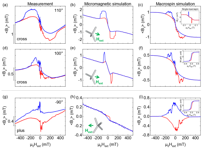
Figures 2(a),(d),(g) exemplarily show the experimental stray field curves at angles of and for the ’cross’, and for the ’plus’ array. Hysteresis loops for other angles are given in the Supplemental Information (SI) [23]. While the hysteresis loops of the magnetization show no unusual features besides the expected constriction at small fields, see inset in Fig. 2(f), for both structures we observe a peculiar overall shape in the magnetic stray field characteristic for the particular field angle. In addition, upon increasing the external field from negative saturation the curves initially are very smooth until T. Upon further increasing the field and thus crossing zero, a series of pronounced spikes appear, see Fig. 2(a,d,g). The same behavior is found for the down cycle starting from positive saturation producing a hysteresis loop, which is nearly perfectly point symmetric in all details with respect to the origin. In order to understand the general shape and the particular spikes we have performed micromagnetic simulations taking into account previous results from microstructure analysis [10]. On that basis we derive a coarse-graining macrospin model that not only reproduces the observed features but also yields the physical explanation.
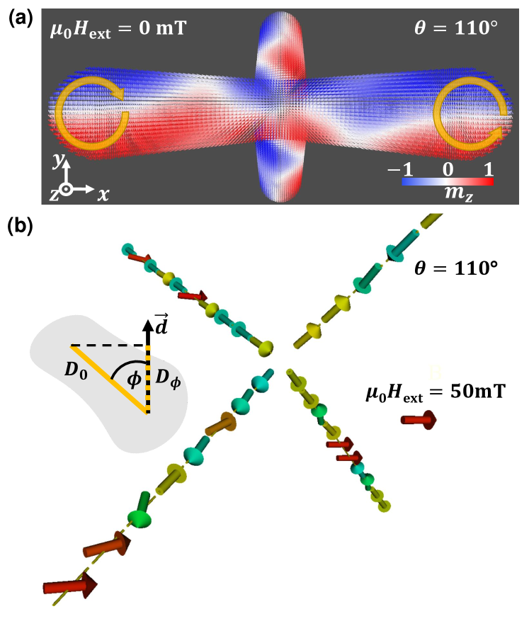
Results of electron diffraction analysis indicate that the microstructure of each pillar is nano-granular and consists of randomly oriented bcc-structured Co-rich CoFe grains with sizes of about nm [10]. Assuming a random orientation of the grains we expect magneto-crystalline anisotropy effects canceling out due to averaging. Furthermore, we find an exponentially decreasing oxidation of the material from the surface of the pillars towards the inside which in turn leads to a decreasing saturation magnetization from inside towards the surface of the pillars. Here, we use a simplified micromagnetic model in which the saturation magnetization is suitably chosen in order to obtain a satisfying agreement with the experiment. We performed simulations using the mumax3 software[24] and the following parameters: saturation magnetization MA/m, exchange stiffness pJ/m, Gilbert damping . Comparing the micromagnetic results shown in Fig. 2(b,e) with the measurements, Fig. 2(a,d), we find a reasonably good qualitative agreement with the overall shape of the hysteresis loop, namely the broad negative peak for positive fields on the up cycle and a broad positive peak for negative fields on the down cycle. Note, that the results of Fig. 2(h) significantly deviate from the experimental results which we will explain below. In Fig. 3(a) we show a snapshot of the magnetic configuration of a ’cross’ array nanostructure at field angle ° and mT. For fields at and close to zero, the magnetic configuration of each pillar collapses into cylindrical vortex states. Taking into account the length/diameter ratio of the pillars and negligible dipole-dipole interaction between the grains, vortex-like magnetization states are energetically favorable which is consistent with our micromagnetic results. At higher fields the magnetic configuration changes to a unaxial magnetization along the pillar axes with different “in-out” directions, and a further alignment of the magnetization with the external field occurs when approaching saturation.
Starting from the uniaxial magnetic configurations at high fields we first derive the simplest possible macrospin model. Here, each pillar is modeled by just one macrospin with magnetic moment placed in the center position of each pillar and with uniaxial anisotropy of strength directed along the pillar axes. The four macrospins of each tetrapod are non-interacting, i.e. only their relative orientation to the external field and placement with respect to the sensor plane is relevant for their stray field contribution. The stray fields are calculated according to
| (1) |
as a superposition of the individual stray fields of the macrospins averaged over the active area of the micro-Hall sensor. A macrospin’s dynamics can be solely described within the framework of the Stoner-Wohlfarth model [25]. We have calculated the stray field component by means of spin dynamics simulations [10] for all experimentally probed directions of the external magnetic field. According to the Stoner-Wohlfarth model, a macrospin has a coercive field of , where is the saturation magnetization. By adjusting and in the simulations we can scale our hysteresis curves to find best possible correspondence with the experiment. In the inset of Fig. 2(c) we show results for °. Even though this is a crudely oversimplified model it reflects the overall shape found in the experiment as well as in the micromagnetic simulations, namely a negative peak at on the up cycle and and a positive peak at on the down cycle.
We now refine our macrospin model so that it also matches the low-field vortex-like magnetic configurations of the pillars where the magnetization of each voxel is oriented along their curved surfaces. Topologically, this magnetic configuration is equivalent to the one where the magnetization directions of all voxels point radially outward since the range of orientation angles for a radial and a chiral spin orientation is identical, except in the vortex core. From this we can derive an effective coarse-graining macrospin model in the following way. We now assume that each grain within a pillar is fully characterized by its total magnetic moment and uniaxial anisotropy with strength . Since the grains are randomly oriented, their anisotropy axes are randomly oriented as well. This is equivalent to the situation where all grain anisotropies point along one direction but have different effective anisotropy strengths according to the projection onto , see inset of Fig. 3(b). If is the polar angle of a grain’s anisotropy axis with respect to , then is the effective anisotropy strength. For randomly oriented grains is evenly random distributed in the interval . However, is not evenly distributed in the interval but peaked at small angles. Thus, there is a bias for larger anisotropies in the direction of the pillar axes. However, in our model we want to realize the opposite effect, i.e. the preferred magnetization direction is pointing radially outward, i.e. perpendicular to the pillar axis. Therefore, we use the inverted distribution given by . We have chosen each pillar to consist of 50 magnetic grains. In the Stoner-Wohlfarth model each according macrospin has a coercive field of and thus, becomes a switching field distribution. In Fig. 2(c,f,i) we show results for our coarse-graining model at the given angles for the ’cross’ and ’plus’ structures using macrospins. The qualitative agreement of the macrospin simulations with the experimental and micromagnetic results is striking, in particular regarding the observed steps and spikes. The overall shape of the curves agrees very well with the micromagnetic simulations for . Note that the macrospin model curves are strictly point-symmetric with respect to the origin which is a result of assuming non-interacting Stoner-Wohlfarth particles. To a large extent our experimental curves show point symmetry as well which corroborates our model considerations. The good agreement of the experimental and macrospin results seems surprising and can be explained as follows. Starting from positive saturation, the macrospins point in the direction of the external field. Upon lowering the field until T the macrospins continuously rotate and relax towards their ground state, i.e. an alignment with their local anisotropy axes. However, after crossing T and depending on the angle of the anisotropy axes with respect to the external field, the macrospins abruptly change their orientation at fields [26], see Fig. 3(b), leading to a switching cascade and hence the observed spikes and steps in the stray field measurements shown in Fig. 2.
Note that the spikes around T do not appear in our micromagnetic simulations. This is due to methodological reasons as we are required to use small cell sizes of edge length 5 nm for the finite difference discretization in order to maintain the necessary accuracy. At around T the pillars are in cylindrical vortex states, thus the magnetization is gradually changing over each cell which has two effects: (i) The total magnetization of the structure is rather small due to canceling effects leading to a small total stray field. (ii) Small changes in only lead to small gradual changes of the magnetization per cell and thus cause only small stray field changes, i.e. no spikes. In contrast to this, each macrospin represents a large magnetic moment that switches at resulting in large stray field changes and spikes, even at fields around T.
As a prediction of our coarse-graining model one should find a characteristic -dependence of the total stray field amplitude for each hysteresis loop. For ° the external field is exactly parallel to the Hall cross, i.e. points along the -direction. At saturation and on lowering the field the grains’ magnetization is more or less pointing in the -direction as well. Thus, the -component of the grains’ magnetization is close to zero and their stray field contribution to is very small for most fields, except for the fields at which the grains flip. The hysteresis curves at and around ° therefore show the most noticeable “fingerprint” of the grain switching cascade, however resulting in the smallest total stray field amplitude . On decreasing , the -component of the grains’ magnetization increases and thus increases as well. As a consequence, the relative stray field contribution of the grain switching cascade to becomes smaller, leading to less pronounced spikes and steps with the least contribution at °. Indeed, we find this behaviour in the experimental and micromagnetic data, see the SI for details[23].
For a further proof of our model we have performed experiments with field sweeps where T is crossed and field sweeps where T is not crossed. In the latter case one expects fewer spikes and steps since the coercive fields can not be reached and thus grain flips do not occur. Indeed, we observe that avoiding zero-field crossing while sweeping the field leads to fewer and smaller spikes and steps, see SI[23].
In conclusion, we have successfully modeled the magnetization reversal of FEBID-prepared small-scale arrays of tetrahedral CoFe nanostructures placed in ’plus’ and ’cross’ configurations with respect to the direction of an external magnetic field. We have shown that the physics of the characteristic features of the measured stray field hysteresis loops can be understood by considering non-interacting magnetic grains, each described by a simple Stoner-Wohlfarth model with anisotropy axis aligned along the pillar directions of the nanostructures. By assuming a distribution of anisotropy strengths due to a random distribution of the grain orientations we obtain a distribution of coercive fields. This leads to magnetic switching cascades of the grains during a field sweep which manifest themselves as steps and spikes in stray field measurements. The coarse-graining macrospin simulations catch the essential switching dynamics of vortex-like magnetization states with rather short computing times of a few minutes per angle on a laptop as compared to several hours for GPU-accelerated micromagnetic simulations. This may be advantageous when calculating larger and more complex structures.
Acknowledgements
The authors thank Prof. Dr. Jürgen Weis from the Max-Planck Institute for Solid State Research (Stuttgart, Germany) for providing the GaAs/AlGaAs high-mobility wafer material. M.L. acknowledges financial support through the FOKUS program by the Goethe Research Academy for Early Career Researchers (GRADE). The contribution of M.H. was supported by DFG funding (project HU 752/16-1; Frankfurt Center for Electron Microscopy (FCEM)).
Author Declarations
The authors have no conflicts to disclose.
Data availability
The data that support the findings of this study are available from the corresponding author upon reasonable request.
References
- Fernández-Pacheco et al. [2017] A. Fernández-Pacheco, R. Streubel, O. Fruchart, R. Hertel, P. Fischer, and R. P. Cowburn, “Three-dimensional nanomagnetism,” Nature Communications 8 (2017), ARTN 15756 10.1038/ncomms15756.
- Streubel et al. [2016] R. Streubel, P. Fischer, F. Kronast, V. P. Kravchuk, D. D. Sheka, Y. Gaididei, O. G. Schmidt, and D. Makarov, “Magnetism in curved geometries,” Journal of Physics D: Applied Physics 49, 363001 (2016).
- Donnelly et al. [2017] C. Donnelly, M. Guizar-Sicairos, V. Scagnoli, S. Gliga, M. Holler, J. Raabe, and L. J. Heyderman, “Three-dimensional magnetization structures revealed with x-ray vector nanotomography,” Nature 547, 328–331 (2017).
- Sheka et al. [2022] D. D. Sheka, O. V. Pylypovskyi, O. M. Volkov, K. V. Yershov, V. P. Kravchuk, and D. Makarov, “Fundamentals of curvilinear ferromagnetism: Statics and dynamics of geometrically curved wires and narrow ribbons,” Small 18, 2105219 (2022), https://onlinelibrary.wiley.com/doi/pdf/10.1002/smll.202105219 .
- Donnelly et al. [2022] C. Donnelly, A. Hierro-Rodríguez, C. Abert, K. Witte, L. Skoric, D. Sanz-Hernández, S. Finizio, F. Meng, S. McVitie, J. Raabe, D. Suess, R. Cowburn, and A. Fernández-Pacheco, “Complex free-space magnetic field textures induced by three-dimensional magnetic nanostructures,” Nature Nanotechnology 17, 136–142 (2022).
- Finizio et al. [2022] S. Finizio, C. Donnelly, S. Mayr, A. Hrabec, and J. Raabe, “Three-dimensional vortex gyration dynamics unraveled by time-resolved soft x-ray laminography with freely selectable excitation frequencies,” Nano Letters 22, 1971–1977 (2022).
- Koraltan et al. [2021] S. Koraltan, F. Slanovc, F. Bruckner, C. Nisoli, A. V. Chumak, O. V. Dobrovolskiy, C. Abert, and D. Suess, “Tension-free dirac strings and steered magnetic charges in 3d artificial spin ice,” npj Computational Materials 7, 125 (2021).
- Streubel, Tsymbal, and Fischer [2021] R. Streubel, E. Y. Tsymbal, and P. Fischer, “Magnetism in curved geometries,” Journal of Applied Physics 129, 210902 (2021), https://pubs.aip.org/aip/jap/article-pdf/doi/10.1063/5.0054025/15262015/210902_1_online.pdf .
- Williams et al. [2018] G. Williams, M. Hunt, B. Boehm, A. May, M. Taverne, D. Ho, S. Giblin, D. Read, J. Rarity, R. Allenspach, et al., “Two-photon lithography for 3d magnetic nanostructure fabrication,” Nano Research 11, 845–854 (2018).
- Keller et al. [2018] L. Keller, M. K. Al Mamoori, J. Pieper, C. Gspan, I. Stockem, C. Schröder, S. Barth, R. Winkler, H. Plank, M. Pohlit, et al., “Direct-write of free-form building blocks for artificial magnetic 3d lattices,” Scientific reports 8, 1–13 (2018).
- Al Mamoori et al. [2018] M. K. Al Mamoori, L. Keller, J. Pieper, S. Barth, R. Winkler, H. Plank, J. Müller, and M. Huth, “Magnetic characterization of direct-write free-form building blocks for artificial magnetic 3d lattices,” Materials 11, 289 (2018).
- Sanz-Hernandez et al. [2017] D. Sanz-Hernandez, R. F. Hamans, J.-W. Liao, A. Welbourne, R. Lavrijsen, and A. Fernández-Pacheco, “Fabrication, detection, and operation of a three-dimensional nanomagnetic conduit,” ACS Nano 11, 11066–11073 (2017).
- Plank et al. [2020] H. Plank, R. Winkler, C. H. Schwalb, J. Hütner, J. D. Fowlkes, P. D. Rack, I. Utke, and M. Huth, “Focused electron beam-based 3d nanoprinting for scanning probe microscopy: A review,” Micromachines 11 (2020), 10.3390/mi11010048.
- Fernández-Pacheco et al. [2020] A. Fernández-Pacheco, L. Skoric, J. M. De Teresa, J. Pablo-Navarro, M. Huth, and O. V. Dobrovolskiy, “Writing 3d nanomagnets using focused electron beams,” Materials 13 (2020), 10.3390/ma13173774.
- Magén, Pablo-Navarro, and De Teresa [2021] C. Magén, J. Pablo-Navarro, and J. M. De Teresa, “Focused-electron-beam engineering of 3d magnetic nanowires,” Nanomaterials 11 (2021), 10.3390/nano11020402.
- Porrati et al. [2015] F. Porrati, M. Pohlit, J. Müller, S. Barth, F. Biegger, C. Gspan, H. Plank, and M. Huth, “Direct writing of cofe alloy nanostructures by focused electron beam induced deposition from a heteronuclear precursor,” Nanotechnology 26, 475701 (2015).
- Pohlit et al. [2015] M. Pohlit, F. Porrati, M. Huth, Y. Ohno, H. Ohno, and J. Müller, “Nanocluster building blocks of artificial square spin ice: Stray-field studies of thermal dynamics,” Journal of Applied Physics 117, 17C746 (2015).
- Pohlit et al. [2016a] M. Pohlit, F. Porrati, M. Huth, Y. Ohno, H. Ohno, and J. Müller, “Magnetic stray-field studies of a single cobalt nanoelement as a component of the building blocks of artificial square spin ice,” Journal of Magnetism and Magnetic Materials 400, 206–212 (2016a).
- Wirth and Molnár [2000] S. Wirth and S. v. Molnár, “Hall cross size scaling and its application to measurements on nanometer-size iron particle arrays,” Applied Physics Letters 76, 3283–3285 (2000), https://pubs.aip.org/aip/apl/article-pdf/76/22/3283/10183526/3283_1_online.pdf .
- Li et al. [2002] Y. Li, P. Xiong, S. von Molnár, S. Wirth, Y. Ohno, and H. Ohno, “Hall magnetometry on a single iron nanoparticle,” Applied Physics Letters 80, 4644–4646 (2002).
- Pohlit et al. [2016b] M. Pohlit, I. Stockem, F. Porrati, M. Huth, C. Schröder, and J. Müller, “Experimental and theoretical investigation of the magnetization dynamics of an artificial square spin ice cluster,” Journal of Applied Physics 120, 142103 (2016b), https://pubs.aip.org/aip/jap/article-pdf/doi/10.1063/1.4961705/13272844/142103_1_online.pdf .
- Al Mamoori et al. [2020] M. Al Mamoori, C. Schröder, L. Keller, M. Huth, and J. Müller, “First-order reversal curves (FORCs) of nano-engineered 3D Co-Fe structures,” AIP Advances 10, 015319 (2020), https://pubs.aip.org/aip/adv/article-pdf/doi/10.1063/1.5129850/13011049/015319_1_online.pdf .
- [23] See Supplemental Material at DOI ….
- Vansteenkiste et al. [2014] A. Vansteenkiste, J. Leliaert, M. Dvornik, M. Helsen, F. Garcia-Sanchez, and B. V. Waeyenberge, “The design and verification of MuMax3,” AIP Advances 4, 107133 (2014).
- Stoner and Wohlfarth [1948] E. C. Stoner and E. Wohlfarth, “A mechanism of magnetic hysteresis in heterogeneous alloys,” Philosophical Transactions of the Royal Society of London. Series A, Mathematical and Physical Sciences 240, 599–642 (1948).
- Tannous and Gieraltowski [2008] C. Tannous and J. Gieraltowski, “The Stoner–Wohlfarth model of ferromagnetism,” European Journal of Physics 29, 475 (2008).