Measurements of the first-flux-penetration field in surface-treated and coated \chNb:
Distinguishing between surface pinning and an interface energy barrier
Abstract
We report measurements of the first-flux-penetration field in surface-treated and coated \chNb samples using muon spin rotation (SR). Using thin \chAg foils as energy moderators for the implanted muon spin-probes, we “profile” the vortex penetration field at sub-surface depths on the order of \qtyrange∼10∼100\micro. In a coated sample [\chNb3Sn(\qty2\micro)/\chNb], we find that is depth-independent with a value of \qty234.5 ±3.5\milli, consistent with \chNb’s metastable superheating field and suggestive of surface energy barrier for flux penetration. Conversely, in a surface-treated sample [\chNb baked in vacuum at \qty120 for \qty48], vortex penetration onsets close to pure \chNb’s lower critical field , but increases with increasing implantation depth, consistent with flux-pinning localized at the surface. The implication of these results for technical applications of superconducting \chNb, such as superconducting radio frequency (SRF) cavities, is discussed.
I Introduction
A key technical application of the elemental type-II superconductor \chNb is its use in superconducting radio frequency (SRF) cavities [1, 2, 3], which are utilized in particle accelerators across the globe. Crucial to their operation is maintaining \chNb in its magnetic-flux-free Meissner state (i.e., to prevent dissipation caused by magnetic vortices), which generally restricts their use to surface magnetic fields up to the element’s lower critical field [4]. Such a limitation ultimately sets a ceiling for a cavity’s maximum accelerating gradient (i.e., the achievable energy gain per unit length), which impacts design considerations for accelerating structures (e.g., size, operating temperature, etc.). Consequently, there is great interest in pushing SRF cavity operation up to \chNb’s so-called superheating field [5, 6], where the Meissner state is preserved in a metastable configuration. Currently, the largest gradients are achieved by so-called low-temperature baking (LTB) surface treatments, wherein a \chNb cavity is baked at temperatures on the order of \qty∼120 either in vacuum [7, 8] or in a low-pressure gas atmosphere [9, 10]. Indeed, the best performing treatments have enabled cavities to achieve surface magnetic fields beyond (with some even approaching ) [5]; however, the underlying mechanism for this enhancement remains unclear.
Consider, as an example, one of the oldest LTB treatments: vacuum annealing \chNb at \qty120 for up to \qty48 [7], Early measurements of this treatment’s effect on \chNb’s Meissner response using low-energy muon spin rotation (LE-SR) [11, 12] showed a sharp discontinuity in the screening profile [13], which led to suggestions that LTB can be used to create an “effective” superconductor-superconductor (SS) bilayer [14]. Of particular interest for SRF applications is the case where a thin “dirty” layer resides atop a “clean” bulk (e.g., as a result of surface-localized inhomogeneous doping), as it offered several avenues for increasing the vortex penetration field via a reduced current density at \chNb’s surface (e.g., following directly from the SS-like structure [14] or as a consequence of deformations found in the Meissner profile itself [15, 16]). While both theories [14] and measurements [13] have been presented that support the interpretation of a surface barrier originating from a “dirty” layer, other measurements [17] and analyses [18] contradict such views. To resolve this discrepancy, additional measurements using alternative approaches would be highly beneficial.
One such possibility is instead using techniques capable of identifying directly. This has been done, for example, using “bulk” muon spin rotation (SR) [19, 20], which provides a local measurement of the magnetic field \qty∼100\micro below \chNb’s surface. Such studies have found for both LTB and coated \chNb [21], the latter yielding [6]. While this provided strong evidence that a surface energy barrier [22] was preventing flux nucleation in SS samples, some ambiguity in interpreting the enhancement from LTB remained. Specifically, subsequent magnetometry measurements on identically prepared samples showed no such enhancement [4], implying an accumulation of near-surface vortices caused by pinning. The discrepancy between SR and magnetometry suggests that any pinning centers must be localized to depths less than \qty∼100\micro below \chNb’s surface.
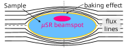
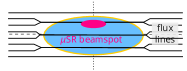
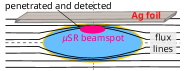
To test these ideas, here we extend the “bulk” SR approach used in related work [23, 6, 21] to provide depth-resolved measurements of in both surface-treated and coated \chNb. Specifically, we make use of thin \chAg foils to moderate the implantation energy of the muon spin probes, providing spatial sensitivity to depths on the order of \qtyrange∼30∼100\micro. In the presence of surface energy barrier [22], is expected to be depth-independent, whereas surface-localized pinning is anticipated to produce larger s deeper below the surface (see Figure 1). Using this approach, we find that is depth-independent and close to \chNb’s for a \chNb sample coated with the A15 superconductor \chNb3Sn [24, 25], consistent with the energy barrier expected for the SS bilayer. Conversely, for \chNb that has been surface-treated by LTB at \qty120, the measured s are comparable to \chNb’s , but increase deeper below the surface, suggesting the presence of localized pinning near the surface that prevents detection by deeper implanted muons.

II Experiment
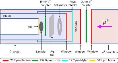
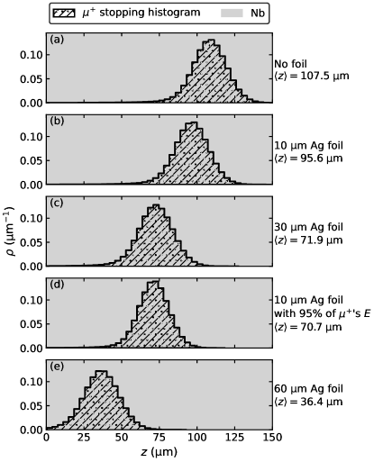
experiments were performed at TRIUMF’s Centre for Molecular and Materials Science (CMMS) facility in Vancouver, Canada. Using the M20C beamline [26], a \qty∼100 spin-polarized \qty∼4.1\mega “surface” beam was extracted, spin-rotated in flight, and delivered to the high-parallel-field (i.e., “HodgePodge”) spectrometer equipped with a horizontal gas-flow cryostat and a low-background (i.e., Knight shift) insert [26]. A sketch of cryostat configuration is given in Figure 2. This setup is similar to that used in related experiments [23, 6, 21], with the external magnetic field parallel to each sample’s surface (see Figure 1) and perpendicular to the implanted spin direction. Notably, the present work also incorporates thin \chAg foils (Goodfellow, \qty99.95 purity, \qtyrange1030\micro thick) as part of the cryostat assembly, acting as energy moderators for the beam. By varying the thickness of the foils, the range of implanted in the \chNb samples can be controlled on the \unit\micro scale. Simulations of the moderating effect were performed using the Stopping and Range of Ions in Matter (SRIM) Monte Carlo code [27], which incorporated all major materials along the beam’s path (e.g., muon counters, moderator foils, etc. — see Figure 2), as well as compound corrections [28] to the stopping powers (where appropriate). Typical stopping profiles for this setup are shown in Figure 3, showing mean stopping ranges between \qtyrange∼36∼108\micro for a \chNb target. Note that similar simulations for \chNb_3Sn()/\chNb samples (not shown) yielded virtually identical results. In cases where a \qty60\micro \chAg foil was used, a small fraction (\qty∼2) of the implanted probes stop in the inner counter, located immediately upstream of the sample (see Figure 2).
In SR, the implanted spin probes (spin , gyromagnetic ratio , lifetime ) are sensitive to the local magnetic field at their stopping sites, with the temporal evolution of the ensemble’s spin-polarization monitored via the anisotropic property of radioactive -decay. Specifically, each decay positron’s emission direction is statistically correlated with the spin direction at the moment of decay, providing an easy means of tracking spin-reorientation. Specifically, in a two-detector setup like that used here (see Figure 2), the recorded histogram of decay events takes the form:
| (1) |
where denotes each detector, is the time (in \unit\micro) after implantation, and denote the rate of “good” and “background” decay events, is the muon spin-polarization, and is a proportionality constant ( here). The most important part of Equation 1 is and it may be obtained directly by taking the asymmetry of two counters:
| (2) |
where accounts for imperfections in the detector pair (e.g., different efficiencies, effective solid angles, etc.). Important for this work is the temporal evolution of , which contains all information about the local magnetic environment below the sample’s surface (i.e., at the stopping site). Fortunately, differs in each of \chNb’s superconducting states, allowing us to quantify their volume fraction for our set of measurement conditions.
For the simplest case of \chNb’s normal state, where magnetic flux penetrates the sample’s surface freely, the SR signal follows that of a typical transverse-field measurement [19]:
| (3) |
where is the time after implantation, is the damping rate (from a Gaussian field distribution), is magnetic field at the stopping site (dominated by the external applied field), and is a phase factor. In non-superconducting \chNb, the term [23, 6, 21], causing minimal damping. Conversely, in \chNb’s vortex state, where fluxoids form a periodic arrangement with a broad distribution [29, 30], is much larger and the signal is damped quickly (i.e., within the first \qty∼0.3\micro following implantation). In the opposite limit of \chNb’s Meissner state, where all magnetic flux is expelled from the sample’s interior, the signal follows that of a so-called dynamic zero-field Kubo-Toyabe function [31]:
| (4) |
which is obtained from a static Kubo-Toyabe function [32]:
| (5) |
where the local field is fluctuating (e.g., from stochastic site-to-site “hopping” of [33]) at a rate , typically \qty∼0.7\per\micro for SRF \chNb [23, 34]. Note that both Equations 4 and 5 assume the local field distribution at the stopping site to be Gaussian, in accord with related studies [23, 6, 34, 21].
For the present experiments, the SR signal is, in general, described by a superposition of Equations 3 and 4, which may be written as:
| (6) |
where denotes the volume fraction of the zero-field component, which for superconducting \chNb in an applied field corresponds to its Meissner state, and represents the individual transverse-field components (e.g., normal state, vortex state, etc.), subject to the constraint that . Examples of this type of composite signal are shown in Figure 4.
In order to identify the in each sample, the evolution of in (monotonically increasing) magnetic fields up to \qty∼260\milli was measured at the cryostat’s base temperature () following zero-field cooling. Any depth-dependence was inferred from repeat measurements using different moderator foil thicknesses (and beam energies). Note that, to ensure the accuracy of the applied fields reported for all superconducting states (i.e., due to its geometric enhancement from flux-expulsion), all values were derived from field calibration measurements conducted above (i.e., at for the LTB \chNb and for the SS bilayer), where the SR signal simply follows Equation 3. Specifically, they were corrected using [35]:
| (7) |
where is the (measured) applied field in the normal state and [6, 21] is the demagnetization factor for our samples (see Section II.1).
II.1 Samples
The samples used in this study are identical to those employed in previous SR measurements on the first-flux-penetration field [6, 21]. For completeness, we briefly restate their preparation details below.
Each \chNb sample was cut from high residual-resistivity ratio (RRR) (i.e., ) stock sheets and machined into prolate ellipsoids with a semi-major radius \qty22.9\milli and semi-minor radii \qty9.0\milli for the other axes. After machining, the samples underwent buffered chemical polishing (BCP) to remove the surface’s topmost \qty100\micro of the material (see, e.g., [36]). For one of the samples, a typical LTB “recipe” was followed where, after degassing in vacuum at \qty800 for \qty4, the \chNb ellipsoid was baked in vacuum at \qty120 for \qty48 [7]. For another sample, a \qty2\micro \chNb3Sn surface coating was applied using a vapour diffusion [37, 38] procedure developed at Cornell University [39, 40]. A complementary magnetostatic characterization of the LTB sample can also be found elsewhere [4].
III Results
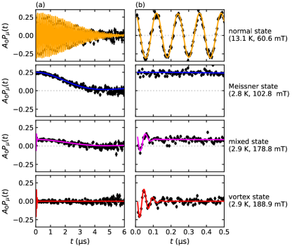
Figure 4 depicts typical time-differential SR data in one of our samples (LTB \chNb [7]), showing the contrast in signals for different material states. In the normal state, where the local field at the stopping sites is dominated by the (transverse) applied magnetic field , coherent spin-precession is observed with minimal damping, consistent with a narrow field distribution. By contrast, in the Meissner state, is completely screened 111The range of implanted greatly exceeds \chNb’s London penetration depth (\qty∼29\nano [17]), leading to the absence of magnetic flux density for depths greater than \qty∼100. and the local field is dominated, in part, by \chNb’s \qty100 abundant \ch^93Nb nuclear spins, resulting in the characteristic (dynamic) “zero-field” signal [31]. At applied fields just above the vortex penetration field , a mixed signal with both zero- and transverse-field components is observed, the latter being strongly damped. As the field is further increased beyond , the sample fully enters a vortex state, where the signal resembles that of the normal state, but the broad field distribution from the vortex lattice causes strong damping of the spin-polarization. Similar behavior is observed at other implantation ranges, as well as in the \chNb3Sn(\qty2\micro)/\chNb sample (not shown). In line with the experiment’s description in Section II, these observations can be quantified through fits to Equation 6, yielding good agreement with the data in all cases (typical reduced-). A subset of the fit results are shown in Figure 4.
To aid in identifying and its depth-dependence, we plot the measured s vs. for each \chNb sample in Figure 5. The resulting “curves” all have a sigmoid-like shape, where for , with decreasing rapidly towards zero once . This behavior is phenomenologically captured by a logistic function:
| (8) |
where is the curve’s height, denotes the “steepness” of the transition, and represents its midpoint. Fits of the measured volume fractions to Equation 8 are shown in Figure 5 as guides to the eye.
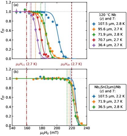
It is clear from Figure 5 that ’s depth-dependence is quite different for LTB and coated \chNb. In the LTB sample, flux-penetration is detected just above \chNb’s , with the onset pushed to higher s for larger ranges. Similarly, the field span of this “transition” (i.e., going from zero- to full-flux-penetration) also increases slightly deeper below the surface. By contrast, in the \chNb3Sn(\qty2\micro)/\chNb, first-flux-penetration onsets close to \chNb’s , with this value and the transition’s width both virtually unaffected by ’s proximity to the sample’s surface. Qualitatively, this disparity between the \chNb treatments indicates that different mechanisms are likely responsible for determining each sample’s .
To quantify these differences explicitly, we use a non-parametric approach to identify for each “curve” in Figure 5. Noting that each has a statistical uncertainty of \qty∼4 (determined from fitting), we define to correspond to the applied field where where (i.e., the very onset of flux-penetration). Due to the finite “sampling” of our measurements, this field is estimated as midpoint between the pair of s on either side of the threshold criteria 222While simple, this approach introduces an additional systematic uncertainty to the assignment of . We estimate this quantity as one-sixth the distance between the field points, such that standard deviations covers the full span of the “uncertain” region with \qty∼100 probability.. These values are marked graphically in Figure 5 by vertical dotted colored lines. Similarly, we take the width of the zero- to full-flux-penetration “transition” to be the field range where . To correct for any influence from the finite span of the stopping profile (see Figure 3), we additionally normalize the s by the width of the implantation distribution. For each of our samples, the dependence of both and on the implanted range is shown in Figure 6. For comparison, measured values for additional surface-treated samples [6, 21] have also been included 333To ensure the self-consistency of our comparison in Figure 6, following the approach described in Section II, we re-analyzed the raw SR data for select samples originally reported in Refs. 6, 21. As anticipated, our updated values are in good agreement with those in the original reports.. Lastly, to facilitate comparison between the measured s, we correct for minor temperature differences and extrapolate our values to \qty0 using the empirical relation [44]:
| (9) |
where is the absolute temperature, is \chNb’s critical temperature [45], and is the value at absolute zero.
IV Discussion
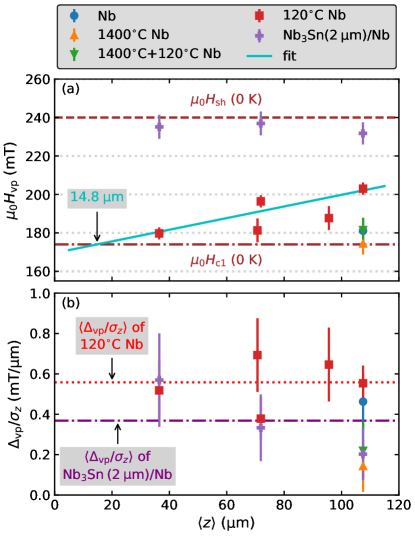
Consistent with our main observations in Figure 5 for the vortex penetration field, Figure 6(a) shows that s in \chNb3Sn(\qty2\micro)/\chNb (extrapolated to \qty0) remain depth-independent with an average value of \qty234.5 ±3.5\milli, in excellent agreement with \chNb’s [5, 6]. That the flux penetration occurs in such close proximity to the superheating field is strong evidence for the presence of an interface barrier at the SS boundary, similar to a Bean-Livingston (BL) surface energy barrier [22], as anticipated by the theoretical framework for superconducting multilayers [14, 46]. Conversely, in LTB \chNb the s are much lower, remaining close to (but slightly above) for all measurements. In this case, however, a modest depth-dependence is observed, with increasing gradually with increasing . That these details coincide is significant, as it sets LTB apart from other surface treatments, where flux-penetration occurs at \chNb’s lower critical field. We note that, though small, the observation of such a depth-dependence is inconsistent with a surface energy barrier being solely responsible for pushing 444A similar argument can be made for the \chNb3Sn(\qty2\micro)/\chNb sample (i.e., that flux pinning — particularly from the thin \chNb_3Sn layer — may contribute to the increased we observe). We point out, however, that the observed lack of depth-dependence in our data, along with the magnitude in which exceeds \chNb’s , suggest that pinning is not the dominant mechanism for elevating the vortex penetration field in the SS bilayer.. An alternative possibility is the presence of pinnning centers localized near LTB \chNb’s surface, which has been suggested previously [21, 4]. In such a case, closely approximates due to the presence of pinning, which diminishes towards the sample’s center, resulting in delayed flux penetration (i.e., the pinning centers act as supplemental flux “blockades,” providing resistance to the free motion of the fluxoids, which would otherwise uniformly distribute throughout the sample) [21]. Independent of the mechanistic details, from our data we identify the length scale over which flux-penetration is retarded. Using a simple linear fit to the measured values, we find that at a mean depth of \qty∼14\micro, characterizing the distance in which it is delayed for our sample geometry. Note that, there is a significant proportion of muons that stop significantly closer to the surface at this average depth. We shall return the implications of this quantity later on.
Further insight into the flux-penetration mechanism for the LTB and SS samples can be gleaned from the (normalized) flux-entry “transition” widths , which are shown in Figure 6(b). The span from first- to full-flux penetration provides a measure for the “haste” in which vortices nucleate through the probe stopping depths where, in the presence of surface pinning, we expect that the Meissner-vortex transition becomes “extended” to a larger range of applied fields (i.e., the presence of pinning centers delays full-flux penetration). Thus, we suggest that serves as a proxy for each treatment’s pinning strength. Indeed, we observe that the values for LTB \chNb are all similar, which also suggests that the pinning strength appears to be depth-independent and exceeds the values of all other surface preparations shown in Figure 6. However, given the relatively large uncertainty in each measurement, drawing firm conclusions about treatment-specific differences is challenging. This is clear from their average values, which turned out to be \qty0.56 ±0.15\milli/\micro (for LTB) and \qty0.37 ±0.18\milli/\micro (for \chNb3Sn(\qty2\micro)/\chNb), respectively. Interestingly, both quantities are comparable to that of \chNb in the absence of any treatment (\qty0.46 ±0.14\milli/\micro), which is larger than both the values obtained for \qty1400 annealing (\qty0.14 ±0.13\milli/\micro), as well as \qty1400 annealing + \qty120 LTB (\qty0.22 ±0.14\milli/\micro). We note that, in line with our expectations for , its value is minimized for the \qty1400 treatment, which is known to release virtually all pinning [21]. Thus, although not as conclusive as the measurements, the large values for LTB insinuate that pinning is strongest for this treatment. With these results in mind, we will explore their implications in the remaining discussion.
First, we consider the SS bilayer \chNb3Sn(\qty2\micro)/\chNb, whose high is favourable for technical applications requiring operation in a flux-free state (e.g., SRF cavities). In fact, direct current (DC) measurements of first-flux-penetration using a Hall probe magnetometer on a \qty1.3\giga single-cell SRF cavity of similar composition are in good agreement with our result [5], with similar values reported for surface coatings other than \chNb3Sn, such as hybrid physical chemical vapour deposition (HPCVD) \chMgB2 [6]. The combination of our work and related studies [6, 21, 5] provides compelling evidence for the use of SS bilayers as an empirical means for increasing , consistent with earlier observations using SR [6, 21]. For further insight into why such a treatment is so effective at enhancing , we must consider the theory of superconducting multilayers (see, e.g., [14]), which we shall briefly outline below.
In bilayer superconductors, by analogy with the BL barrier at the surface of “bulk” superconductors [22], the discontinuity in each material’s (coupled) electromagnetic response at the SS interface is responsible for creating a second (sub-surface) barrier that impedes flux penetration [46]. Specifically, electromagnetic continuity across the SS boundary creates a “coupling” between the layer’s properties, leading to marked deviations from the lone material’s native behavior when the surface layer penetration depth is larger than the substrate. Microscopically, this is predicted to manifest in the heterostructure’s Meissner screening profile with a distinct bipartite form [46], which was recently confirmed experimentally for \chNb_1-xTi_xN(\qtyrange50160\nano)/\chNb samples [48]. A weaker Meissner screening current is observed, which, as a corollary, provides enhanced protection against flux nucleation (see, e.g., [14]). While the we observe is in good agreement with this prediction, the theory also suggests that can be improved further still through optimizing the \chNb3Sn coating’s thickness. This enhancement is achievable by ensuring a flux-free surface layer and enabling superheating in both the surface and substrate layers. Achieving this involves precise adjustments to the thickness of the surface layer and the presence of an interface barrier at the SS boundary for the substrate layer. For an SS structure, the optimum thickness of the surface layer is defined by [14]:
| (10) |
where and denote the magnetic penetration depth and superheating field for the surface ( = s) and substrate ( = sub) layers. Using literature values for these quantities ( [49, 5]; [5, 49]; [17]; and [5, 6]), Equation 10 yields or, equivalently, . Similar predictions have been made for \chNb_1-xTi_xN/\chNb [48]. It would be interesting to test these explicitly, for example, using the experimental formalism employed in this work. Investigating this phenomena in closely related superconductor-insulator-superconductor (SIS) heterostructures would also be fruitful, as they offer similar means of enhancing [14].
As a close to our discussion of the \chNb_3Sn/\chNb bilayer, it is interesting to consider its synthesis. We note that in our sample, as is common for heterostructures prepared by thermal diffusion, the composition of the \chNb_3Sn/\chNb interface deviates appreciably from each layer’s respective “bulk” [25, 50]. Specifically, within the first few hundred nanometers from the heterojunction, a localized \chSn deficiency (enhancement) is present in the \chNb3Sn (\chNb) layers, with the former known to lower \chNb3Sn’s , making the region a poor superconductor [25, 50]. The presence of such inhomogeneities, however, do not meaningfully impact , as indicated by it’s agreement with \chNb’s . Testing the extent in which this remains true, for example, on samples with extended defect regions, would be interesting. Similarly, these nanoscale inhomogeneities at the SS interface could be examined directly using a depth-resolved technique such as LE-SR [12, 11], with the caveat that the \chNb3Sn layer thickness must be compatible with the technique’s spatial sensitivity (i.e., subsurface depths typically \qty< 150\nano). Finally, given the presence of a secondary energy barrier at the SS interface, we suggest that incorporating SS bilayers into SRF cavity structures holds great promise for surpassing the inherent limitations of current \chNb cavity technology (i.e., enabling higher accelerating gradients and enhanced performance in particle accelerators).
We now turn our attention to the \qty120 LTB treatment [7], which is well-known in SRF applications for its ability to alleviate the so-called high-field slope (HFQS) “problem” [2, 51], where a rapid decrease in a cavity’s quality factor () occurs as the peak surface magnetic field exceeds \qty∼100\milli 555Note that, in regards to HFQS mitigation, the most effective LTB treatments generally include an electropolishing (EP) step in place of the BCP used in this work.. True to this fashion, our finding of s in excess of \chNb’s underscores its utility in this domain; however, the treatment’s depth-dependent and relatively large make it unique among the comparison treatments reported here. As mentioned above, surface pinning of the flux-lines provides the most likely explanation for these facts. The observed delay in flux-penetration would then arise from the pinning centers acting as “supplementary barriers,” impeding the movement of vortices from the edges of the sample to the center [21]. The relatively large Meissner-vortex transition “widths” observed here also support this interpretation. It has been suggested by others that material inhomogeneities, such as interstitial oxygen or hydrogen precipitates, may dominate the pinning mechanism [53]. For further insight into the matter, it is instructive to consider some of the treatment’s finer details, which we do below.
During LTB, the heat treatment induces changes to \chNb’s superfluid density in its outermost nanoscale region through the dissolution and diffusion of oxygen originating from the metal’s native surface oxide [7]. This alteration is believed to result in a “dirty” region localized near \chNb’s surface (i.e., the first \qty∼50\nano), as explained by an oxygen diffusion model [54]. This length scale aligns well other work, including an experiment that used repeat \chHF “rinses” to remove the topmost \qty∼50\nano and (essentially) restore the HFQS following LTB [55]. Similarly, an increase of the ratio of the upper and surface critical fields after baking was explained by the presence of an impurity layer of thickness smaller than \chNb’s coherence length [56], which is of similar magnitude. Other work on related treatments have also found similar results [57, 58], and the first \qty∼10\nano may be particularly enriched with interstitial oxygen [59]. It has been suggested that the LTB effect (i.e., HFQS mitigation) is due to the strong suppression of hydride precipitation [60], as oxygen efficiently traps interstitial (or “free”) hydrogen that has accumulated during standard chemical treatments, such as BCP or EP [60, 61, 57]. Indeed, LTB has been linked to changes in the vacancy structure in \chNb’s near-surface region [62, 63], supporting the prevailing idea that nanoscale niobium hydrides cause the HFQS [60]. These works all point to the importance of surface defects, especially those closest to the surface.
Within the \qty∼50\nano “dirty” region, it is expected that quantities sensitive to the density of (nonmagnetic) scattering centers (e.g., the carrier mean-free-path, the magnetic penetration depth, etc.) be altered from their (clean-limit) “bulk” values. As the doping is likely inhomogeneous over this length scale, a similar character may be imparted on dependent quantities. Early experimental results seemed to favor this possibility [13], with other authors suggesting a strong likeness of LTB \chNb to an “effective” SS bilayer [14]. Subsequent experiments, however, have shown that such a distinction is far from clear, with both a recent a commentary [18] and a separate LE-SR experiment [17] showing that the effects are homogeneous over subsurface depths spanning \qtyrange∼10∼160\nano. Such a finding was rather surprising, given the aforementioned related work [54, 55, 56] and that doping from the closely related nitrogen infusion treatment [10] yields inhomogeneous superconducting properties over the same length scale [16]. We point out, however, that the observed electromagnetic response for LTB [18, 17] is consistent with the absence of an interface energy barrier preventing flux-penetration [15, 16], in line with our present findings.
As alluded above, the “dirty” nature of LTB provides an ample environment for pinning centers, which can serve as seeds for flux penetration. While other experiments are clear on their surface proximity, their \qty∼50\nano localization is quite different from the micrometer depth-dependence we observe for , which warrants further consideration. As is shown in Figure 6(a), LTB’s varies approximately linearly in . From a fit to a function of the form
we parameterize this trend, but postulate that \chNb’s acts as the floor for . Upon equating the two relations, we find that when . Clearly, this scale is considerably larger than the “dirty” region’s extent [54, 55, 56]. We argue that, despite the LTB effect being confined to the very near surface, this “layer” could introduce pinning over a \unit\micro length scale in an ellipsoidal geometry. This is a consequence of the fact that, even if flux lines penetrate further into the material, they must both enter and exit through the “dirty” region. The pinning strength is directly influenced by the flux line’s path length through this volume, which in the case of an ellipsoid is minimized for the straight path along its equator, but maximized for a (curved) trajectory close to the surface (see Figure 1). Indeed, magnetometry studies demonstrate that LTB can significantly alter the pinning characteristics in this geometry [4]. We emphasize that an ellipsoidal geometry is the ideal means for probing intrinsic pinning effects, as opposed to other sample forms (e.g., rectangular prisms) where additional geometric effects are present [35]. In line with the generally accepted view that LTB changes the concentration of pinning centers (i.e., from the redistribution of near-surface defects) [64, 55, 65, 58], our identification of a length scale associated with flux pinning may prove useful in further refining their microscopic distribution. In the future, it would be interesting to use this finding as a constraint for simulations of flux-entry in ellipsoidal geometries (see, e.g., Ref. 66).
In terms of SRF cavity performance, it is important to highlight that our investigation on the LTB “dirty” layer cannot explain situations where cavities in radio frequency (RF) operation exhibit s above , reaching values as high as \qty∼190\milli [67, 53], equivalent to accelerating gradients of \qty∼45\mega\per [2]. Recall that, if the Meissner state of any (type-II) material persists above , it must do so in a metastable state. For DC fields, flux penetration can only be prevented by an energy barrier [22], generally anticipated for defect-free surfaces. From the delineations above, it is clear that LTB results in surfaces that are anything but defect-free and any prospect for achieving such high fields during RF operation depends on the interplay between the time needed for the vortex core formation and the RF period. In such cases, maintaining a flux-free state above necessitates the time required for vortex penetration to exceed the operating RF period (i.e., the inverse RF frequency) of the cavity [68]. Comparing this study with [67, 53], we suggest that LTB cavities need a longer flux nucleation time than the RF period to sustain the Meissner state. Alternatively, SS bilayers can maintain that up to its , even in the DC flux penetration case, offering a more robust approach for achieving higher accelerating gradients than LTB.
Considering the above details, it is apparent that LTB \chNb differs fundamentally from that of an SS bilayer in both its composition and mechanism for impeding flux entry. Concerning the latter, our present findings, in conjunction with related work [21, 4], support the notion that LTB does not create a supplemental energy barrier, but instead postpones vortex penetration above due to pinning. While it remains an open question as to if this behavior could be further engineered to benefit SRF applications, it is apparent that careful control over the near-surface doping is crucial. Advances in this area are already apparent [58]. In future work, it would be interesting to test these ideas on related LTB treatments [9, 10, 8], as well as the recently discovered “mid-” treatments that are known to produce very small surface resistances [69, 70].
V Conclusion
Using SR, we measured the depth-dependence (on the \unit\micro scale) of the vortex penetration field in \chNb ellipsoids that received either a LTB surface-treatment or a \qty2\micro coating of \chNb3Sn. In each sample, the measured field of first-flux-entry is greater than \chNb’s lower critical field of \qty∼170\milli, suggesting their applicability for SRF cavities. In the coated sample, we find a depth-independent , consistent with \chNb’s superheating field and the presence of interface energy barrier preventing flux penetration. Conversely, in LTB \chNb, its is only moderately larger than \chNb’s , increasing slightly with increasing depths below the surface. The latter observation, in conjunction with the increased span of the Meissner-vortex transition, suggests pinning from surface-localized defects. Our findings confirm that the introduction of a thin superconducting overlayer on \chNb can effectively push the onset of vortex penetration up the superheating field, but rules our LTB as a means of achieving this. We suggest that its success is rather due to effects specific to the operation under RF fields, such as the time required for vortex nucleation. These findings validate the potential of employing superconducting bilayers to achieve a flux-free Meissner state up to the superheating field of the substrate.
Acknowledgements.
We thank D. L. Hall (Cornell) and B. Waraich (TRIUMF) for providing the coated and surface-treated \chNb samples, respectively. Technical support during the SR experiments from R. Abasalti, D. J. Arseneau, B. Hitti, G. D. Morris, and D. Vyas (TRIUMF) is gratefully acknowledged. Financial support was provided by the Natural Sciences and Engineering Research Council of Canada (NSERC)SAPPJ-2020-00030 and SAPIN-2021-00032.References
- Padamsee et al. [2008] H. Padamsee, J. Knobloch, and T. Hays, RF Superconductivity for Accelerators, 2nd ed., Wiley Series in Beam Physics and Accelerator Technology (Wiley, New York, 2008).
- Padamsee [2009] H. Padamsee, RF Superconductivity: Science, Technology, and Applications (Wiley, Weinheim, 2009).
- Padamsee [2023] H. Padamsee, Superconducting Radiofrequency Technology for Accelerators: State of the Art and Emerging Trends (Wiley, Weinheim, 2023).
- Turner et al. [2022] D. A. Turner, G. Burt, and T. Junginger, No interface energy barrier and increased surface pinning in low temperature baked niobium, Sci. Rep. 12, 5522 (2022).
- Posen et al. [2015a] S. Posen, N. Valles, and M. Liepe, Radio frequency magnetic field limits of \chNb and \chNb3Sn, Phys. Rev. Lett. 115, 047001 (2015a).
- Junginger et al. [2017a] T. Junginger, W. Wasserman, and R. E. Laxdal, Superheating in coated niobium, Supercond. Sci. Technol. 30, 125012 (2017a).
- Ciovati [2004] G. Ciovati, Effect of low-temperature baking on the radio-frequency properties of niobium superconducting cavities for particle accelerators, J. Appl. Phys. 96, 1591 (2004).
- [8] A. Grassellino, A. Romanenko, D. Bice, O. Melnychuk, A. C. Crawford, S. Chandrasekaran, Z. Sung, D. A. Sergatskov, M. Checchin, S. Posen, M. Martinello, and G. Wu, Accelerating fields up to in TESLA-shape superconducting RF niobium cavities via vacuum bake, arXiv:1806.09824 [physics.acc-ph] .
- Grassellino et al. [2013a] A. Grassellino, A. Romanenko, D. Sergatskov, O. Melnychuk, Y. Trenikhina, A. Crawford, A. Rowe, M. Wong, T. Khabiboulline, and F. Barkov, Nitrogen and argon doping of niobium for superconducting radio frequency cavities: a pathway to highly efficient accelerating structures, Supercond. Sci. Technol. 26, 102001 (2013a).
- Grassellino et al. [2017] A. Grassellino, A. Romanenko, Y. Trenikhina, M. Checchin, M. Martinello, O. S. Melnychuk, S. Chandrasekaran, D. A. Sergatskov, S. Posen, A. C. Crawford, S. Aderhold, and D. Bice, Unprecedented quality factors at accelerating gradients up to in niobium superconducting resonators via low temperature nitrogen infusion, Supercond. Sci. Technol. 30, 094004 (2017).
- Morenzoni et al. [2004] E. Morenzoni, T. Prokscha, A. Suter, H. Luetkens, and R. Khasanov, Nano-scale thin film investigations with slow polarized muons, J. Phys.: Condens. Matter 16, S4583 (2004).
- Bakule and Morenzoni [2004] P. Bakule and E. Morenzoni, Generation and applications of slow polarized muons, Contemp. Phys. 45, 203 (2004).
- Romanenko et al. [2014] A. Romanenko, A. Grassellino, F. Barkov, A. Suter, Z. Salman, and T. Prokscha, Strong Meissner screening change in superconducting radio frequency cavities due to mild baking, Appl. Phys. Lett. 104, 072601 (2014).
- Kubo [2017] T. Kubo, Multilayer coating for higher accelerating fields in superconducting radio-frequency cavities: a review of theoretical aspects, Supercond. Sci. Technol. 30, 023001 (2017).
- Ngampruetikorn and Sauls [2019] V. Ngampruetikorn and J. A. Sauls, Effect of inhomogeneous surface disorder on the superheating field of superconducting RF cavities, Phys. Rev. Res. 1, 012015(R) (2019).
- Checchin and Grassellino [2020] M. Checchin and A. Grassellino, High-field Q-slope mitigation due to impurity profile in superconducting radio-frequency cavities, Appl. Phys. Lett. 117, 032601 (2020).
- McFadden et al. [2023] R. M. L. McFadden, M. Asaduzzaman, T. Prokscha, Z. Salman, A. Suter, and T. Junginger, Depth-resolved measurements of the Meissner screening profile in surface-treated \chNb, Phys. Rev. Appl. 19, 044018 (2023).
- McFadden et al. [2024] R. M. L. McFadden, M. Asaduzzaman, and T. Junginger, Comment on “Strong Meissner screening change in superconducting radio frequency cavities due to mild baking” [Appl. Phys. Lett. 104, 072601 (2014)], Appl. Phys. Lett. 124, 086101 (2024).
- Yaouanc and Dalmas de Réotier [2011] A. Yaouanc and P. Dalmas de Réotier, Muon Spin Rotation, Relaxation, and Resonance: Applications to Condensed Matter, International Series of Monographs on Physics, Vol. 147 (Oxford University Press, Oxford, 2011).
- Hillier et al. [2022] A. D. Hillier, S. J. Blundell, I. McKenzie, I. Umegaki, L. Shu, J. A. Wright, T. Prokscha, F. Bert, K. Shimomura, A. Berlie, H. Alberto, and I. Watanabe, Muon spin spectroscopy, Nat. Rev. Methods Primers 2, 4 (2022).
- Junginger et al. [2018] T. Junginger, S. H. Abidi, R. D. Maffett, T. Buck, M. H. Dehn, S. Gheidi, R. Kiefl, P. Kolb, D. Storey, E. Thoeng, W. Wasserman, and R. E. Laxdal, Field of first magnetic flux entry and pinning strength of superconductors for rf application measured with muon spin rotation, Phys. Rev. Accel. Beams 21, 032002 (2018).
- Bean and Livingston [1964] C. P. Bean and J. D. Livingston, Surface barrier in type-II superconductors, Phys. Rev. Lett. 12, 14 (1964).
- Grassellino et al. [2013b] A. Grassellino, C. Beard, P. Kolb, R. Laxdal, N. S. Lockyer, D. Longuevergne, and J. E. Sonier, Muon spin rotation studies of niobium for superconducting rf applications, Phys. Rev. ST Accel. Beams 16, 062002 (2013b).
- Godeke [2006] A. Godeke, A review of the properties of \chNb3Sn and their variation with A15 composition, morphology and strain state, Supercond. Sci. Technol. 19, R68 (2006).
- Posen and Hall [2017] S. Posen and D. L. Hall, \chNb3Sn superconducting radiofrequency cavities: fabrication, results, properties, and prospects, Supercond. Sci. Technol. 30, 033004 (2017).
- Kreitzman and Morris [2018] S. R. Kreitzman and G. D. Morris, TRIUMF MuSR and NMR research facilities, JPS Conf. Proc. 21, 011056 (2018).
- Ziegler et al. [2008] J. F. Ziegler, J. P. Biersack, and M. D. Ziegler, SRIM — The Stopping and Range of Ions in Matter, 7th ed. (SRIM Co., Chester, 2008).
- Ziegler and Manoyan [1988] J. F. Ziegler and J. M. Manoyan, The stopping of ions in compounds, Nucl. Instrum. Methods Phys. Res., Sect. B 35, 215 (1988).
- Brandt [1995] E. H. Brandt, The flux-line lattice in superconductors, Rep. Prog. Phys. 58, 1465 (1995).
- Brandt [2003] E. H. Brandt, Properties of the ideal Ginzburg-Landau vortex lattice, Phys. Rev. B 68, 054506 (2003).
- Hayano et al. [1979] R. S. Hayano, Y. J. Uemura, J. Imazato, N. Nishida, T. Yamazaki, and R. Kubo, Zero- and low-field spin relaxation studied by positive muons, Phys. Rev. B 20, 850 (1979).
- Kubo and Toyabe [1967] R. Kubo and T. Toyabe, A stochastic model for low field resonance and relaxation, in Magnetic Resonance and Relaxation, edited by R. Blinc (North-Holland, Amsterdam, 1967) pp. 810–823.
- Karlsson [2014] E. B. Karlsson, The positive muon implanted in metals — a story full of surprises, Eur. Phys. J. H 39, 303 (2014).
- Junginger et al. [2017b] T. Junginger, S. Calatroni, A. Sublet, G. Terenziani, T. Prokscha, Z. Salman, A. Suter, T. Proslier, and J. Zasadzinski, A low energy muon spin rotation and point contact tunneling study of niobium films prepared for superconducting cavities, Supercond. Sci. Technol. 30, 125013 (2017b).
- Brandt [2000] E. H. Brandt, Superconductors in realistic geometries: geometric edge barrier versus pinning, Physica C 332, 99 (2000).
- Ciovati et al. [2011] G. Ciovati, H. Tian, and S. G. Corcoran, Buffered electrochemical polishing of niobium, J. Appl. Electrochem. 41, 721 (2011).
- Saur and Wurm [1962] E. Saur and J. Wurm, Präparation und supraleitungseigenschaften von niobdrahtproben mit \chNb_3Sn-überzug, Naturwiss. 49, 127 (1962).
- Arnolds and Proch [1977] G. Arnolds and D. Proch, Measurement on a \chNb3Sn structure for linear accelerator application, IEEE Trans. Magn. 13, 500 (1977).
- Posen and Liepe [2014] S. Posen and M. Liepe, Advances in development of \chNb3Sn superconducting radio-frequency cavities, Phys. Rev. ST Accel. Beams 17, 112001 (2014).
- Posen et al. [2015b] S. Posen, M. Liepe, and D. L. Hall, Proof-of-principle demonstration of \chNb3Sn superconducting radiofrequency cavities for high applications, Appl. Phys. Lett. 106, 082601 (2015b).
- Note [1] The range of implanted greatly exceeds \chNb’s London penetration depth (\qty∼29\nano [17]), leading to the absence of magnetic flux density for depths greater than \qty∼100.
- Note [2] While simple, this approach introduces an additional systematic uncertainty to the assignment of . We estimate this quantity as one-sixth the distance between the field points, such that standard deviations covers the full span of the “uncertain” region with \qty∼100 probability.
- Note [3] To ensure the self-consistency of our comparison in Figure 6, following the approach described in Section II, we re-analyzed the raw SR data for select samples originally reported in Refs. 6, 21. As anticipated, our updated values are in good agreement with those in the original reports.
- Tinkham [1996] M. Tinkham, Introduction to Superconductivity, 2nd ed., International Series in Pure and Applied Physics (McGraw-Hill, New York, 1996).
- Finnemore et al. [1966] D. K. Finnemore, T. F. Stromberg, and C. A. Swenson, Superconducting properties of high-purity niobium, Phys. Rev. 149, 231 (1966).
- Kubo et al. [2014] T. Kubo, Y. Iwashita, and T. Saeki, Radio-frequency electromagnetic field and vortex penetration in multilayered superconductors, Appl. Phys. Lett. 104, 032603 (2014).
- Note [4] A similar argument can be made for the \chNb3Sn(\qty2\micro)/\chNb sample (i.e., that flux pinning — particularly from the thin \chNb_3Sn layer — may contribute to the increased we observe). We point out, however, that the observed lack of depth-dependence in our data, along with the magnitude in which exceeds \chNb’s , suggest that pinning is not the dominant mechanism for elevating the vortex penetration field in the SS bilayer.
- Asaduzzaman et al. [2023] M. Asaduzzaman, R. M. L. McFadden, A.-M. Valente-Feliciano, D. R. Beverstock, A. Suter, Z. Salman, T. Prokscha, and T. Junginger, Evidence for current suppression in superconductor–superconductor bilayers, Supercond. Sci. Technol. 37, 025002 (2023).
- Keckert et al. [2019] S. Keckert, T. Junginger, T. Buck, D. Hall, P. Kolb, O. Kugeler, R. Laxdal, M. Liepe, S. Posen, T. Prokscha, Z. Salman, A. Suter, and J. Knobloch, Critical fields of \chNb_3Sn prepared for superconducting cavities, Supercond. Sci. Technol. 32, 075004 (2019).
- Trenikhina et al. [2017] Y. Trenikhina, S. Posen, A. Romanenko, M. Sardela, J.-M. Zuo, D. L. Hall, and M. Liepe, Performance-defining properties of \chNb_3Sn coating in SRF cavities, Supercond. Sci. Technol. 31, 015004 (2017).
- Padamsee [2017] H. Padamsee, 50 years of success for SRF accelerators — a review, Supercond. Sci. Technol. 30, 053003 (2017).
- Note [5] Note that, in regards to HFQS mitigation, the most effective LTB treatments generally include an EP step in place of the BCP used in this work.
- Dhavale et al. [2012] A. S. Dhavale, P. Dhakal, A. A. Polyanskii, and G. Ciovati, Flux pinning characteristics in cylindrical niobium samples used for superconducting radio frequency cavity fabrication, Supercond. Sci. Technol. 25, 065014 (2012).
- Ciovati [2006] G. Ciovati, Improved oxygen diffusion model to explain the effect of low-temperature baking on high field losses in niobium superconducting cavities, Appl. Phys. Lett. 89, 022507 (2006).
- Romanenko et al. [2013a] A. Romanenko, A. Grassellino, F. Barkov, and J. P. Ozelis, Effect of mild baking on superconducting niobium cavities investigated by sequential nanoremoval, Phys. Rev. ST Accel. Beams 16, 012001 (2013a).
- Casalbuoni et al. [2005] S. Casalbuoni, E. A. Knabbe, J. Kötzler, L. Lilje, L. von Sawilski, P. Schmüser, and B. Steffen, Surface superconductivity in niobium for superconducting RF cavities, Nucl. Instrum. Methods Phys. Res., Sect. A 538, 45 (2005).
- Romanenko et al. [2019] A. Romanenko, D. Bafia, A. Grassellino, M. Martinello, and Y. Trenikhina, First Direct Imaging and Profiling TOF-SIMS Studies on Cutouts from Cavities Prepared by State-of-the-Art Treatments, in Proc. SRF’19, International Conference on RF Superconductivity No. 19 (JACoW Publishing, Geneva, Switzerland, 2019) pp. 866–870.
- Lechner et al. [2021] E. M. Lechner, J. W. Angle, F. A. Stevie, M. J. Kelley, C. E. Reece, and A. D. Palczewski, RF surface resistance tuning of superconducting niobium via thermal diffusion of native oxide, Appl. Phys. Lett. 119, 082601 (2021).
- Delheusy et al. [2008] M. Delheusy, A. Stierle, N. Kasper, R. P. Kurta, A. Vlad, H. Dosch, C. Antoine, A. Resta, E. Lundgren, and J. Andersen, X-ray investigation of subsurface interstitial oxygen at \chNb/oxide interfaces, Appl. Phys. Lett. 92, 101911 (2008).
- Romanenko et al. [2013b] A. Romanenko, F. Barkov, L. D. Cooley, and A. Grassellino, Proximity breakdown of hydrides in superconducting niobium cavities, Supercond. Sci. Technol. 26, 035003 (2013b).
- Ford et al. [2013] D. C. Ford, L. D. Cooley, and D. N. Seidman, Suppression of hydride precipitates in niobium superconducting radio-frequency cavities, Supercond. Sci. Technol. 26, 105003 (2013).
- Romanenko et al. [2013c] A. Romanenko, C. J. Edwardson, P. G. Coleman, and P. J. Simpson, The effect of vacancies on the microwave surface resistance of niobium revealed by positron annihilation spectroscopy, Appl. Phys. Lett. 102, 232601 (2013c).
- Trenikhina et al. [2015] Y. Trenikhina, A. Romanenko, J. Kwon, J.-M. Zuo, and J. F. Zasadzinski, Nanostructural features degrading the performance of superconducting radio frequency niobium cavities revealed by transmission electron microscopy and electron energy loss spectroscopy, J. Appl. Phys. 117, 154507 (2015).
- Ciovati et al. [2010] G. Ciovati, G. Myneni, F. Stevie, P. Maheshwari, and D. Griffis, High field slope and the baking effect: Review of recent experimental results and new data on nb heat treatments, Phys. Rev. ST Accel. Beams 13, 022002 (2010).
- Wenskat et al. [2020] M. Wenskat, J. Čižek, M. O. Liedke, M. Butterling, C. Bate, P. Haušild, E. Hirschmann, A. Wagner, and H. Weise, Vacancy-hydrogen interaction in niobium during low-temperature baking, Sci. Rep. 10, 8300 (2020).
- Brandt [1983] E. H. Brandt, Computer simulation of vortex pinning in type II superconductors. I. Two-dimensional simulation, J. Low Temp. Phys. 53, 41 (1983).
- Dhavale et al. [2011] A. S. Dhavale, G. Ciovati, and G. R. Myneni, Effect of electropolishing and low-temperature baking on the superconducting properties of large-grain niobium, AIP Conf. Proc. 1352, 119 (2011).
- Gurevich [2023] A. Gurevich, Tuning microwave losses in superconducting resonators, Supercond. Sci. Technol. 36, 063002 (2023).
- Posen et al. [2020] S. Posen, A. Romanenko, A. Grassellino, O. Melnychuk, and D. Sergatskov, Ultralow surface resistance via vacuum heat treatment of superconducting radio-frequency cavities, Phys. Rev. Appl. 13, 014024 (2020).
- Ito et al. [2021] H. Ito, H. Araki, K. Takahashi, and K. Umemori, Influence of furnace baking on Q-E behavior of superconducting accelerating cavities, Prog. Theor. Exp. Phys. 2021, 071G01 (2021).