IEEE Copyright Notice
Copyright © 2024 IEEE. Personal use of this material is permitted. Permission from IEEE must be obtained for all other uses, in any current or future media, including reprinting/republishing this material for advertising or promotional purposes, creating new collective works, for resale or redistribution to servers or lists, or reuse of any copyrighted component of this work in other works by sending a request to pubs-permissions@ieee.org.
Design and Flight Demonstration of a Quadrotor for Urban Mapping and Target Tracking Research
Abstract
This paper describes the hardware design and flight demonstration of a small quadrotor with imaging sensors for urban mapping, hazard avoidance, and target tracking research. The vehicle is equipped with five cameras, including two pairs of fisheye stereo cameras that enable a nearly omnidirectional view and a two-axis gimbaled camera. An onboard NVIDIA Jetson Orin Nano computer running the Robot Operating System software is used for data collection. An autonomous tracking behavior was implemented to coordinate the motion of the quadrotor and gimbaled camera to track a moving GPS coordinate. The data collection system was demonstrated through a flight test that tracked a moving GPS-tagged vehicle through a series of roads and parking lots. A map of the environment was reconstructed from the collected images using the Direct Sparse Odometry (DSO) algorithm. The performance of the quadrotor was also characterized by acoustic noise, communication range, battery voltage in hover, and maximum speed tests.
I Introduction
Small multirotor uncrewed aerial vehicles (UAV) can be used for urban mapping and target tracking applications, such as tracking people or vehicles by law enforcement, aerial videography, crowd monitoring, disaster search and rescue, and military surveillance [1, 2, 3]. However, urban environments are cluttered areas, containing trees, power lines, buildings, birds, and other hazards that make navigation difficult. Onboard sensors and associated algorithms must be capable of performing the tracking task, perceiving static and dynamic hazards, and simultaneously building maps of the environment. Hazard avoidance enables quadrotors to operate at low altitudes in urban areas, and mapping data products can be used to georeference target tracks or support GPS-denied navigation.
The selection of perception algorithms and onboard sensors is critical in enabling robust flight of UAVs in urban spaces. Real-time processing demands high-performance computing hardware, which impacts the size, weight, and power considerations of the vehicle. The anticipated operating environment also drives sensor selection—operating in varying lighting conditions such as day and night requires infrared cameras, LiDAR, and/or radar, while daytime mapping, tracking, and avoidance under ideal conditions may use exclusively electro-optic cameras. Perception algorithms are tailored for specific sensors and require tightly coupled integration with control systems. Therefore, well-designed interfaces, communication protocols, and complementary control and perceptional algorithm selection are essential for robust urban UAV flight.
Vision-based perception, autonomy, and control have received great interest from both industry and academic researchers. Commercial platforms such as Skydio 2+ [4], are capable of mapping and tracking and have been adopted in many real-world applications. Academic research groups have developed similar systems, often using fisheye camera configurations [5, 6]. For example, in [5], fisheye cameras were mounted on a drone to allow omnidirectional sensing in an anti-polar orientation with spherical, cube, and/or capsule-type projections of fisheye images [5]. In [7], a downward-facing fisheye camera was used to assist with landing on a moving platform. In other work, drones used vision-based feedback to follow people [8, 9] or dodge dynamic obstacles using event cameras [10, 11] or depth cameras [12, 13]. However, few works have presented a UAV design capable of simultaneous urban mapping and tracking using open-source software and widely available low-cost components.
The contribution of this paper is the design and performance characterization of a quadrotor UAV with a unique imaging payload that supports research in mapping, hazard avoidance, and target tracking in urban environments (see Fig. 1). The platform is equipped with five cameras, including two pairs of fisheye stereo cameras that enable a nearly omnidirectional view (mapping and avoidance) and a two-axis gimbaled camera (target tracking). The platform is relatively small and low-cost and is designed from open-source and readily available components. The drone’s performance is characterized in terms of acoustic noise, communication range, endurance, and top speed. The successful integration, functionality, and nominal performance of the data collection system is demonstrated through flight tests. The design and data presented may be useful to researchers developing platforms with similar capabilities and to facilitate planning urban flight experiments.
The remainder of the paper is organized as follows. Section II describes the vehicle design and imaging payload integration. Section III describes experimental results characterizing the performance, acoustic noise, communication range, speed, and mapping/tracking capabilities of the UAV. The paper is concluded in Sec. IV.
II Vehicle Design
This section describes the airframe design, hardware selection and integration of imaging sensors, and related image processing and control capabilities.
II-A Airframe Design and Hardware
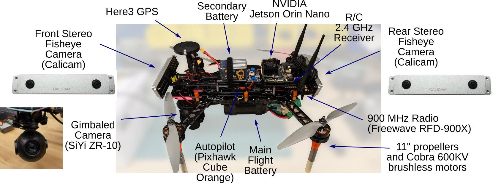
The QAV500 is a custom-built quadrotor UAV that is developed from commercial/hobby-grade UAV components and in-house 3D printed parts (see Fig. 2 and Table I). The main structure of the UAV is the QAV500 V2 H-style quadcopter frame made by Lumenier. The QAV500 V2 was chosen for its modular design, consisting of a rigid lower frame and an upper frame. Silicone bobbin dampers join the upper and lower frames, which isolate sensors from vibration. Various motor, propeller, and battery combinations were evaluated using xcopterCalc [14] to maximize efficiency and endurance, the final selection is shown in Table I. A 4in1 ESC was selected to simplify wiring. A Cube Orange autopilot running Arducopter 4.4.0 firmware is used for flight control since it is a widely adopted and well-documented system. The vehicle has a Here3 GPS with a companion Here+ RTK Base. An NVIDIA Jetson Orin Nano with an attached WiFi board provides a companion computer intended for higher-level tasks such as sensor data acquisition and processing, state estimation/odometry, path planning, autonomy, guidance, navigation, and advanced control. A 900 MHz RFD-900X radio is used for telemetry/connection with a ground station computer running QGroundControl. The drone can be remotely piloted using a Spektrum 2.4 GHz transmitter. The main battery powers the flight controller, motors, radios, and GPS, and a secondary battery powers the cameras and the companion computer through a step-down converter for an input of 19V.
| Component | Model |
|---|---|
| Frame | Lumenier QAV500 V2 |
| Frame Arms | Lumenier QAV 500mm Size G10 |
| Motors | Cobra CM4008/24, 600KV |
| Propellers | APC 11x4.5MR-B4 |
| ESC | Lumenier Elite 60A, 2-6S, 4in1 |
| Flight Controller | Cube Orange ADS-B Board |
| Main Battery | SMC Racing (LiPo, 8000 mAh, 20C, 6S) |
| Secondary Battery | Auline EX (2000 mAh, 120C, 6S) |
| GPS | Here3 GPS module |
| Radio Receiver | Spektrum SPM9745 DSMX Receiver |
| Gimbaled Camera | SiYi ZR-10 |
| Fisheye Cameras | Calicam |
| Computer | NVIDIA Jetson Orin Nano |
| Telemetry Radio | RFD-900X (900 MHz) |
The landing gear, frame edge protectors, and electronics mounts were designed using a CAD model of the UAV frame. The landing gear was printed out of PETG filament and extended with 0.5 in diameter, 3 in long PVC pipe segments press-fit into the printed landing gear. The motors and landing gear are mounted concentrically using the same bolts. Frame arm edge protectors, printed using FLEX filament, are installed under the motors. The battery mount is printed using FLEX filament and serves to prevent the battery from sliding during flight and to protect the battery from exposed screws. The GPS mount is 3D printed out of PETG plastic and consists of a clamping swivel and a tower. Double-sided adhesive tape secures the GPS to the tower. The tower then connects to a clamping swivel with detents that allow the GPS to be locked into an upright position for use and a forward-facing lowered position for storage, allowing multiple UAVs to be stacked.
The weight of the assembled platform, with minimum instrumentation required for flight, is 2.8 kg and has a diagonal dimension of 50 cm. The endurance and range of the platform were predicted using the xcopterCalc [14] performance calculator (Table II) both with and without the weight and current draw of optional vehicle payloads (including cameras, NVIDIA computer, and secondary batteries). The exact model of the ESC was not available in the xcopterCalc database and an approximated model was used instead. The ESC parameters were set to 60 A for continuous current capacity, 100 A for maximum current capacity, a general resistance of 0.0025 , and a weight of 20 g, per the manufacturer’s specifications. Models of all other chosen parts were available. Approximated values of flight endurance and range assuming a standard model of drag at various airspeeds are shown in Table II. No limit was set for the maximum vehicle tilt allowed by the flight controller in this analysis. The fully instrumeted UAV weighs 4.1 kg and costs approximately $1120.
| Base Platform | With Payload | |||
|---|---|---|---|---|
|
Airspeed
(km/h) |
Endurance (sec) | Range (m) | Endurance (sec) | Range (m) |
| 0 | 1122 | 0 | 618 | 0 |
| 10 | 1080 | 3000 | 600 | 1667 |
| 20 | 900 | 5000 | 530 | 3000 |
| 30 | 825 | 5700 | 440 | 3667 |
| 35.5 | 570 | 5650 | 385 | 3834 |
| 40 | 500 | 5500 | – | – |
| 46 | 400 | 5200 | – | – |
II-B Target Tracking Sensor and Autonomous Behavior
This SiYi ZR10 Gimbal Camera is a low-cost gimbaled camera that supports two-axis (pan/tilt) motion and can be controlled directly using MAVLINK commands to point at a desired latitude and longitude. A two-position switch on the radio controller starts/stops the recording. The video feed is recorded to an onboard micro SD card or can be streamed using ethernet to the NVIDIA Orin via RTSP. The sensors connected to the autopilot (accelerometers, gyros, compasses, and GPS) are logged on the autopilot’s black-box SD card.
Target tracking requirements are often specified by altitude and standoff distance relative to the target. The standoff distance can be achieved in many ways, for example, by continuously orbiting a target, or tracking it from a particular orientation relative to the target velocity (i.e., so the target appears in the same orientation on the video feed). Perhaps the simplest tracking approach, and the one used in this work, is to hold a fixed relative position to the target. To command a constant relative position that is directly overtop of the target, we utilize dronekit [15] to send MAVLINK messages. A latitude/longitude coordinate of a moving ground target is set as the desired waypoint for the UAV and the desired target pointing position for the gimbal. Presently, the target latitude/longitude is directly provided by the target itself (transmitted over the 900 MHz radio). This provides an automated capability to collect visual tracking data and test algorithms using perfect knowledge of the target’s position (as an example, see Fig. 1). In future work, this will be replaced with an online estimate of the target position derived from onboard imaging sensors.
II-C Mapping Sensors and Related Perception Algorithms
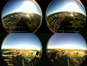
The Calicam [16] fisheye stereo cameras were chosen as the perception sensor used for mapping and hazard detection. The CaliCam is an electronic rolling shutter camera that has a 12 cm baseline, a 200∘ horizontal field of view, a pixel size of 3.75 x 3.75 m, and a resolution of 2560 x 960 at 30 Hz. The wide field of view, precise factory calibration, and compact and low-cost design made it an ideal choice. The cameras were mounted on the front and rear of the UAV using PETG mounts that were inclined downward at angles. This arrangement provides a nearly omnidirectional view that minimizes blind spots. The cameras are designed with a long baseline configuration, wherein the two cameras are positioned parallel to each other with an equivalent pointing direction and fixed horizontal separation, simplifying mapping tasks such as triangulation and disparity calculations. An example of the CaliCam imagery is shown in Fig. 3. While the fisheye cameras are the main mapping sensors, the gimbaled camera can also be used for mapping.
II-D Data Collection Computer
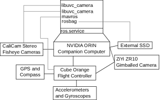
The UAV is equipped with an NVIDIA Orin computer that can be used for data collection, and running autonomy and perception algorithms. The Pixhawk Cube autopilot is connected to the NVIDIA Orin via a UART connection, and the CaliCams are connected to the NVIDIA Orin via high-speed USB 2.0 cables. To synchronize all of the data streams, the NVIDIA Orin uses the Robot Operating System (ROS) to synchronize the data streams’ timestamps. The three main ROS nodes running on the NVIDIA Orin are MAVROS—an intermediary that converts MAVLink messages to ROS messages—and two libuvc_camera nodes—a node that connects to most USB cameras. To record the desired data streams, the rosbag command writes ROS topics to a drive. The amount of information coming from the CaliCams with full resolution was too high for the USB-C solid-state hard drive to write, so the CaliCams’ resolution was reduced from 2560 x 960 to 1280 x 480 which allowed for all of the data to be captured. To start the ROS system two Linux services were created, one as the super user to modify permissions for the CaliCam USB ports and run any startup tasks, and a second as a regular user to call the ROS launch file to start the ROS nodes. These services automatically start while the NVIDIA Orin is booting. For a diagram of the hardware connections and ROS nodes refer to Fig. 4.
III Experimental Characterization of Quadrotor Capabilities
III-A Quadrotor Performance Characterization
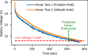
Two hover tests were performed to determine the safe hovering time of the UAV, which was determined to be about 11 min based on the battery voltage drop observed in Fig. 5 (the flight battery cutoff is a 3.6V cell average). In the first trial, a pilot held a constant altitude while in position hold flight mode (the UAV maintains a fixed horizontal position and the pilot controls the altitude). In the second trial, an identical battery was used and the UAV was in altitude hold flight mode with a target altitude of 2 m. The UAV’s altitude varied by approximately 1.5 m during the automated altitude hold test and by less than 0.5 m in the position hold test.
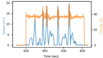
Another experiment was carried out to determine the maximum speed of the UAV. For this test, the maximum pitch/roll angle in the autopilot settings was changed to 45∘ and the vehicle was flown manually in a straight line. Fig. 6 shows a plot of the throttle and horizontal speed. Due to constraints in the test area, the throttle was limited to less than 50%, and at this throttle setting a speed of 19.8 m/s was achieved. Other performance metrics for the QAV are estimated by the xcopterCalc [14] and shown in Table III.
| Parameter | Value |
|---|---|
| Hover flight time | 10.4 min. |
| Thrust-weight ratio | 1.7:1 |
| Specific thrust | 5.23 g/W |
| Per motor current draw at hover | 9.11 A |
| Per motor power consumption at hover | 196 W |
| Total power consumption at hover | 676.7 W |
| Efficiency at hover | 83.7 % |
| Linear throttle position at hover | 66 % |
| Per motor current draw at max throttle | 20.77 A |
| Per motor power consumption at maximum throttle | 429.9 W |
| Total power consumption at maximum throttle | 1475.2 W |
| Efficiency at maximum throttle | 80 % |
| Maximum speed | 18.06 m/s |
| Maximum rate of climb | 6 m/s |
III-B Quadrotor Noise Characterization
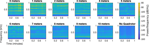
A UAV operating in an urban environment at a relatively low altitude generates significant noise that can be undesirable to bystanders. Characterizing the baseline noise generated by the UNC Charlotte QAV500 drone provides information to model the observed level of the noise on the ground at different UAV altitudes. An experiment was conducted on the UNC Charlotte campus with a UAV in a fixed hovering position at 5 m altitude. One-minute length audio recordings were collected from zero to ten meters in one-meter intervals by moving a tripod with a mounted Dayton Audio UMM-6 microphone (frequency response 20 kHz). Onboard telemetry recorded drone states, including altitude, position, and motor RPM. A control data set (with no UAV) and a ground-level data set were also recorded. Spectrograms visually representing the energy content of frequencies in the 10 Hz-1kHz range over time as shown in Fig. 7. The sound intensity of the UAV decreases with horizontal distance. The spectrogram displays a pattern of high energy frequency bands corresponding to the motor RPM, blade frequency, and their harmonics.
III-C Quadrotor Communication Range Characterization
The UAV can potentially utilize three forms of communication with the ground station operators (WiFi, 900 MHz radio, and 2.4 GHz transmitter). Communication interruptions can lead to loss of vehicle control and characterizing the range of the communication systems through testing allows for increased safety and more reliable mission planning. Range testing was conducted on UNC Charlotte’s campus with all three of the aforementioned communication channels while recording RSSI (dBm) and GPS data. Figure 8 illustrates the change in radio strength over distance during these tests. Note that the WiFi module used in this experiment was comparable to but not the same as the one used on the NVIDIA Jetson Orin Nano. The graphs show that a range of dBm to dBm for the transmitter, dBm to dBm for the WiFi, and dBm to dBm for the radio modem is suitable for reliable communication. The radio modem has the longest range of communication. A sharp decrease in signal strength is evident across all three communication modes during the beginning of the experiment, but the decrease levels out at the end of the experiment. At around -70 to -80 dBm range, the signal strength became approximately constant for the R/C transmitter. Longer-range pilot transmitters and elevated antenna poles are being considered for future operations.
III-D Mapping and Tracking Flight Demonstration
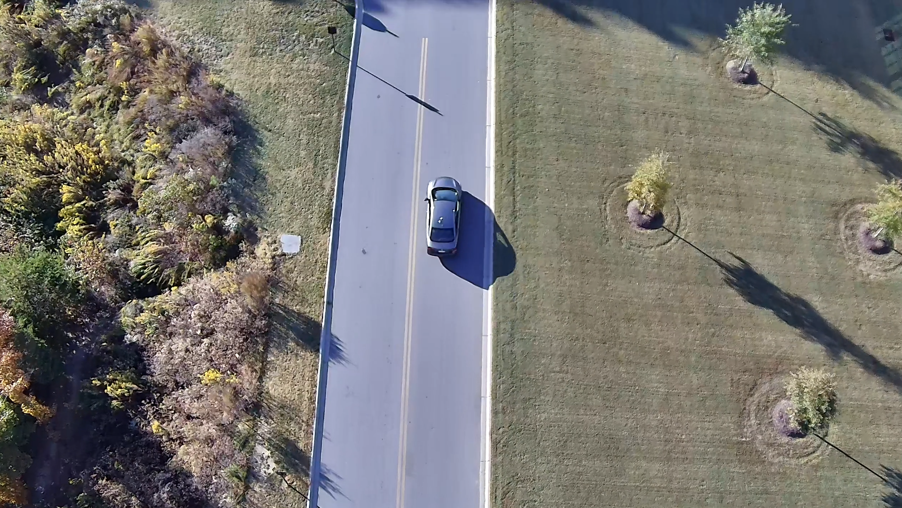
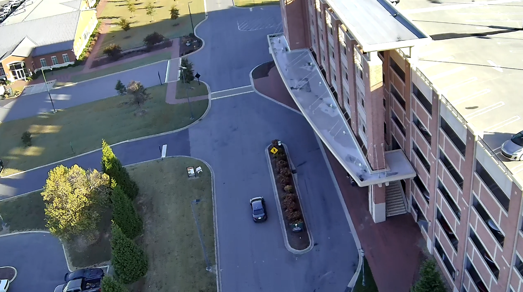
A flight test was conducted on October 26, 2023 on UNC Charlotte’s campus to demonstrate the target tracking and mapping capabilities of the UAV. The test was conducted from the roof deck of a five-story parking garage at Poplar Lane, Charlotte, NC (latitude/longitude: 35.31389∘, -80.73175∘).
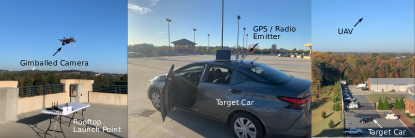
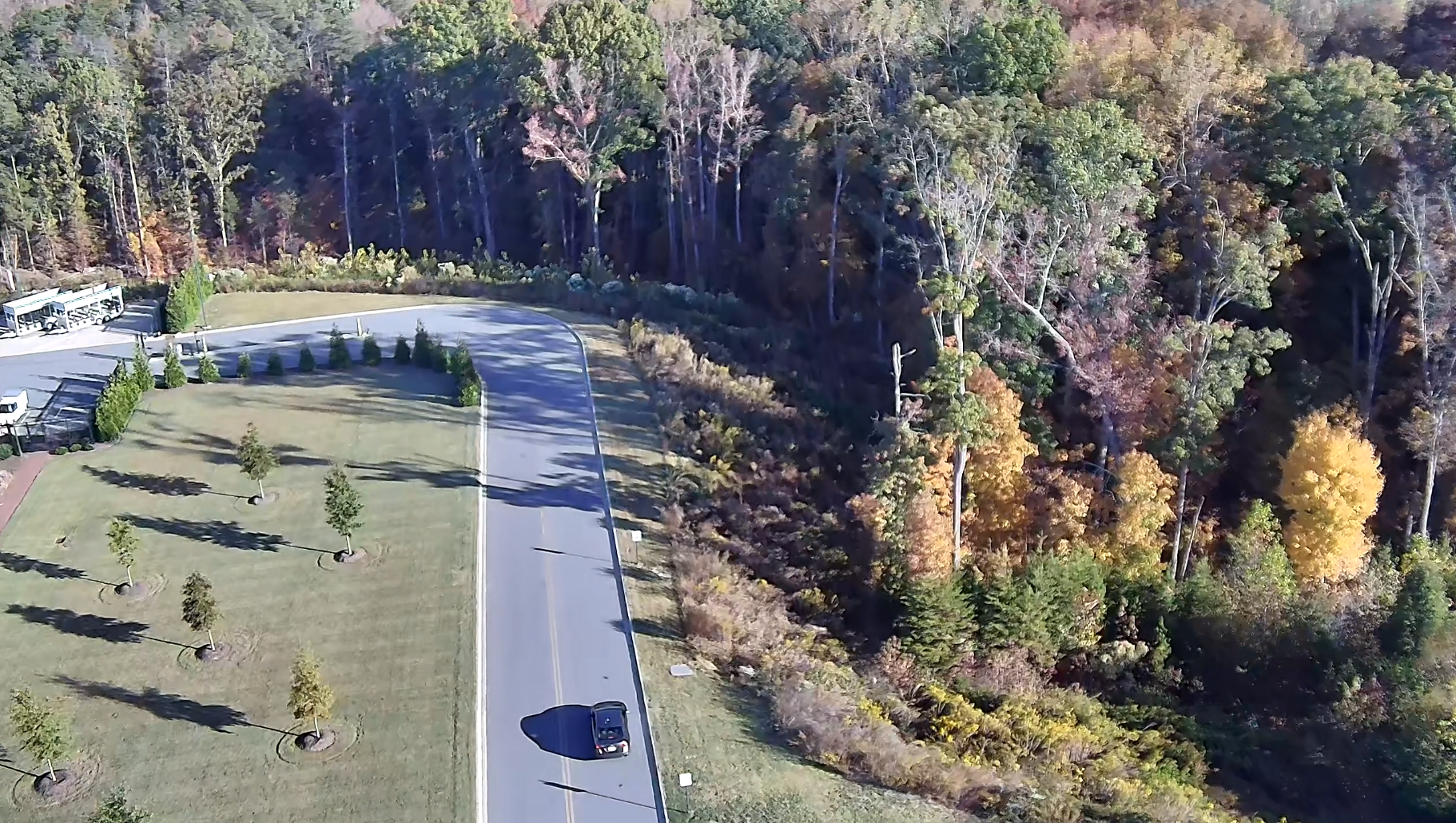
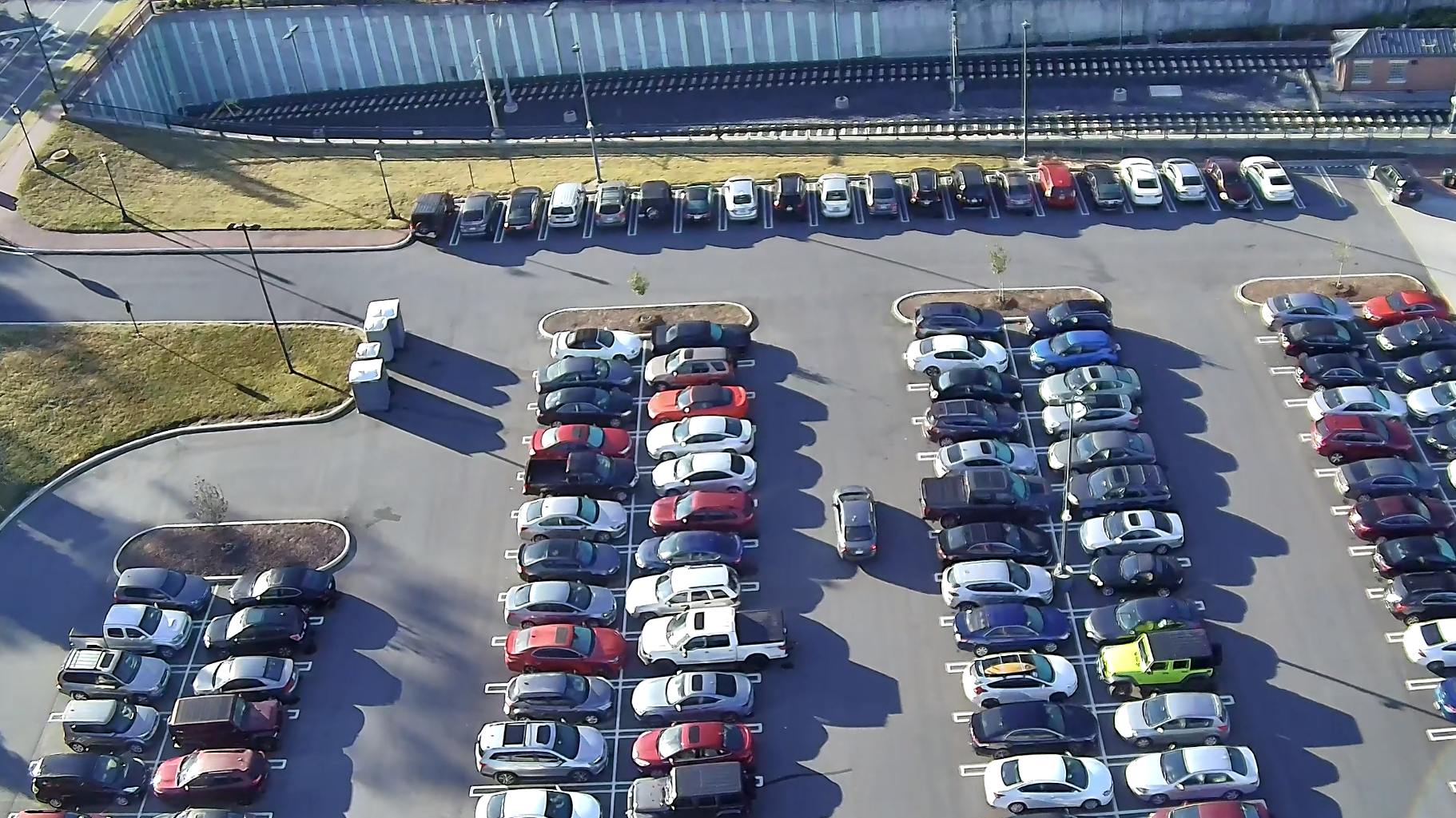
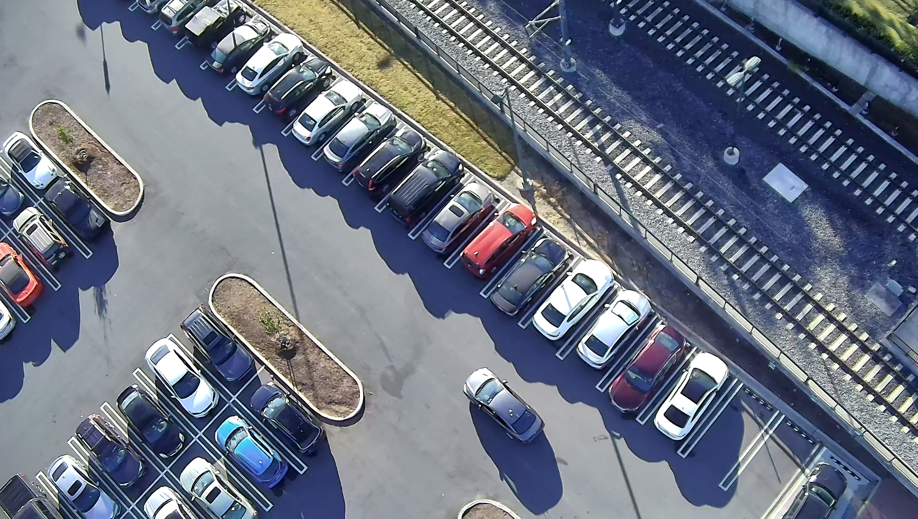
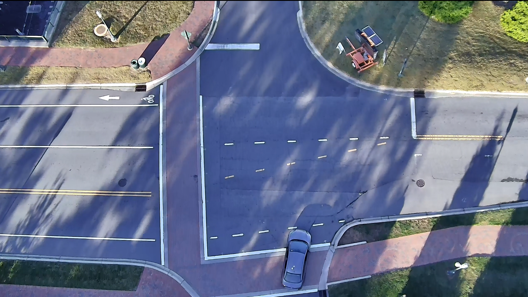
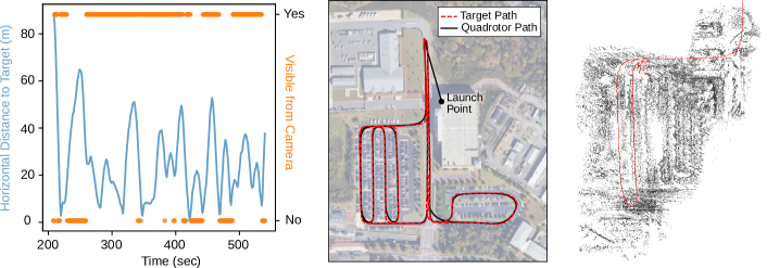
This location provides the pilot with a clear view of the UAV during tests. The flight test was designed to test the target tracking capability as well as fisheye imagery collection and mapping. The experiment setup is shown in Fig. 9. A target vehicle was outfitted with a roof-mounted 900 MHz antenna, GPS unit, and laptop, to broadcast UAV desired waypoints while in motion. After launch, the UAV was commanded to continuously follow directly over the top of the vehicle and point the gimbal at the vehicle location. Once the UAV was hovering above its launch point the car initiated transmission of drone waypoints and gimbal pointing coordinates read from the car-mounted GPS unit. The UAV tracked the target for approximately 5.5 minutes. Example imagery collected is shown in Fig. 1. The UAV had a maximum velocity constraint set at 8 m/s and the altitude corresponded to a standoff distance of approximately 55 meters. The UAV tracked the car through two different parking lots and along the road, Fig. 10. The UAV stayed within 60 meters of the target car during the test and kept the target in the gimbal camera image 72.3% of the time from manual video analysis.
.
Follow-on work should also consider adding additional control logic to keep track of how close the gimbal is to its mechanical limits and perform maneuvers to avoid hitting this limit (causing the gimbal to “unwind”). Another question to be explored in future work is the joint optimization of vehicle motion and gimbal motion—that is, when should the vehicle move to improve the view of the target versus rotate the gimbal and/or how to perform this maneuver optimally.
Fig. 10 illustrates the mapping capability of the UAV by applying the state-of-the-art DSO (Direct Sparse Odometry) algorithm [17] to the imagery collected during the experiment. DSO is a visual odometry technique that adapts Structure-from-Motion (SfM) methods for 3D reconstruction. It estimates the camera motion and the sparse 3D structure of the environment from a sequence of 2D images by minimizing photometric errors. Our implementation adhered to the original configuration [17] with the default parameters. The point cloud visualizes the parking lot’s structure, while the red curve represents UAV odometry, and the pyramid symbolizes the current pose of the gimbaled camera. It is important to note that DSO is not optimized for cameras with frequent and constant pose changes, such as gimbaled cameras. Consequently, achieving highly optimized reconstructions directly from gimbaled camera data poses challenges. This experiment demonstrates the mapping potential of our design and future work will utilize the stereo fisheye imagery for mapping.
IV Conclusion
This paper presented the design of a quadrotor UAV that is tailored for conducting research related to autonomous mapping, hazard avoidance, and target tracking. The platform has a unique sensor arrangement that includes 5 imaging sensors (two pairs of stereo fisheye cameras and a gimbaled camera). Various characteristics of the UAV were experimentally identified, including its endurance (11 minutes), range (3.8 km), and top speed (20 m/s). The noise level of the UAV as a function of distance was also evaluated from 0 to 10 m. The practical communication range of the onboard radios and WiFi, in the presence of obstructing buildings, was also determined. Lastly, the capabilities of the UAV to perform mapping and tracking tasks were demonstrated through a flight experiment wherein the UAV followed a GPS-tagged vehicle moving through a parking lot, and data collected was used to construct a map of the scene. The information reported may be useful to researchers developing similar systems.
In future work, we aim to enhance the UAV’s software architecture to support onboard testing of autonomous path planning, control, and perception algorithms. The platform will be used to support planned work involving tracking moving ground targets in the presence of occlusion and the use of fisheye cameras to support hazard avoidance.
References
- [1] A. Alcántara, J. Capitán, A. Torres-González, R. Cunha, and A. Ollero, “Autonomous execution of cinematographic shots with multiple drones,” IEEE Access, vol. 8, pp. 201 300–201 316, 2020.
- [2] D. C. Schedl, I. Kurmi, and O. Bimber, “An autonomous drone for search and rescue in forests using airborne optical sectioning,” Sci. Robot., vol. 6, no. 55, p. eabg1188, 2021.
- [3] B. R. Geiger, J. F. Horn, G. L. Sinsley, J. A. Ross, L. N. Long, and A. F. Niessner, “Flight testing a real-time direct collocation path planner,” J. Guid., Control, and Dyn., vol. 31, no. 6, pp. 1575–1586, 2008.
- [4] Skydio, “Skydio 2+. Navigates tight spaces nimbly. ,” https://www.skydio.com/skydio-2-plus-enterprise, 2024, accessed: 2024-01-14.
- [5] A. D. P. Cloitre, “Omnidirectional obstacle detection using minimal sensing,” Ph.D. dissertation, Massachusetts Institute of Technology, 2019.
- [6] W. Gao, K. Wang, W. Ding, F. Gao, T. Qin, and S. Shen, “Autonomous aerial robot using dual-fisheye cameras,” J. Field Robot., vol. 37, no. 4, pp. 497–514, 2020.
- [7] J. Kim, Y. Jung, D. Lee, and D. H. Shim, “Landing control on a mobile platform for multi-copters using an omnidirectional image sensor,” J. Intell. & Robotic Syst., vol. 84, pp. 529–541, 2016.
- [8] J. Pestana, J. L. Sanchez-Lopez, S. Saripalli, and P. Campoy, “Computer vision based general object following for GPS-denied multirotor unmanned vehicles,” in Proc. 2014 Amer. Control Conf. IEEE, 2014, pp. 1886–1891.
- [9] H. Cheng, L. Lin, Z. Zheng, Y. Guan, and Z. Liu, “An autonomous vision-based target tracking system for rotorcraft unmanned aerial vehicles,” in Proc. 2017 IEEE/RSJ Int. Conf. Intell. Robots and Syst. IEEE, 2017, pp. 1732–1738.
- [10] N. J. Sanket, C. M. Parameshwara, C. D. Singh, A. V. Kuruttukulam, C. Fermüller, D. Scaramuzza, and Y. Aloimonos, “Evdodgenet: Deep dynamic obstacle dodging with event cameras,” in 2020 IEEE Int. Conf. Robot. and Automat. IEEE, 2020, pp. 10 651–10 657.
- [11] D. Falanga, K. Kleber, and D. Scaramuzza, “Dynamic obstacle avoidance for quadrotors with event cameras,” Sci. Robot., vol. 5, no. 40, p. eaaz9712, 2020.
- [12] J. Tordesillas and J. P. How, “Panther: Perception-aware trajectory planner in dynamic environments,” IEEE Access, vol. 10, pp. 22 662–22 677, 2022.
- [13] X. Zhou, X. Wen, Z. Wang, Y. Gao, H. Li, Q. Wang, T. Yang, H. Lu, Y. Cao, C. Xu et al., “Swarm of micro flying robots in the wild,” Sci. Robot., vol. 7, no. 66, p. eabm5954, 2022.
- [14] M. Mueller, “ecalc - xcoptercalc - the most reliable multicopter calculator on the web,” https://www.ecalc.ch/xcoptercalc.php, 2024, accessed: 2024-12-01.
- [15] 3D Robotics, “Introducing DroneKit-Python,” https://dronekit-python.readthedocs.io/en/latest/about/index.html, 2023, accessed: 2023-08-14.
- [16] Astar.ai Inc., “CaliCam® - Calibrated Cameras — ASTAR,” https://astar.ai/pages/calicam, accessed: 2023-11-04.
- [17] J. Engel, V. Koltun, and D. Cremers, “Direct sparse odometry,” IEEE Trans. Pattern Anal. and Mach. Intell., vol. 40, no. 3, pp. 611–625, 2017.