Magnetic transitions of biphenylene network layers induced by external perturbations
Abstract
We present a comprehensive investigation of the magnetic ordering in biphenylene network (BPN) layers, employing density functional theory (DFT) calculations under external perturbations, including uniaxial strains and hole doping. We compute fully relaxed structures, energy bands, and magnetic states by performing DFT calculations augmented with extended Hubbard interactions, encompassing both on-site and inter-site interactions, to accurately capture electron correlations. We emphasize the importance of the extended Hubbard forces by contrasting BPN layers with and without the forces. Our results reveal that in their fully relaxed structures, both BPN monolayer and bilayer are non-magnetic. We exploit external perturbations to induce magnetic ordering. The application of uniaxial strains induces magnetic phase transitions, leading to ferrimagnetic and antiferromagnetic states in BPN monolayer and bilayer, respectively. Additionally, we investigate hole doping as an alternative mechanism for inducing magnetic transitions. Our findings shed light on the tunability of magnetic properties in BPN layers through external perturbations, demonstrating the promise of low-dimensional materials in future spintronics and nanoelectronic applications.
I Introduction
Recently a new planar carbon allotrope has been experimentally synthesized on the Au(111) surface throughout a bottom-up process Fan et al. (2021). The carbon allotrope is called biphenlyene network (BPN), which consists of octagon, hexagon, and tetragon rings of -hybridized carbon atoms. In the experiment BPN was grown as an armchair-edged nanoribbon structure whose width is up to 18 carbon atoms, but it is certainly expected to realize a large-scale two-dimensional BPN single-layer in the future. It would serve as a versatile platform to investigate fundamental physics of condensed matter systems as graphene has done so far Castro Neto et al. (2009).
The experimental realization of BPN layers has sparked significant interests in exploring their electronic, phononic, mechanical, chemical, and thermal properties Son et al. (2022); Liu et al. (2021a); Wang et al. (2022); Hamed Mashhadzadeh et al. (2022); Mortazavi and Shapeev (2022); Pereira et al. (2022); Ren et al. (2023); Demirci et al. (2022); Luo et al. (2021); Bafekry et al. (2021); Rublev et al. (2023); Liu et al. (2022); Chowdhury et al. (2022); Gorkan et al. (2022); Alcón et al. (2022); Shen et al. (2022); Xie et al. (2022); Yang et al. (2022a); Zhang and Tong (2022); Ren et al. (2022); Ge et al. (2021); Liu et al. (2023); Veeravenkata and Jain (2021); Zhang et al. (2021); Tong et al. (2022); Li et al. (2022); Xie et al. (2023); Yang et al. (2023); Liu et al. (2021b); Mane et al. (2022); Asadi et al. (2022); Su and Yeh (2022); Al-Jayyousi et al. (2022); Han et al. (2022); Chen et al. (2023); Niu et al. (2023). Recent studies Son et al. (2022); Liu et al. (2021a) have revealed that the 2D BPN lattice exhibits intriguing electronic band structures such as type-II Dirac cones Soluyanov et al. (2015), nearly flat bands, and saddle-point van Hove singularities (vHS). These characteristics are closely related to topological and correlation physics. It is confirmed that the 2D BPN lattice constitutes a topological material, hosting topologically protected boundary states Son et al. (2022); Liu et al. (2021a). Furthermore, the presence of saddle point vHS and nearly flat bands provide enhanced density of states (DOS), implying the potential emergence of correlation-related physics in the 2D BPN lattice. In this context, the possibility of magnetic ordering in a pristine 2D BPN monolayer has been investigated using the density functional theory (DFT) calculations Son et al. (2022). It is known that magnetic ordering can be induced through edge geometry modifications Kan et al. (2008); Son et al. (2006); Jung et al. (2009), defect introduction Lehtinen et al. (2004); Yazyev and Helm (2007), hydrogenation Eng et al. (2013); Zhou et al. (2009); Xie et al. (2011), and adatom incorporation Lehtinen et al. (2003) in carbon materials like graphene, but the presence of magnetism in pristine carbon materials is rare Gao et al. (2021). The 2D BPN lattice can be a promising candidate for magnetic all-carbon materials. Understanding magnetic ordering in BPN layers is crucial for their potential application as future spintronics platforms Alcón et al. (2022).
To understand correlation physics such as magnetism, it is of vital importance to consider many-body electron interactions in DFT calculations. To incorporate many-body electron correlations into DFT calculations, it is required to use advanced methods going beyond the mean-field level of the conventional correlation-exchange functionals such as the local density approximation (LDA) and the generalized gradient approximation (GGA). Correlation physics such as magnetic phase transitions can be investigated through the use of a newly developed DFT++ method Campo and Cococcioni (2010); Timrov et al. (2021, 2018); Mahajan et al. (2021); Lee and Son (2020); Tancogne-Dejean and Rubio (2020). The DFT++ method includes not only on-site Hubbard interactions (), but also inter-site interactions (), thereby capturing the intricate interplay between strong electron localization and hybridization of extended neighboring orbitals, particularly for systems featuring covalent bonding characters. Remarkably, this extended Hubbard approach has demonstrated its capability to capture the effect of Coulomb interactions in electronic structure calculations at the similar level of approximations Hedin (1965), with applications spanning not only three-dimensional solids Campo and Cococcioni (2010); Timrov et al. (2021); Tancogne-Dejean and Rubio (2020); Lee and Son (2020), but also low-dimensional materials such as graphene Tancogne-Dejean and Rubio (2020) and black phosphorus Lee and Son (2020).
When investigating possible magnetic ordering of BPN layers, one crucial consideration is accurate estimation of atomic structures. Influenced by atomic structure details, the positions of saddle-point vHS and nearly flat bands with respect to the Fermi energy are determined. To this end, accurate atomic structure predictions for BPN layers are imperative, considering electron correlations within the DFT++ method. Regarding the potential impact of extended Hubbard corrections in introducing additional forces, it is possible that lattice constants and atomic configurations may deviate from those predicted by the mean-field level of DFT calculations. Noteworthy advancements have recently focused on forces corrected by extended Hubbard terms, enabling successfully calculations of lattice dynamics with extended Hubbard interactions Yang et al. (2021, 2022b); Jang et al. (2023). The force calculation scheme, encompassing extended Hubbard forces, can be readily used to obtain fully relaxed atomic structures within the DFT++ calculations.
In this study, we conducted a comprehensive investigation into magnetic transitions of BPN layers by the DFT++ method. We undertook the relaxation of atomic structures for BPN monolayer and bilayer, employing the extended Hubbard forces. By analyzing the positions of vHS and flat bands relative to , we contrasted the electronic structures and magnetic ordering of BPN layers with and without the extended Hubbard forces. We showed that the subtle modification of the atomic structure due to the extended Hubbard forces predicts a non-magnetic state unlike the previous study Son et al. (2022). Subsequently, we explored their magnetic properties by subjecting them to external perturbations such as uniaxial strains and doping.
II Computational Details
For DFT calculations we use Quantum Espresso Giannozzi et al. (2009, 2017) with the plane-wave (PW) basis, the PBE exchange-correlation functional Perdew et al. (1996) and norm-conserving pseudopotentials Hamann (2013); van Setten et al. (2018). We also use a van der Waals (vdW) correction known as rev-vdW-DF2 Hamada (2014); Kim et al. (2017). We adopt -point mesh, and the kinetic energy cutoff Ry for self-consistent calculations. To prevent interactions between periodic image layers, a vacuum region with a size of 15 Å is employed. To incorporate many-body electron correlations, we employed the DFT++ method recently implemented in Quantum Espresso Lee and Son (2020), where on-site and inter-site Hubbard interactions are self-consistently determined by using the Hartree-Fock formalism based on the pseudohybrid Hubbard density functional known as ACBN0 Agapito et al. (2015). All atomic structures are relaxed to ensure that all components of forces acting on atoms are below 0.051 eV/Å. Note that we call conventional DFT calculations with GGA functionals as DFT-GGA in order to distinguish against the DFT++ method.
III Results and Discussion
| monolayer | |||||||||||
|---|---|---|---|---|---|---|---|---|---|---|---|
| DFT-GGA | 4.52 | 3.77 | 1.46 | 1.46 | 1.45 | 1.41 | |||||
| DFT++ | 4.47 | 3.80 | 1.41 | 1.51 | 1.46 | 1.40 | |||||
| bilayer | |||||||||||
| DFT-GGA | 4.52 | 3.77 | 1.46 | 1.46 | 1.45 | 1.41 | 3.24 | 3.28 | |||
| DFT++ | 4.47 | 3.81 | 1.41 | 1.51 | 1.47 | 1.40 | 3.48 | 3.48 |
III.1 Relaxed structures
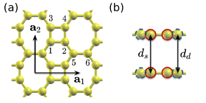
First we compare the atomic structures of both the BPN monolayer and bilayer, which are relaxed using DFT-GGA calculations as well as the DFT++ method. Figure 1 illustrates the atomic configurations of BPN layers. The BPN lattice layer contains six carbon atoms in the unit cell. As depicted in Fig. 1(a), the carbon atoms are labeled accordingly, with atoms 1 to 4 forming a square cluster, and atoms 5 and 6 forming a dimer. For the monolayer BPN, all six atoms reside within the same plane, without any out-of-plane displacement. The BPN lattice exhibits a pattern consisting of square, hexagon, and octagon rings. Additionally, when stacking BPN layers, each layer precisely aligns on top of its neighboring layer, as demonstrated in Fig. 1(b).
Table 1 presents a comparison of lattice constants and atomic configurations of BPN lattices, which are relaxed using GGA and DFT++ methods. With the inclusion of + corrections, the lattice constant decreases from 4.52 Å to 4.47 Å, while the lattice constant increases from 3.77 Å to 3.80 Å. Consequently, the DFT++ method predicts that a square with DFT-GGA is transformed to the rectangle cluster, experiencing contraction along the -axis and elongation along the -axis. Furthermore, the size of the dimer slightly increases by 0.02 Å.
For the BPN bilayer, the energy minimum configuration is the on-top stacking where the upper layer is exactly on the top of the lower layer as shown in Fig. 1. both DFT-GGA and DFT++ calculations indicate the intra-layer configurations remain the same as those of the monolayer. However, the inclusion of + corrections leads to changes in inter-layer configurations. In the DFT-GGA calculations, carbon atoms in the bilayer exhibit small out-of-plane displacements. The inter-layer distances between atoms in the square cluster and the dimer, denoted as and respectively, are found to be Å and Å as indicated in Fig. 1(b) and Table 1. When + corrections are incorporated, the inter-layer distance undergoes an increase of approximately 0.24 Å, and out-of-place displacements disappear.
III.2 Band Structures
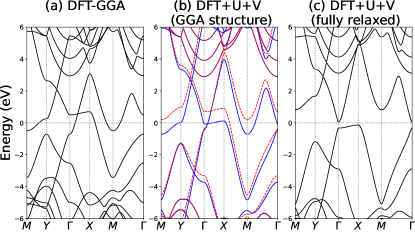
We observed distinct electronic structure properties of monolayer BPN, predicted by DFT-GGA and DFT++ calculations, as demonstrated in Fig. 2. We reproduced the DFT-GGA electronic band structures as reported Ref. Son et al. (2022); Demirci et al. (2022). DFT-GGA calculations reveal a saddle-shaped band hosting the van Hove singularity (vHS) at , intersecting with the nearly flat band around in Fig. 2(a). The band structures in the vicinity of the crossing point exhibit a type-II Dirac state Soluyanov et al. (2015); Yan et al. (2017); Armitage et al. (2018); Fei et al. (2017); Noh et al. (2017). The nearly flat band is mainly composed of orbitals localized on the square cluster. The saddle-shaped band is formed by the combination of orbitals on the square unit and the dimer, with the main contribution coming from orbitals of the dimer. An additional remarkable feature of the band structure is the presence of a saddle-shaped band that hosts another vHS near the point around .
Next we perform DFT++ calculations using the atomic structure relaxed by DFT-GGA, in order to differentiate them from the full DFT++ calculations where atomic structures are entirely relaxed using + corrections. Here we call the atomic structures relaxed by DFT-GGA as GGA structures. The self-consistent calculations of onsite () and inter-site () Hubbard interactions are eV, eV, eV, eV, and eV, where and denote the tetragon and the dimer respectively and atomic site numbers in inter-site interactions follow Fig. 1(a). In comparison with DFT-GGA calculations, the inclusion of + corrections leads to increased overall bandwidths of the resulting band structures. The DFT++ calculations with GGA structures reveal a ferrimagnetic ground state for the single-layer BPN, where the square unit and the dimer possess opposite magnetic moments. For example, Fig. 10(a) represents spin polarization density of the ferrimagnetic phase, where and are spin-up and spin-down densities, respectively. Since their magnetic moments do not completely cancel out, monolayer BPN exhibits a net magnetic moment. Figure 2(b) illustrates the spin-resolved band structures of the ferrimagnetic ground state, displaying opposite spin orientations. In comparison to DFT-GGA band structures, vHS moves closer to , and one nearly flat band at shifts downwards towards . Accordingly, among four crossing points between two saddle-shaped bands and two nearly flat bands, two of them are located in the vicinity of -point and have energies close to .
However, when the atomic structure is fully relaxed with the DFT++ method, the corresponding band structures exhibit different electronic properties compared to DFT++ calculations with GGA structures. Firstly, the resulting ground state is non-magnetic, which is in contrast to the fact that the DFT++ calculations with GGA structures predict a ferrimagnetic ordering. Secondly, as illustrated in Fig. 2(c), a band gap opens at the zone center even in the fully relaxed structure without external perturbations such as strains and doping. It is found that the band edge minimum at moves upward above , resulting in the single layer BPN being a semiconductor with an indirect band gap between the conduction band bottom at and the valence band top at . We also note that the self-consistent Hubbard interactions for the full DFT++ calculation are eV, eV, eV, eV, eV, and eV.
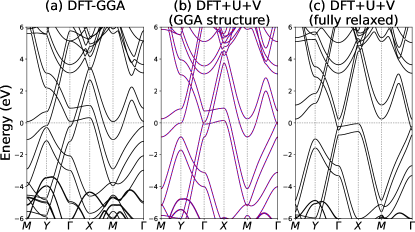
We extend our discussions to electronic band structures of bilayer BPN, comparing DFT-GGA calculations and DFT++ ones. In the DFT-GGA calculations, bilayer BPN is found to be non-magnetic. The resulting band structures, as shown in Fig. 3(a), exhibit two nearly flat bands along direction and two bands hosting vHS at the point. These bands intersect at four points along .
Using atomic structures relaxed by DFT-GGA (GGA structures), DFT++ calculations reveal that bilayer BPN exhibits an antiferromagnetic ground state. Each layer displays a ferrimagnetic order similar to monolayer BPN in the same calculation condition, but the upper and lower layers possess opposite spin orientations. The self-consistent evaluations of Hubbard interactions are eV, eV, eV, eV, and eV, which are almost the same with those of monolayer BPN in DFT++ calculations with GGA structure. The band structures from DFT++ calculations using the GGA structures, as depicted in Fig. 3(b), show each band to be doubly degenerate with opposite spin configurations. The crossing point between the upper band with vHS and the lower flat band is annihilated with its time-reversal partner at , so there are three type-II Dirac points.
Fully relaxed the atomic configuration with the DFT++ method, the bilayer BPN reverts to a non-magnetic state. In Fig. 3(c), all type-II Dirac points merge with their time-reversal partners, leaving no type-II Dirac point remaining. Around , there are two V-shaped bands on the conduction side and two trapezoid-shaped valence bands, which include flat bands on . Unlike monolayer BPN, the bilayer BPN is metallic due to overlap between lower V-shaped band and upper flat band around . Note that the self-consistent Hubbard interactions for the full DFT++ calculation for bilayer BPN are the same with those of monolayer BPN.
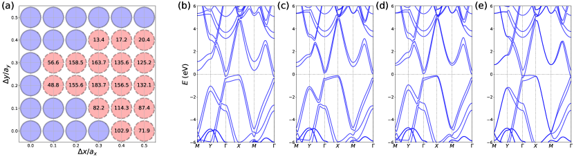
We also consider electronic structures of other stacking configurations as well as the energy-minimum on-top configuration. We shift the and positions of the upper layer relative to the lower layer by and . Depending on and , it is found that bilayer BPN can be either metal or semiconductor, whose band gap is about from 10 meV to 200 meV as shown in Fig. 4(a). Regardless of stacking configurations, bilayer BPN remains non-magnetic.
III.3 Magnetic transitions
It is shown that monolayer and bilayer BPN fully relaxed within the DFT++ method are non-magnetic, which is in contrast to the fact that monolayer and bilayer BPN exhibit magnetic ordering when the DFT++ method is employed with GGA structures. The key distinction arises from the relative positions of intriguing electronic structures such as nearly flat bands and saddle-point vHS with respect to . This observation suggests a strategy to induce magnetic ordering in BPN layers: Tuning positions of nearly flat bands and saddle-point vHS, which can be achieved through external perturbations like uniaxial strains and hole doping.
III.3.1 Uniaxial strains
We investigate the impact of uniaxial strains on the magnetic transitions of monolayer and bilayer BPN. External strains cause shifts in the positions of vHS and flat bands relative to , potentially leading to magnetic transitions. We observed that the GGA structure, which possesses a larger lattice constant than the DFT++ structure, exhibits magnetism with the + correction. This observation suggests that enlarging the unit cell may induce a magnetic transition.
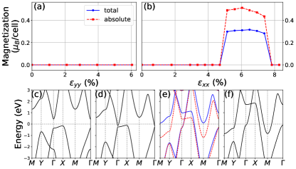
Figures 5(a) and (b) present total and absolute magnetization as a function of and , respectively. Here the uniaxial strain () along () direction is expressed as (), where and represent the lattice constants along and directions without external strains, respectively, as summarized in Table. 1. When uniaxial -strains are applied, we find that they do not induce a magnetic transition. For example, as shown in Fig. 5(c), the band structures at % demonstrate that uniaxial strains lead to an enhancement of the band gap opening around , resulting in a lack of DOS involved in the magnetic transition.
In contrast, uniaxial strains along direction can trigger a transition from a non-magnetic state to a ferrimagnetic one. The magnetic transition to a ferrimagnetic phase is observed at %. For smaller , type-II Dirac points are annihilated with vHS, leading to the opening of an energy gap at . For example, at in Fig. 5(d), a small energy gap is observed at . However, as increases above 4.90 %, Dirac points and vHS reappear around , causing the energy gap at to close. At the same time, vHS at and the conduction band edge at move downward to .
The ferrimagnetic phase, characterized by total magnetization being smaller than absolute one, persists up to % as shown in Fig. 5(b). For the ferrimagnetic phase, energy bands associated with opposite spin orientations are lifted, for example, as illustrated in Fig 5(b) for %. Beyond the strain level %, the single-layer BPN returns to a non-magnetic state. At strains higher than 7.60 %, the two vHS points at and are located near , while the flat band on moves further away from . For example, see Fig. 5(f).
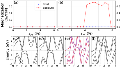
Under uniaxial strains, bilayer BPN undergoes magnetic transitions similar to the single-layer case. uniaxial strains eliminate the small overlap between the lower V-shaped band and the upper flat band present in the fully relaxed structure, eventually leading to a semiconducting state with an indirect band gap. See Fig. 6(c). No magnetic transition is observed as the DOS vanishes around .
Under the application of uniaxial strains, the bilayer BPN undergoes an antiferromagnetic transition, where the upper and lower layers have opposite spin orientations, resulting in the absence of total magnetization, for example, as shown in Fig. 10(b). The magnetic transition takes place at %, which is smaller than the transition strain observed for the monolayer BPN. When %, at which bilayer BPN is non-magnetic, some of type-II Dirac points and vHS around are partly restored, as illustrated in Fig. 6(d) where %. Around the transition strain , all four crossing points between two flat bands and two saddle-shaped bands are fully recovered. For %, the bilayer BPN becomes antiferromagnetic, and this antiferromagnetic ordering persists up to . We also note that the two flat bands on shift upward, and the conduction bands around and move down, as increases.
Note that we also consider other mechanical perturbations such as biaxial strains and in-plane and out-of-plane hydrostatic pressure. Applying biaxial strains up to 10 % and in-plane hydrostatic pressure (up to 10% lattice shrinkage), we do not observe magnetic transitions. Using out-of-plane hydrostatic pressure on bilayer BPN, we find no magnetic transition with interlayer distance reduction up to 1.6 Å.
III.3.2 Hole doping
Considering that flat bands on are below [Figs. 2(c) and 3(c)], hole doping might induce magnetic transitions by aligning the flat bands around . To investigate this scenario, we performed DFT++ calculations with different hole doping concentrations in single-layer and bilayer BPN, as shown in Figs. 7 and 8.
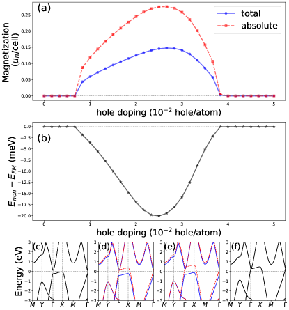
Figure 7(a) presents that single-layer BPN becomes ferrimagnetic at a hole doping concentration hole per atom. In the ferrimagnetic phase, spins of rectangle clusters and dimers are oriented in opposite directions, similar to the ferrimagnetic ordering induced by uniaxial strains. The ferrimagnetic ordering is maintained up to about hole per atom.
The band structures near show different evolutions for hole doping, compared to uniaxial strains. In the case of uniaxial strains, the ferrimagnetic phase transition is typically accompanied by the full restoration of type-II Dirac points and vHS around , as shown in the previous section. However, the ferrimagnetic state induced by hole doping has different band structures around depending on spin orientations. For example, as shown in Fig. 7(d), the energy bands associated with one spin direction exhibit a saddle point at and Dirac points with the flat band on located above . Conversely, no Dirac point or vHS are recovered in the band structures with the opposite spin orientation. Additionally, it is worth noting that overall band structures, including the other vHS at and conduction band edges at , move upwards relative to as hole doping concentrations increase. This is in contrast to the case of uniaxial strains, where band structures around evolve in the opposite direction compared with those on .
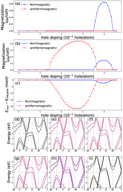
Hole doping also induces magnetic transitions in bilayer BPN, as illustrated in Fig. 8. The critical hole doping concentration for the antiferromagnetic transition is hole per atom, which is larger than that of single-layer BPN. An interesting feature of hole-doped bilayer BPN is another magnetic phase transition from antiferromagnetic ordering to ferrimagnetic one at a higher hole doping concentration hole per atom. In the ferrimagnetic state of bilayer BPN, each layer has ferrimagnetic ordering, where spins of rectangle clusters are aligned oppositely to those of dimers, which is the same as ferrimagnetic single-layer BPN. However, when considering spins at the same positions in the upper and lower layers, they are oriented in the same direction, as shown in Fig. 10(c).
Similar to hole-doped single-layer BPN, the magnetic transitions in hole-doped bilayer BPN are not associated with the full recovery of type-II Dirac points and saddle-shaped bands around , as shown in Figs. 8(d)-(i). The type-II Dirac point is formed on the upper flat band on , while the lower flat band does not host a type-II Dirac point. For the ferrimagnetic state, energy bands associated with opposite spins are split, resulting in four flat bands on in Fig. 8(h).
III.3.3 Magnetic interactions
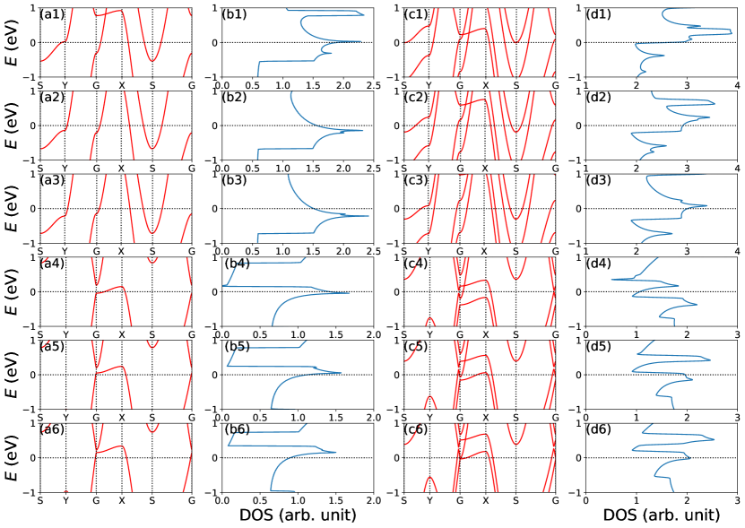
Given that the monolayer and bilayer of BPN are metallic, their magnetic behavior can be attributed to the Stoner-type magnetism of itinerant electrons in the metallic system Stoner (1938); Lidiard (1953); Lidiard and Coulson (1954); Tredgold (1954); Rice (1970); Shimizu (1984). As shown in the band structures, monolayer and bilayer of BPN have distinctive features in the electronic structure: nearly flat bands on and saddle-point vHSs at and . These features contribute to an increased DOS that can lead to the Stoner-type magnetism of itinerant electrons. To investigate this, we calculate the DOS around for monolayer and bilayer of BPN with uniaxial strains and hole doping Yates et al. (2007).
As illustrated in Fig. 9, the DOS exhibits different behaviors when monolayer BPN under uniaxial strains and hole-doped monolayer are compared. When uniaxial strains are applied, saddle points at and move close to , while the nearly flat band shifts away [See Figs. 9(a1)-(a3)]. As a result, the DOS near primarily originates from the two saddle points as shown in Figs. 9(b1)-(b3). It is known that a saddle point of 2D band structures gives rise to the logarithmically divergent DOS Rice and Scott (1975). As seen in Figs. 9(b1)-(b3), the DOS exhibits two sharp peaks, whose energies correspond to the saddle points at and . The peaks have long logarithmic tails. In contrast, hole-doped monolayer BPN shows enhanced DOS near due to the nearly flat band on . Since this nearly flat band merges with the saddle point at , the DOS peak at has a logarithmic tail on the lower side of the DOS peak. For bilayer BPN, the contributions to the DOS, despite the doubled number of nearly flat bands and saddle points, are similar to monolayer BPN under uniaxial strains and hole doping.
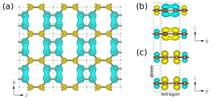
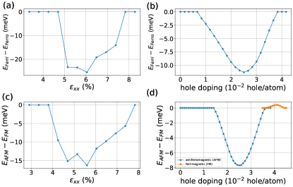
Lastly, to explore magnetic interactions between magnetic moments, we perform constrained magnetization calculations Xiang et al. (2013, 2011); Hong et al. (2022). In this calculation, we maintain the magnitude of magnetic moments, but opposite magnetic moments are flipped so that all magnetic moments are aligned in the same direction. As discussed before, monolayer BPN with an appropriate strain and hole doping displays ferrimagnetic ordering, where majority magnetic moments at the tetragon and minority ones at the dimer unit are aligned in opposite directions. For instance, the spin polarization density at % are depicted in Fig. 10(a). We denote as the total energy of the ferromagnetic ordering, where minority magnetic moments at the dimer are flipped in the constrained magnetization calculation. Comparing the total energy of the ferrimagnetic phase, we calculate the total energy difference as a function of -strain and hole doping in Figs. 11(a) and (b). This calculation shows that the transition from the ferrimagnetic phase to the ferromagnetic one requires a positive energy cost, with a maximum of 25 (10) meV, depending on ().
In the case of bilayer BPN, each layer exhibits ferrimagnetic ordering similar to monolayer BPN. In the antiferromagnetic (AFM) phase of bilayer BPN, the lower and upper layers display opposite magnetic moments, as depicted in Fig. 10(b). To be specific, the magnetic moments of the tetragon (dimer) unit in the lower layer have the same magnitude as those in the upper layer, but their directions are opposite. We perform constrained magnetization calculations where the magnetic moments of the tetragon (dimer) in the lower and the upper layers are aligned in the same direction and the ferrimagnetic ordering within each layer is fixed, which is referred to as the ferrimagnetic (FM) ordering of bilayer BPN. Denoting the resulting total energy as , Figs. 11(c) and (d) illustrate the total energy difference for bilayer BPN under uniaxial strains and hole doping. The flipping of interlayer magnetic moment from the antiferromagnetic phase to the ferrimagnetic one requires an energy cost, suggesting the stability of the antiferromagnetic ordering in bilayer BPN. In the previous subsection, the highly hole-doped bilayer BPN ( hole per atom) exhibits ferrimagnetic ordering, as depicted in Fig. 10(c). In this case, we compute the total energy of the antiferromagnetic ordering in the constrained magnetization calculations, and compare and as shown in Fig. 11(d). For the high hole-doping concentration, the calculation reveals that the ferrimagnetic ordering is energetically more favorable than the antiferromagnetic one, but their total energy difference is less than approximately meV.
IV Conclusions
In this study, we examined the magnetic transitions of monolayer and bilayer BPN, under the influence of external perturbations such as uniaxial strains and hole doping. To account for electron correlations, we employed the DFT++ method, which incorporates on-site and inter-site interactions as extended Hubbard corrections. These extended Hubbard corrections were consistently applied throughout all DFT calculations, encompassing structure relaxations and electronic band structure calculations.
Our findings indicate that both the BPN monolayer and bilayer, in their fully relaxed structures, exhibit non-magnetic behavior. However, the application of uniaxial strains along the dimer unit direction induces a ferrimagnetic transition in the monolayer, whereas the bilayer experiences a magnetic transition towards an antiferromagnetic phase.
Furthermore, we explored an alternative approach for inducing magnetic transitions in BPN monolayer and bilayer through hole doping. At a moderate level of hole doping, the monolayer assumes a ferrimagnetic phase, while the bilayer adopts an anti-ferrimagnetic state. At increased hole doping levels, the bilayer demonstrates the potential for transitioning into a ferrimagnetic phase. These results offer valuable insights into the intriguing magnetic behavior of BPN-based structures and open up avenues for further investigations in this field.
Conflicts of interest
There are no conflicts to declare.
Acknowledgements
We thank Jeongwoo Kim, Davide Ceresoli, and Young-Woo Son for fruitful discussions and critical reading. This work was supported by the National Research Foundation of Korea (NRF) grant funded by the Korea government (Grant No. NRF-2022R1F1A1074670) and by the Open KIAS Center at Korea Institute for Advanced Study.
References
- Fan et al. (2021) Qitang Fan, Linghao Yan, Matthias W. Tripp, Ondřej Krejci, Stavrina Dimosthenous, Stefan R. Kachel, Mengyi Chen, Adam S. Foster, Ulrich Koert, Peter Liljeroth, and J. Michael Gottfried, “Biphenylene network: A nonbenzenoid carbon allotrope,” Science 372, 852–856 (2021).
- Castro Neto et al. (2009) A. H. Castro Neto, F. Guinea, N. M. R. Peres, K. S. Novoselov, and A. K. Geim, “The electronic properties of graphene,” Rev. Mod. Phys. 81, 109–162 (2009).
- Son et al. (2022) Young-Woo Son, Hosub Jin, and Sejoong Kim, “Magnetic ordering, anomalous Lifshitz transition, and topological grain boundaries in two-dimensional biphenylene network,” Nano Letters 22, 3112–3117 (2022).
- Liu et al. (2021a) Peng-Fei Liu, Jingyu Li, Chi Zhang, Xin-Hai Tu, Junrong Zhang, Ping Zhang, Bao-Tian Wang, and David J. Singh, “Type-II Dirac cones and electron-phonon interaction in monolayer biphenylene from first-principles calculations,” Phys. Rev. B 104, 235422 (2021a).
- Wang et al. (2022) Ke Wang, Kai Ren, Dingbo Zhang, Yuan Cheng, and Gang Zhang, “Phonon properties of biphenylene monolayer by first-principles calculations,” Applied Physics Letters 121, 042203 (2022).
- Hamed Mashhadzadeh et al. (2022) Amin Hamed Mashhadzadeh, Maryam Zarghami Dehaghani, Fatemeh Molaie, Sasan Fooladapanjeh, Omid Farzadian, and Christos Spitas, “A theoretical insight into the mechanical properties and phonon thermal conductivity of biphenylene network structure,” Computational Materials Science 214, 111761 (2022).
- Mortazavi and Shapeev (2022) Bohayra Mortazavi and Alexander V. Shapeev, “Anisotropic mechanical response, high negative thermal expansion, and outstanding dynamical stability of biphenylene monolayer revealed by machine-learning interatomic potentials,” FlatChem 32, 100347 (2022).
- Pereira et al. (2022) M. L. Pereira, W. F. da Cunha, R. T. de Sousa, G. D. Amvame Nze, D. S. Galvão, and L. A. Ribeiro, “On the mechanical properties and fracture patterns of the nonbenzenoid carbon allotrope (biphenylene network): a reactive molecular dynamics study,” Nanoscale 14, 3200–3211 (2022).
- Ren et al. (2023) Xiaoqiong Ren, Ke Wang, Yue Yu, Daokun Zhang, Gang Zhang, and Yuan Cheng, “Tuning the mechanical anisotropy of biphenylene by boron and nitrogen doping,” Computational Materials Science 222, 112119 (2023).
- Demirci et al. (2022) Salih Demirci, Şafak Çallıoğlu, Taylan Görkan, Ethem Aktürk, and Salim Ciraci, “Stability and electronic properties of monolayer and multilayer structures of group-IV elements and compounds of complementary groups in biphenylene network,” Phys. Rev. B 105, 035408 (2022).
- Luo et al. (2021) Yi Luo, Chongdan Ren, Yujing Xu, Jin Yu, Sake Wang, and Minglei Sun, “A first principles investigation on the structural, mechanical, electronic, and catalytic properties of biphenylene,” Scientific Reports 11, 19008 (2021).
- Bafekry et al. (2021) A Bafekry, M Faraji, M M Fadlallah, H R Jappor, S Karbasizadeh, M Ghergherehchi, and D Gogova, “Biphenylene monolayer as a two-dimensional nonbenzenoid carbon allotrope: a first-principles study,” Journal of Physics: Condensed Matter 34, 015001 (2021).
- Rublev et al. (2023) Pavel Rublev, Nikolay V. Tkachenko, and Alexander I. Boldyrev, “Overlapping electron density and the global delocalization of -aromatic fragments as the reason of conductivity of the biphenylene network,” Journal of Computational Chemistry 44, 168–178 (2023).
- Liu et al. (2022) Guogang Liu, Tong Chen, Xiaohui Li, Zhonghui Xu, and Xianbo Xiao, “Electronic transport in biphenylene network monolayer: Proposals for 2D multifunctional carbon-based nanodevices,” Applied Surface Science 599, 153993 (2022).
- Chowdhury et al. (2022) Suman Chowdhury, Supriya Ghosal, Deep Mondal, and Debnarayan Jana, “First-principles and machine-learning study of electronic and phonon transport in carbon-based AA-stacked bilayer biphenylene nanosheets,” Journal of Physics and Chemistry of Solids 170, 110909 (2022).
- Gorkan et al. (2022) Taylan Gorkan, Şafak Çallıoğlu, Salih Demirci, Ethem Aktürk, and Salim Ciraci, “Functional carbon and silicon monolayers in biphenylene network,” ACS Applied Electronic Materials 4, 3056–3070 (2022).
- Alcón et al. (2022) Isaac Alcón, Gaetano Calogero, Nick Papior, Aleandro Antidormi, Kenan Song, Aron W. Cummings, Mads Brandbyge, and Stephan Roche, “Unveiling the multiradical character of the biphenylene network and its anisotropic charge transport,” Journal of the American Chemical Society 144, 8278–8285 (2022), pMID: 35476458.
- Shen et al. (2022) Hong Shen, Riyi Yang, Kun Xie, Zhiyuan Yu, Yuxiang Zheng, Rongjun Zhang, Liangyao Chen, Bi-Ru Wu, Wan-Sheng Su, and Songyou Wang, “Electronic and optical properties of hydrogen-terminated biphenylene nanoribbons: a first-principles study,” Phys. Chem. Chem. Phys. 24, 357–365 (2022).
- Xie et al. (2022) Yunhao Xie, Liang Chen, Jing Xu, and Wei Liu, “Effective regulation of the electronic properties of a biphenylene network by hydrogenation and halogenation,” RSC Adv. 12, 20088–20095 (2022).
- Yang et al. (2022a) Ningjing Yang, Qingyuan Chen, Yafang Xu, Jinlong Luo, Hai Yang, and Guojun Jin, “Strain-modulated electronic transport in two-dimensional carbon allotropes,” AIP Advances 12, 045102 (2022a).
- Zhang and Tong (2022) Lin Zhang and Peiqing Tong, “Even-odd chain dependent spin valve effect on a zigzag biphenylene nanoribbon junction,” Journal of Physics: Condensed Matter 34, 395301 (2022).
- Ren et al. (2022) Kai Ren, Huabing Shu, Wenyi Huo, Zhen Cui, and Yujing Xu, “Tuning electronic, magnetic and catalytic behaviors of biphenylene network by atomic doping,” Nanotechnology 33, 345701 (2022).
- Ge et al. (2021) Yanfeng Ge, Zhicui Wang, Xing Wang, Wenhui Wan, and Yong Liu, “Superconductivity in the two-dimensional nonbenzenoid biphenylene sheet with Dirac cone,” 2D Materials 9, 015035 (2021).
- Liu et al. (2023) Guo-Hua Liu, Liu Yang, Shu-Xiang Qiao, Na Jiao, Ying-Jie Chen, Mei-Yan Ni, Meng-Meng Zheng, Hong-Yan Lu, and Ping Zhang, “Superconductivity of monolayer functionalized biphenylene with Dirac cones,” Phys. Chem. Chem. Phys. 25, 2875–2881 (2023).
- Veeravenkata and Jain (2021) Harish P. Veeravenkata and Ankit Jain, “Density functional theory driven phononic thermal conductivity prediction of biphenylene: A comparison with graphene,” Carbon 183, 893–898 (2021).
- Zhang et al. (2021) Pei Zhang, Tao Ouyang, Chao Tang, Chaoyu He, Jin Li, Chunxiao Zhang, Ming Hu, and Jianxin Zhong, “The intrinsic thermal transport properties of the biphenylene network and the influence of hydrogenation: a first-principles study,” J. Mater. Chem. C 9, 16945–16951 (2021).
- Tong et al. (2022) Zhen Tong, Alessandro Pecchia, ChiYung Yam, Traian Dumitrică, and Thomas Frauenheim, “Ultrahigh electron thermal conductivity in T-graphene, biphenylene, and net-graphene,” Advanced Energy Materials 12, 2200657 (2022).
- Li et al. (2022) Qingfang Li, Jian Zhou, Gang Liu, and X.G. Wan, “Extraordinary negative thermal expansion of monolayer biphenylene,” Carbon 187, 349–353 (2022).
- Xie et al. (2023) Zhong-Xiang Xie, Xue-Kun Chen, Xia Yu, Yuan-Xiang Deng, Yong Zhang, Wu-Xing Zhou, and Pin-Zhen Jia, “Intrinsic thermoelectric properties in biphenylene nanoribbons and effect of lattice defects,” Computational Materials Science 220, 112041 (2023).
- Yang et al. (2023) Guangyu Yang, Yanxiao Hu, Zhanjun Qiu, Bo-Lin Li, Ping Zhou, Dengfeng Li, and Gang Zhang, “Abnormal strain-dependent thermal conductivity in biphenylene monolayer using machine learning interatomic potential,” Applied Physics Letters 122, 082202 (2023).
- Liu et al. (2021b) Tianyang Liu, Yu Jing, and Yafei Li, “Two-dimensional biphenylene: A graphene allotrope with superior activity toward electrochemical oxygen reduction reaction,” The Journal of Physical Chemistry Letters 12, 12230–12234 (2021b), pMID: 34928622.
- Mane et al. (2022) Pratap Mane, Surinder Pal Kaur, and Brahmananda Chakraborty, “Enhanced reversible hydrogen storage efficiency of zirconium-decorated biphenylene monolayer: A computational study,” Energy Storage 4, e377 (2022).
- Asadi et al. (2022) Lida Asadi, Zohreh Saadati, and Mahboobeh Salehpour, “Theoretical evaluation of Al-doped biphenylene nanosheet sensing properties toward gamma-butyrolactone,” Structural Chemistry 33, 1947–1955 (2022).
- Su and Yeh (2022) Wan-Sheng Su and Chen-Hao Yeh, “Theoretical investigation of methane oxidation reaction over a novel metal-free catalyst biphenylene network,” Diamond and Related Materials 124, 108897 (2022).
- Al-Jayyousi et al. (2022) Hiba Khaled Al-Jayyousi, Muhammad Sajjad, Kin Liao, and Nirpendra Singh, “Two-dimensional biphenylene: a promising anchoring material for lithium-sulfur batteries,” Scientific Reports 12, 4653 (2022).
- Han et al. (2022) Ting Han, Yu Liu, Xiaodong Lv, and Fengyu Li, “Biphenylene monolayer: a novel nonbenzenoid carbon allotrope with potential application as an anode material for high-performance sodium-ion batteries,” Phys. Chem. Chem. Phys. 24, 10712–10716 (2022).
- Chen et al. (2023) Xin-Wei Chen, Zheng-Zhe Lin, and Xi-Mei Li, “Biphenylene network as sodium ion battery anode material,” Phys. Chem. Chem. Phys. 25, 4340–4348 (2023).
- Niu et al. (2023) Kaifeng Niu, Qitang Fan, Lifeng Chi, Johanna Rosen, J. Michael Gottfried, and Jonas Björk, “Unveiling the formation mechanism of the biphenylene network,” Nanoscale Horiz. 8, 368–376 (2023).
- Soluyanov et al. (2015) Alexey A. Soluyanov, Dominik Gresch, Zhijun Wang, QuanSheng Wu, Matthias Troyer, Xi Dai, and B. Andrei Bernevig, “Type-II Weyl semimetals,” Nature 527, 495–498 (2015).
- Kan et al. (2008) Er-jun Kan, Zhenyu Li, Jinlong Yang, and J. G. Hou, “Half-metallicity in edge-modified zigzag graphene nanoribbons,” Journal of the American Chemical Society 130, 4224–4225 (2008).
- Son et al. (2006) Young-Woo Son, Marvin L. Cohen, and Steven G. Louie, “Half-metallic graphene nanoribbons,” Nature 444, 347–349 (2006).
- Jung et al. (2009) J. Jung, T. Pereg-Barnea, and A. H. MacDonald, “Theory of interedge superexchange in zigzag edge magnetism,” Phys. Rev. Lett. 102, 227205 (2009).
- Lehtinen et al. (2004) P. O. Lehtinen, A. S. Foster, Yuchen Ma, A. V. Krasheninnikov, and R. M. Nieminen, “Irradiation-induced magnetism in graphite: A density functional study,” Phys. Rev. Lett. 93, 187202 (2004).
- Yazyev and Helm (2007) Oleg V. Yazyev and Lothar Helm, “Defect-induced magnetism in graphene,” Phys. Rev. B 75, 125408 (2007).
- Eng et al. (2013) Alex Yong Sheng Eng, Hwee Ling Poh, Filip Šaněk, Miroslav Maryško, Stanislava Matějková, Zdeněk Sofer, and Martin Pumera, “Searching for magnetism in hydrogenated graphene: Using highly hydrogenated graphene prepared via birch reduction of graphite oxides,” ACS Nano 7, 5930–5939 (2013).
- Zhou et al. (2009) J. Zhou, Q. Wang, Q. Sun, X. S. Chen, Y. Kawazoe, and P. Jena, “Ferromagnetism in semihydrogenated graphene sheet,” Nano Letters 9, 3867–3870 (2009).
- Xie et al. (2011) Lanfei Xie, Xiao Wang, Jiong Lu, Zhenhua Ni, Zhiqiang Luo, Hongying Mao, Rui Wang, Yingying Wang, Han Huang, Dongchen Qi, Rong Liu, Ting Yu, Zexiang Shen, Tom Wu, Haiyang Peng, Barbaros Özyilmaz, Kianping Loh, Andrew T. S. Wee, Ariando, and Wei Chen, “Room temperature ferromagnetism in partially hydrogenated epitaxial graphene,” Applied Physics Letters 98, 193113 (2011).
- Lehtinen et al. (2003) P. O. Lehtinen, A. S. Foster, A. Ayuela, A. Krasheninnikov, K. Nordlund, and R. M. Nieminen, “Magnetic properties and diffusion of adatoms on a graphene sheet,” Phys. Rev. Lett. 91, 017202 (2003).
- Gao et al. (2021) Yan Gao, Xiaolong Feng, Ben-Chao Gong, Chengyong Zhong, Shengyuan A. Yang, Kai Liu, and Zhong-Yi Lu, “Theoretical design of all-carbon networks with intrinsic magnetism,” Carbon 177, 11–18 (2021).
- Campo and Cococcioni (2010) Vivaldo Leiria Campo and Matteo Cococcioni, “Extended DFT + U + V method with on-site and inter-site electronic interactions,” Journal of Physics: Condensed Matter 22, 055602 (2010).
- Timrov et al. (2021) Iurii Timrov, Nicola Marzari, and Matteo Cococcioni, “Self-consistent hubbard parameters from density-functional perturbation theory in the ultrasoft and projector-augmented wave formulations,” Phys. Rev. B 103, 045141 (2021).
- Timrov et al. (2018) Iurii Timrov, Nicola Marzari, and Matteo Cococcioni, “Hubbard parameters from density-functional perturbation theory,” Phys. Rev. B 98, 085127 (2018).
- Mahajan et al. (2021) Ruchika Mahajan, Iurii Timrov, Nicola Marzari, and Arti Kashyap, “Importance of intersite hubbard interactions in : A first-principles study,” Phys. Rev. Mater. 5, 104402 (2021).
- Lee and Son (2020) Sang-Hoon Lee and Young-Woo Son, “First-principles approach with a pseudohybrid density functional for extended hubbard interactions,” Phys. Rev. Res. 2, 043410 (2020).
- Tancogne-Dejean and Rubio (2020) Nicolas Tancogne-Dejean and Angel Rubio, “Parameter-free hybridlike functional based on an extended hubbard model: ,” Phys. Rev. B 102, 155117 (2020).
- Hedin (1965) Lars Hedin, “New method for calculating the one-particle green’s function with application to the electron-gas problem,” Phys. Rev. 139, A796–A823 (1965).
- Yang et al. (2021) Wooil Yang, Seung-Hoon Jhi, Sang-Hoon Lee, and Young-Woo Son, “Ab initio study of lattice dynamics of group iv semiconductors using pseudohybrid functionals for extended hubbard interactions,” Phys. Rev. B 104, 104313 (2021).
- Yang et al. (2022b) Wooil Yang, Bo Gyu Jang, Young-Woo Son, and Seung-Hoon Jhi, “Lattice dynamical properties of antiferromagnetic oxides calculated using self-consistent extended Hubbard functional method,” Journal of Physics: Condensed Matter 34, 295601 (2022b).
- Jang et al. (2023) Bo Gyu Jang, Minjae Kim, Sang-Hoon Lee, Wooil Yang, Seung-Hoon Jhi, and Young-Woo Son, “Intersite Coulomb interactions in charge-ordered systems,” Phys. Rev. Lett. 130, 136401 (2023).
- Kokalj (1999) Anton Kokalj, “Xcrysden—a new program for displaying crystalline structures and electron densities,” Journal of Molecular Graphics and Modelling 17, 176–179 (1999).
- Giannozzi et al. (2009) P. Giannozzi, O. Andreussi, T. Brumme, O. Bunau, M. Buongiorno Nardelli, M. Calandra, R. Car, C. Cavazzoni, D. Ceresoli, M. Cococcioni, N. Colonna, I. Carnimeo, A. Dal Corso, S. de Gironcoli, P. Delugas, R. A. DiStasio Jr, A. Ferretti, A. Floris, G. Fratesi, G. Fugallo, R. Gebauer, U. Gerstmann, F. Giustino, T. Gorni, J Jia, M. Kawamura, H.-Y. Ko, A. Kokalj, E. Kücükbenli, M .Lazzeri, M. Marsili, N. Marzari, F. Mauri, N. L. Nguyen, H.-V. Nguyen, A. Otero de-la Roza, L. Paulatto, S. Poncé, D. Rocca, R. Sabatini, B. Santra, M. Schlipf, A. P. Seitsonen, A. Smogunov, I. Timrov, T. Thonhauser, P. Umari, N. Vast, X. Wu, and S. Baroni, “Quantum ESPRESSO: a modular and open-source software project for quantum simulations of materials,” J. Phys.: Condens. Matter 21, 395502 (2009).
- Giannozzi et al. (2017) P. Giannozzi, S. Baroni, N. Bonini, M. Calandra, R. Car, C. Cavazzoni, D. Ceresoli, G. L. Chiarotti, M. Cococcioni, I. Dabo amd A. Dal Corso, S. Fabris, G. Fratesi, S. de Gironcoli, R. Gebauer, U. Gerstmann, C. Gougoussis, A. Kokalj, M. Lazzeri, L. Martin-Samos, N. Marzari, F. Mauri, R. Mazzarello, S. Paolini, A. Pasquarello, L. Paulatto, C. Sbraccia, S. Scandolo, G. Sclauzero, A. P. Seitsonen, A. Smogunov, P. Umari, and R. M. Wentzcovitch, “Advanced capabilities for materials modelling with Quantum ESPRESSO,” J. Phys.: Condens. Matter 29, 465901 (2017).
- Perdew et al. (1996) J. P. Perdew, K. Burke, and M. Ernzerhof, “Generalized gradient approximation made simple,” Phys. Rev. Lett. 77, 3865 (1996).
- Hamann (2013) D. R. Hamann, “Optimized norm-conserving vanderbilt pseudopotentials,” Phys. Rev. B 88, 085117 (2013).
- van Setten et al. (2018) M. J. van Setten, M. Giantomassi, E. Bousquet, M. J. Verstraete, D. R. Hamann, X. Gonze, and G.-M. Rignanese, “The pseudodojo: Training and grading a 85 element optimized norm-conserving pseudopotential table,” Comput. Phys. Commun. 226, 39–54 (2018).
- Hamada (2014) Ikutaro Hamada, “van der waals density functional made accurate,” Phys. Rev. B 89, 121103 (2014).
- Kim et al. (2017) Hyun-Jung Kim, Seoung-Hun Kang, Ikutaro Hamada, and Young-Woo Son, “Origins of the structural phase transitions in and ,” Phys. Rev. B 95, 180101 (2017).
- Agapito et al. (2015) Luis A. Agapito, Stefano Curtarolo, and Marco Buongiorno Nardelli, “Reformulation of as a pseudohybrid hubbard density functional for accelerated materials discovery,” Phys. Rev. X 5, 011006 (2015).
- Yan et al. (2017) Mingzhe Yan, Huaqing Huang, Kenan Zhang, Eryin Wang, Wei Yao, Ke Deng, Guoliang Wan, Hongyun Zhang, Masashi Arita, Haitao Yang, Zhe Sun, Hong Yao, Yang Wu, Shoushan Fan, Wenhui Duan, and Shuyun Zhou, “Lorentz-violating type-II Dirac fermions in transition metal dichalcogenide PtTe2,” Nature Communications 8, 257 (2017).
- Armitage et al. (2018) N. P. Armitage, E. J. Mele, and Ashvin Vishwanath, “Weyl and Dirac semimetals in three-dimensional solids,” Rev. Mod. Phys. 90, 015001 (2018).
- Fei et al. (2017) Fucong Fei, Xiangyan Bo, Rui Wang, Bin Wu, Juan Jiang, Dongzhi Fu, Ming Gao, Hao Zheng, Yulin Chen, Xuefeng Wang, Haijun Bu, Fengqi Song, Xiangang Wan, Baigeng Wang, and Guanghou Wang, “Nontrivial Berry phase and type-II Dirac transport in the layered material ,” Phys. Rev. B 96, 041201 (2017).
- Noh et al. (2017) Han-Jin Noh, Jinwon Jeong, En-Jin Cho, Kyoo Kim, B. I. Min, and Byeong-Gyu Park, “Experimental realization of type-II Dirac fermions in a superconductor,” Phys. Rev. Lett. 119, 016401 (2017).
- Stoner (1938) E. C. Stoner, “Collective electron ferromagnetism,” Proc. R. Soc. Lond. A 165, 372–414 (1938).
- Lidiard (1953) A B Lidiard, “Antiferromagnetism in metals,” Proceedings of the Physical Society. Section A 66, 1188 (1953).
- Lidiard and Coulson (1954) A. B. Lidiard and Charles Alfred Coulson, “Antiferromagnetism in metals,” Proceedings of the Royal Society of London. Series A. Mathematical and Physical Sciences 224, 161–176 (1954).
- Tredgold (1954) R H Tredgold, “On antiferromagnetism in metals,” Proceedings of the Physical Society. Section A 67, 1018 (1954).
- Rice (1970) T. M. Rice, “Band-structure effects in itinerant antiferromagnetism,” Phys. Rev. B 2, 3619–3630 (1970).
- Shimizu (1984) M. Shimizu, “Theory of itinerant electron antiferromagnetism,” Journal of Magnetism and Magnetic Materials 45, 144–150 (1984).
- Yates et al. (2007) Jonathan R. Yates, Xinjie Wang, David Vanderbilt, and Ivo Souza, “Spectral and fermi surface properties from wannier interpolation,” Phys. Rev. B 75, 195121 (2007).
- Rice and Scott (1975) T. M. Rice and G. K. Scott, “New mechanism for a charge-density-wave instability,” Phys. Rev. Lett. 35, 120–123 (1975).
- Momma and Izumi (2011) Koichi Momma and Fujio Izumi, “VESTA3 for three-dimensional visualization of crystal, volumetric and morphology data,” Journal of Applied Crystallography 44, 1272–1276 (2011).
- Xiang et al. (2013) Hongjun Xiang, Changhoon Lee, Hyun-Joo Koo, Xingao Gong, and Myung-Hwan Whangbo, “Magnetic properties and energy-mapping analysis,” Dalton Trans. 42, 823–853 (2013).
- Xiang et al. (2011) H. J. Xiang, E. J. Kan, Su-Huai Wei, M.-H. Whangbo, and X. G. Gong, “Predicting the spin-lattice order of frustrated systems from first principles,” Phys. Rev. B 84, 224429 (2011).
- Hong et al. (2022) Jeonghoon Hong, Chang-Jong Kang, and Jeongwoo Kim, “Role of electronic correlations in room-temperature ferromagnetism of monolayer ,” Phys. Rev. B 106, 195428 (2022).