- Kurzform
- Langform
- ADD
- Algebraic Decision Diagram
- ALEX
- Automata Learning Experience
- API
- Application Programming Interface
- AST
- abstract syntax tree
- AWS
- Amazon Web Services
- BPMN
- Business Process Modeling Notation
- CI/CD
- Continuous Integration / Deployment
- CI
- Continuous Integration
- Cinco
- Cinco
- com.
- commercial
- CPD
- Cinco Product Definition
- CPGP
- Cinco Product Generation Process
- CRUD
- Create Read Update Delete
- CSS
- Cascading Style Sheets
- CT-API
- Cinco Transformation API
- CTL
- Comutation Tree Logic
- CbyC
- correctness by construction
- Cobots
- Collaborative Robots
- CSS
- Cascade Style Sheet
- CUDD
- Colorado University Decision Diagram Package
- DAD
- Dime Application Descriptor
- DAG
- directed acyclic graph
- DDD
- Domain-Driven Design
- DSL
- Domain-specific Language
- eDSL
- embedded Domain-specific Language
- EMF
- Eclipse Modeling Framework
- EML
- enterprise modeling language
- EOL
- Epsilon Object Language
- ETI
- Electronic Tool Integration Platform
- FFI
- Foreign-Function Interface
- GRO
- General Register Office
- GUI
- graphical user interface
- HMI
- Human Machine Interface
- HTML
- Hypertext Markup Language
- IDE
- Integrated Development Environment
- IME
- Integrated Modeling Environment
- IPC
- Industrial PC
- IPSUM
- Industrial Process Software Utilizing Modelization
- IaC
- Infrastructure as Code
- IoT
- Internet of Things
- ISO
- International Organisation for Standardization
- KTS
- Kripke Transition System
- LCD
- Low-Code Development
- LDE
- Language-Driven Engineering
- LOP
- Language-Oriented Programming
- MDE
- Model-Driven Engineering
- MGL
- Meta Graph Language
- ML
- MPS
- Meta Programming System
- MSL
- Meta Style Language
- MVC
- model, view, control
- OCR
- Optical Character Recognition
- OCS
- Online Conference Service
- OS
- open-source
- OTA
- One Thing Approach
- PLC
- Programmable Logic Controller
- P&ID
- Piping and Instrumentation Diagram
- PSL
- Purpose-Specific Language
- RCP
- Rich Client Platform
- RPC
- Remote Procedure Call
- SDE
- Service Definition Environment
- SIB
- Service-Independent Building Block
- SLG
- Service Logic Graph
- SOS
- Structural Operational Semantics
- SQL
- Structured Query Language
- SPA
- single page application
- SUL
- system under learning
- TCP/IP
- Transmission Control Protocol/Internet Protocol
- UI
- user interface
- UX
- user experience
- UML
- Unified Modeling Language
- URL
- Uniform Resource Locator
- VHDL
- Very High Speed Integrated Circuit Hardware Description Language
- XMDD
- eXtreme model-driven design
- XML
- Extensible Markup Language
- YAML
- YAML Ain’t Markup Language
- mIDE
- Mindset-Supporting Integrated Development Environment
- jABC
- Java Application Building Center
Language-Driven Engineering
Abstract.
We illustrate how purpose-specific, graphical modeling enables application experts with different levels of expertise to collaboratively design and then produce complex applications using their individual, purpose-specific modeling language. Our illustration includes seven graphical Integrated Modeling Environments (IMEs) that support full code generation, as well as four browser-based applications that were modeled and then fully automatically generated and produced using Dime, our most complex graphical IME. While the seven IMEs were chosen to illustrate the types of languages we support with our Language-Driven Engineering (LDE) approach, the four Dime products were chosen to give an impression of the power of our LDE-generated IMEs. In fact, Equinocs, Springer Nature’s future editorial system for proceedings, is also being fully automatically generated and then deployed at their Dordrecht site using a deployment pipeline generated with Rig, one of the IMEs presented. Our technology is open source and the products presented are currently in use.
1. Introduction
The market for automobiles will never grow beyond one million cars, for a very simple reason: Who would
educate all those chauffeurs?
— Gottlieb Daimler
A decade ago, we cited the above quote to characterize the state of software development (Margaria and Steffen, 2010). History has shown that it is not necessary to make everyone a chauffeur in order to drive a car. Low-Code Development (LCD) and No-Code Development, also called programming-less development (Boßelmann et al., 2016), follow exactly this line of thinking: People can be developers without being a programmer. LCD expresses the search for sufficient simplicity to allow people with little or no programming knowledge, such as application experts, to contribute directly to the development process. To achieve this, Domain-specific Languages (DSLs) are created. These languages aim for simplicity through abstraction, but must also be accurate enough to be understood by a machine. Considering Thorngate’s postulate of commensurate complexity that “at any one time one can achieve only two of the three meta-theoretical virtues of Generality, Accuracy and Simplicity.” (Weick, 1999), this means that a low-code approach using Domain-specific Languages must sacrifice some generality in order to be accurate and yet simple.
Every craftsman relies on the power of specialized tools. Carpenters use special knives, painters use special brushes, and tailors use scissors, needles, and thread. Production lines, common in automotive manufacturing take this paradigm to another level, where specialized tasks for specific purposes are seamlessly coordinated in a machine-assisted workflow. Language-Driven Engineering (LDE) aims to apply this idea to systematic software development. Similar to car manufacturing, where different tasks are coordinated to refine the one thing, the car, we provide purpose-specific Integrated Modeling Environments for the stakeholders involved. It is important for such a product line approach to be economical. The cost of building the product line must be small compared to the intended gain.
Our Cinco language workbench enables the design and automatic generation of economical DSLs. It allows users to create distinctive graphical modeling tools for different platforms. All of the applications presented in this work are based on Cinco. The presentation of these projects is intended to illustrate the power of domain specificity, to bridge the gap between construction engineers, data analysts and computer scientists, and to give students the means to easily experience the power of formal modeling. Dime, the largest Cinco product described in Sec. 8, is intended to illustrate the breadth of the LDE. It is used in cross-department projects that include industrial cooperation involving historians and robotics experts. Dime’s flagship application, Equinocs, is Springer Nature’s new editorial service. It supports program committees from the receipt of submissions through the peer review process to the final delivery of the built proceedings to Springer Nature. Equinocs itself, as well as the subsequent deployments at Springer Nature, are generated fully automatically from graphical models using an automatically generated Continuous Integration / Deployment (CI/CD) pipeline. The only manual code written is for the ever growing service library.
Contributions
We illustrate how domain-specific graphical modeling enables application experts with different levels of expertise to cooperatively design and then deploy complex applications using their individual, purpose-specific modeling language. Achieving such a shift of modeling to the application expert requires adequate technology to transform notations popular in a domain into full-fledged modeling languages that support complete code generation. Previous language workbenches provide similar technologies, but typically at a high cost of manual coding. For our service-oriented approach, we rely on Cinco, our meta-tooling suite with a strong focus on simplicity of language development (Naujokat et al., 2017). In addition, the seamless integration of the multiple languages involved in a complex development process is a matter of LDE (Steffen et al., 2019), where the One Thing Approach (OTA) (Margaria and Steffen, 2009a) provides a modeling structure that ensures consistent alignment of artifacts modeled across languages.
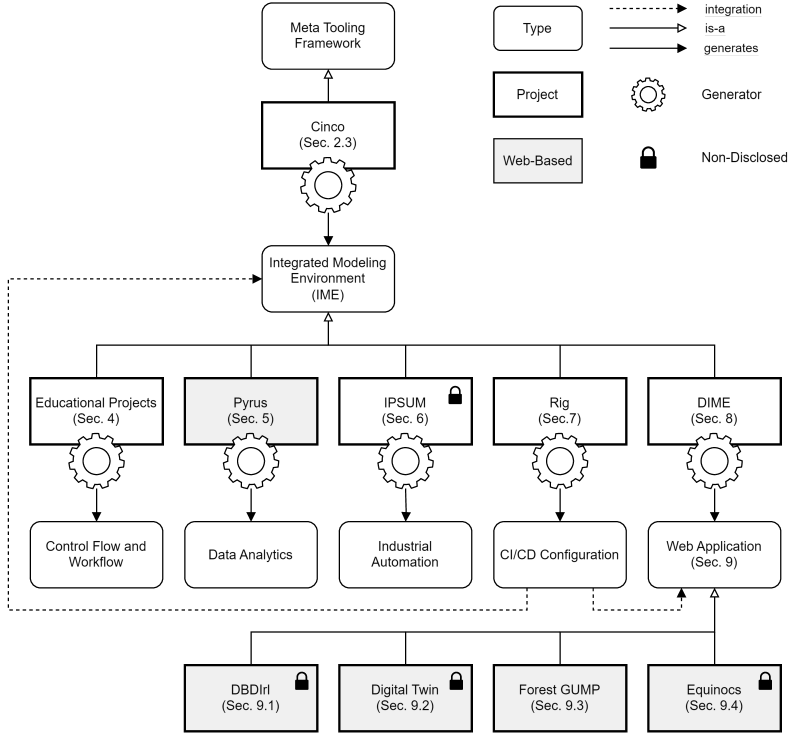
We illustrate the impact of LDE as a low-code paradigm with concrete implementations. All of them are fully automatically generated from models. Fig. 1 summarizes the structure and relationships of the considered tool landscape. In the figure, the fourth row shows typical Cinco products. These DSLs range from simple educational languages, explained in Sec. 4), via data analytics, industrial automation and CI/CD configuration, cf. Sec. 6 – Sec. 7, to the complex Dime application for developing browser-based applications in Sec. 8. The sixth row in the figure shows four products created with Dime. They are all browser-based applications, ranging from smaller academic products to Equinocs. The required CI/CD pipeline was automatically generated from models in the Rig. As indicated in the figure, almost all projects are open source. Interested readers can consult our website111https://scce.info and repositories on GitLab222https://gitlab.com/scce for more information and project insights.
Outline
The discussion in this paper is organized as shown in Fig. 1. Sec. 2 discusses the foundations of LDE and gives further background information. Sec. 3 describes related work. The conceptual background is provided by the three paradigms LDE, OTA, and Language-Oriented Programming (LOP) mentioned above, which are explained in more detail in the following section. We consider these three paradigms as the key to bringing the technology closer to the application experts by providing them with an interface that resembles their expertise and mindset. Sec. 4 – Sec. 8 then describe in detail concrete projects from different domains that were created with Cinco.
2. LDE Foundations
This section concerns mindsets, views, and experiences where the choice of notation made a difference: languages impose mindsets. Sec. 2.1 recapitulates the events that lead up to the LDE that we have today. Sec. 2.2 then describes the LDE fundamentals and the Sec. 2.3 explains the OTA key enabler.
2.1. History
We began to observe the tremendous impact of changing perspective from a computational how to a logic-based what. Often, supposedly critical problems fell apart after being reformulated in an appropriate way.
The next observation was that one has to speak the language of the people in a particular domain if one wants to convince them. Typically, we computer scientists think we can take the lead because we are the only ones who can “talk to computers”. The low-code approach tries to enable the application experts to participate in software development by drastically simplifying the coding. We consider such simplification alone as insufficient, because it does not necessarily reflect the mindset behind the application under consideration. If it is not done in a mindset-aware fashion, even low coding is still coding. We first experienced the power of this approach with the Service Logic Graphs (SLGs) we used in a project with Siemens/Nixdorf. In that project, part of the success was due to the formation of a successful mindset. Our industry partners began to use well-designed templates for temporal formulas to formulate critical requirements for their telecommunications infrastructure. At a second time, this change to the what perspective became particularly clear in the IPSUM project, which will be discussed in more detail in Sec. 6. The mindsets of the stakeholders were very different, but each of them expressed their views in their customary notation, e.g. in the form of a Piping and Instrumentation Diagram (P&ID), served to provide the alignment required for the OTA. Here, five domain-specific languages directly reflected the mindset of the industry partner.
Our first direct experience demonstrating the power of DSL-based mindsets came in 1991 with an attempt to prove the optimality of a partial redundancy elimination algorithm proposed by Morel and Renvoise (Morel and Renvoise, 1979). Instead of thinking in terms of fixpoint computations, as was common at the time, thinking in terms of temporal logic properties was a radical change in mindset. This led to shorter proofs and later allowed us to solve the two related problems of optimal reduction of register pressure (Knoop et al., 1992, 1993) and elimination of all partial redundancies (Steffen, 1996). The former solution is now the standard for optimizing compilers.
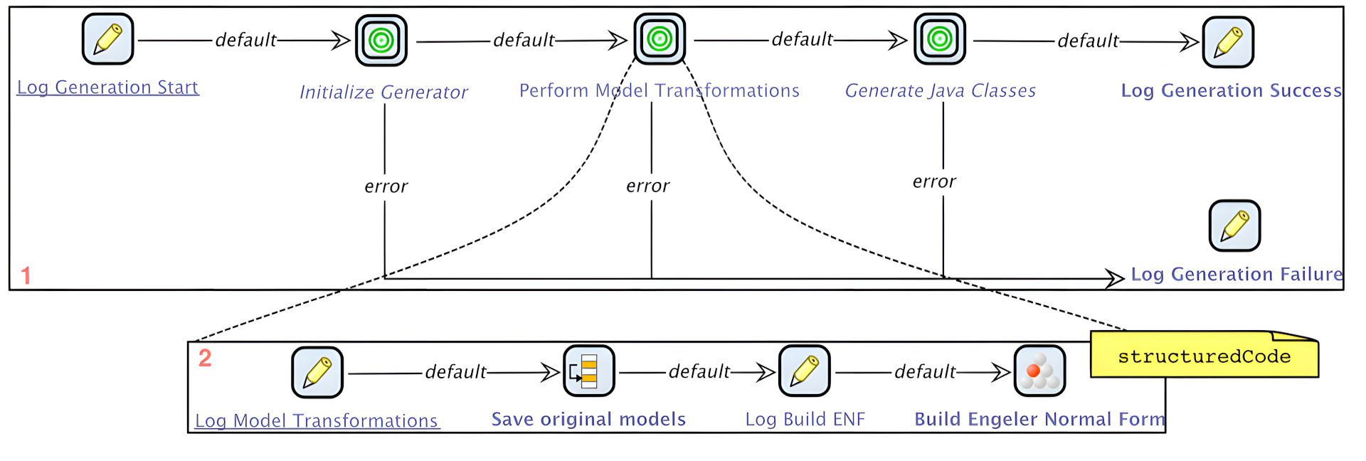
This mindset also gave rise to the idea of introducing code generators (Steffen, 1991, 1993) that could benefit from the considered domain. Full code generation became a central goal in all further developments. It was supported by a dedicated, graphical IME called Genesys (Jörges, 2011). Fig. 2 shows a Genesys-based code generator model. The idea of using reusable standalone components, later called Service-Independent Building Blocks in the ITU-T Standard (International Telecommunication Union, 1993), which can be easily recombined due to the simplicity of their interfaces, was motivated by the rapidly growing library of special commands for the Concurrency Workbench (Cleaveland et al., 1993). SIBs provided an adequate level of abstraction to introduce model checking and model synthesis (Steffen et al., 1993; Margaria et al., 2009).
This was the basis of the Electronic Tool Integration Platform (ETI) (Steffen et al., 1997a), which was later specialized to Bio-jETI (Lamprecht et al., 2011), a SIB-based graphical IME for modeling scientific workflows in bioinformatics. Bio-jETI was a service-oriented, low-code environment. Users could graphically model their workflows (processes), which could then be enacted without any programming.
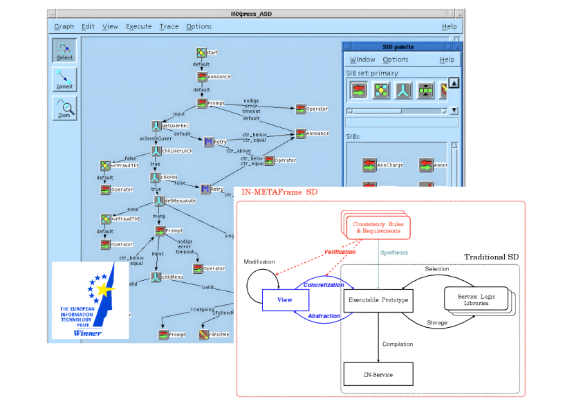
However, the greatest influence on our service-oriented development approach came from a successful industrial cooperation that resulted in the Siemens Nixdorf INXpress Service Definition Environment for Intelligent Networks (Steffen et al., 1996a, b) in the mid-1990s. The Service Definition Environment (SDE), based on the SIB concept combined with taxonomic classification and model checking, was evaluated to reduce the time to market by a factor of five and received an ITEA award in 1996. Fig. 3 shows a screenshot of the SDE and a conceptual diagram illustrating the underlying constraint-based approach. In retrospect, the SDE can be considered one of the first low-code environments. Telecommunication experts could graphically combine SIBs into Service Logic Graphs, which were continuously controlled by model checking. In fact, even we, the SDE developers, did not have access to the implementation code of the actual SIBs, which was considered proprietary. Our domain-specific modeling environment Dime for web-based applications, which will be discussed in detail in Sec. 8, can be seen as the sixth generation of our original SDE.
The simple service-oriented definition and exchange of functionality turned out to be a good way to communicate between the stakeholders (Margaria et al., 2005, 2006). All stakeholders were working on the same artifact, which we later called the one thing (Steffen and Narayan, 2007; Margaria and Steffen, 2009a) but at the appropriate level of abstraction that supported their mindset and was defined by the underlying service hierarchy. The underlying philosophy of full code generation was the basis for Java Application Building Center (jABC), a fully fledged low-code environment (Kubczak et al., 2009; Margaria and Steffen, 2009b). In addition, its model checking and model synthesis facilities provided dedicated support for controlling evolution at the logical, declarative level and for establishing product lines via their behavioral (temporal) properties (Jörges et al., 2012; Lamprecht et al., 2013). The latest version of jABC supports even higher-order services (Neubauer and Steffen, 2013; Neubauer et al., 2013).
The final enabling step for LDE was to move from DSLs defined by taxonomically organized service libraries to Cinco (Cinco), our framework for metamodel-based generation of graphical editors and full-featured IMEs (Naujokat et al., 2017; Naujokat, 2017). This step had two major impacts:
-
•
First, the move from jABC to Cinco’s web-IME Dime was a move from a process model with manual handling of data, GUI and deployment in jABC to an integrated modeling environment where dedicated environments for data, process, GUI, and CI/CD pipelines put these dimensions on equal grounds. These four DSLs provide purpose-specific views that allow the corresponding experts to model their part in their own mindsets. The first three DSLs are deeply integrated into Dime, meaning that the corresponding environment are part of the Dime IME. The integration of the DSL for CI/CD is shallow, meaning that Dime simply integrates the generated CI/CD pipeline, which will be illustrated further in Sec. 7. This move was only possible by basing our entire IME generation on Cinco because of the very different nature of the involved DSLs.
-
•
Second, the other projects listed in row four of Fig. 1 required the flexibility of Cinco-based IME generation. For example, this was needed to implement the token-driven PetriNet semantics, to enable data flow-driven execution semantics in Pyrus, and to enhance customer languages like P&ID and hardware diagrams in IPSUM.
2.2. Language-Driven Engineering
LDE addresses the need to provide low-code environments for the development of industrial-scale solutions, so that multiple stakeholders with different backgrounds and expertise can directly participate in the development process using Purpose-Specific Languages (PSLs) tailored to their specific mindsets. This means that interdisciplinary teamwork in an application domain typically requires multiple Purpose-Specific Languages to support the different needs of each team member. Thus, in contrast to DSLs (Steffen et al., 2019), PSLs are stakeholder-specific and tailored to achieve a particular goal; for example, in a development team, GUI designers, process engineers, quality assurance, and operations teams are supported by different PSLs.
PSLs are essential for efficient inter-stakeholder collaboration and communication, as they provide each team member with appropriate language support, as pointed out in Sec. 2.1. The key point of LDE is to consider language provision itself as a service. Adequately integrated PSLs can provide support at different levels, e.g.:
-
•
IME support, so that stakeholders can model the user-level functionality, which is then included in a service-oriented fashion, in a PSL. Examples of such PSLs are dedicated (graphical) query languages, languages for data analysis, e.g. as supported by Pyrus, as illustrated in Sec. 5, but also languages derived from graphical languages traditionally used in application domains, such as network layouts, workflow graphs, or P&ID, as shown in Sec. 6.
- •
- •
We also distinguish between deep and shallow language integration. This is a technically important distinction that tends to become fuzzy in the context of metamodel-driven language workbenches like Cinco.
-
•
In deep language integration, the special-purpose IME are integrated as a service into the global development IME. The data, process, and graphical user interface (GUI) language integration in Dime (see Sec. 8) are typical examples of deep integration.
-
•
Shallow language integration provides separate special-purpose IME that produce artifacts for the component library of the development IDE. In this case, the artifacts generated by the special purpose IME are integrated as a service. From the meta-level perspective, a PSL with an IME that is generated from any meta-model within the Cinco meta-tooling suite can be considered both as deeply integrated and as a special-purpose IDE resulting from the shallow integration of Cinco. For example, for an artifact that is itself an IME, in Pyrus we decided to do a shallow integration of the data PSL and simply provide a standard data model as a service. This decision lowered the entry barrier and led to higher acceptance by the users. In (rare) cases where the standard data model is not sufficient, one can use LDE to easily model and then (shallow) integrate an extended data model.
Whatever the perspective, the practical difference between shallow and deep integration provides a very powerful LDE discipline for tailoring IMEs (Steffen et al., 2019). Deep integration increases the conceptual complexity of the original PSL, while shallow integration provides additional external services to the users of the development PSL. For example, data analysis processes modeled with Pyrus.
2.3. The One Thing Approach
The key to successful LDE is the OTA. It combines the simplicity of waterfall development with maximum agility (Margaria and Steffen, 2009a) to ensure consistency. OTA is characterized by viewing the entire development process as a cooperative hierarchical, and interactive decision-making process organized by building and refining one comprehensive model, the One Thing. This approach allows each stakeholder, including the sponsor, the principal, and application experts, to make decisions in terms of constraints on an ongoing basis using their dedicated PSLs. Conceptually, each evolutionary step is viewed as a transformation or reification of this set of constraints, which typically comprises many modeling aspects and embodies multiple forms of knowledge. Dedicated PSLs and their associated views highlight open requirements and potential conflicts, and support goal-oriented and stakeholder-specific design decisions. A clear chain of command, authority, and responsibility assigns levels of priority to the stakeholder decisions according to their roles. This chain is organized to support intent-driven development. Typically, this means that the sponsor’s or the principal’s constraints have the highest priority and that the priority decreases as the level of technical detail increases.
LDE provides means to check for conflicts during the decision making process. The One Thing is the single source of truth and every other artifact is automatically generated from that source. This is a central point that prevents any form of round trip engineering. In fact, change requests can only be entered into the One Thing and by a person with the appropriate role. Any consequences for the lower levels are automatically enforced, i.e. communicated to corresponding stakeholders, via dedicated views (Jörges et al., 2012). The success of this approach is based on the interplay of the following three concepts:
-
•
Language-oriented decomposition that breaks down complex development tasks into specific subtasks, ideally handled by dedicated (domain) experts using a PSL. This decomposition works the better the closer the modeling language resembles (drawing) patterns that already have a tradition in the specific domain.
-
•
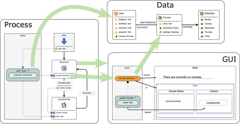
Global alignment through a global model, with simultaneous separation of concerns through specialized PSLs for each subtask. This holistic approach of bounded contexts can be seen as a solution for Domain-Driven Design (DDD) (Evans, 2003) where bounded contexts are a central aspect to minimize complexity while increasing flexibility, especially when each stakeholder can use PSLs specially designed for their needs. Considering the different PSLs for data, process and GUI modeling of Dime again, the incrementally growing data model that is built during system development is the backbone of the One Thing. Processes are defined in relation to this data model and also refer to each other. Each of the modeling editors involved provides the necessary views of the artifacts created by the other modeling editors. For example, the process model and the GUI model in Dime contain customized views of the data model (see more details in Fig. 12).
-
•
Constraint-based guidance, validation, and control manage complexity through automated assistance because the One Thing is multifaceted and hierarchical. For this reason, application constraints are formulated and continuously validated at the meta level, the development level, and at runtime. For example, our CI/CD pipeline, which seamlessly connects the meta-modeling level with the production level, automatically checks all constraints, ensuring that violating systems do not reach the production platform.
3. Related Work
Two properties are characteristic for LDE and its corresponding IMEs. First, LDE aims to enable all stakeholders to co-develop software without programming. Second, it explicitly supports multi-PSL–based collaboration of the individual stakeholders. The related work can be divided into approaches that address these two characteristics.
Languages for Non-Programmers
Fowler, who coined the term language workbenches (Fowler, 2005), characterizes the role of (textual) DSLs such that it is not that domain experts write the DSLs themselves, but that they can read them and thus understand what the system thinks it is doing (Fowler and Parsons, 2011). Low-code modeling approaches that rely on language workbenches, such as MetaEdit+ (MetaCase, 2024; Kelly and Tolvanen, 2008), the Eclipse Modeling Project (Gronback, 2008), Sirius (Sirius, [n. d.]), and (Web) GME (Ledeczi et al., 2001), explicitly address this mindset issue. They allow the language to be tailored to the skills and needs of the target domain experts. In addition, several graphical languages have become successful in dedicated application domains, such as MatLab/Simulink333https://www.mathworks.com/products/simulink, ladder diagrams (John and Tiegelkamp, 2010), and Modelica (Fritzson, 2004). Recently, large software companies have been pushing their low-code platforms, such as Google’s AppSheet444https://www.appsheet.com or Microsoft Power Apps555https://powerapps.microsoft.com. They provide a manually built development solution that resembles a spreadsheet-oriented mindset. The tradeoff between simplicity and generality is implicit: Simplicity is given whenever the spreadsheet-oriented mindset is appropriate. Other prominent examples, such as Mendix666https://www.mendix.com, Bubble777https://bubble.io, or Salesforce Lightning888https://www.salesforce.com/campaign/lightning, focus on (graphically) specifying workflows in a process model or flow graph style using manually programmed, application-specific activity blocks. These approaches address situations where a process-oriented combination of predefined building blocks is sufficient. This was the mindset behind the jABC (Steffen et al., 2007) before we started developing Cinco in an industrial project, which is the basis of the low-code approach presented in this article. Similar to the spreadsheet-oriented mindset, the adequacy of solutions depends heavily on a good fit between the mindset of the toolset and the application being addressed. The understanding that application experts should be addressed with graphical notations is also shared by the developers of the Kieler framework (Fuhrmann and von Hanxleden, 2010). They provide means to automatically generate domain-specific graphical views for textual DSLs realized in the Eclipse modeling context. While the kieler framework is indeed mature and powerful—so much that its layout engine is now generalized as the Eclipse project Eclipse Layout Kernel (ELK)999https://eclipse.dev/elk—its primary goal is to provide views to better communicate with non-programmers, while creating the actual (often textual) models still requires programmers or highly technically experienced domain experts. We therefore focus on graphical PSLs.
Prominent frameworks for graphical modeling language development include MetaEdit+ (Kelly et al., 1996), GME (Ledeczi et al., 2001), Marama (Grundy et al., 2013), Pounamu (Zhu et al., 2004), and DeVIL (Schmidt et al., 2008). These powerful frameworks are designed to generate graphical Integrated Development Environments for specified graphical DSLs including corresponding code generators. However, they do not address the aspect of coordinating stakeholders with different mindsets in a cooperative fashion. The same applies to the Eclipse101010https://eclipse.org modeling ecosystem (Gronback, 2008) with its Rich Client Platforms (McAffer et al., 2010) and Eclipse Modeling Framework (EMF) (Steinberg et al., 2008). Although there is extended support for textual DSLs in Eclipse, e.g. using the Xtext 111111https://eclipse.dev/Xtext framework, the creation of graphical DSLs, usually using frameworks such as GMF 121212https://eclipse.org/gmf-tooling or the Epsilon project (Kolovos et al., 2010), becomes tedious.
Lowcomote (Tisi et al., 2019) is a recently launched research project that explores current challenges in low-code development platforms. One of the goals of the project is to scale low-code approaches beyond simple Create Read Update Delete (CRUD) applications into domain-specific areas of interest, such as data science of Internet of Things (IoT). The project also aims to address the increasing fragmentation among low-code platforms with open standards and programming models that enable greater interoperability. Furthermore, the integration of heterogeneous models from different disciplines is an explicit goal of the project. Compared to our research, the Lowcomote project is relatively young, having only started in September 2019. We have been working on the vision of LDE for more than two decades, developing a comprehensive metamodeling framework for graphical PSLs, including model validation, full code generation, and language implementations for many domains. Nevertheless, there are interesting published results that are relevant to our research in the sense that domain-specific Model-Driven Engineering (MDE) has been applied to the IoT domain (Ihirwe et al., 2021). DevOpsML (Colantoni et al., 2020), also developed within the Lowcomote project, uses MDE for the purpose of modeling DevOps workflows. It attempts to capture the bigger picture of the complete DevOps workflow, including development, build, test, deployment, and operations. Software processes and DevOps platforms are modeled graphically, and then woven together using a link model that connects the requirements of the software process with the capabilities of the DevOps platforms. DevOpsML focuses on a higher level, without a clear distinction between DevOps and CI/CD. Rig considers CI/CD as the central building block of DevOps and provides a graphical PSL as a comprehensive and self-contained approach that can be integrated in a shallow way into any DevOps process. It has been successfully integrated in industrial projects, such as Springer’s Equinocs, and generates complete CI/CD pipelines.
The modeling language CHESSIoT for IoT systems was developed on top of the CHESS tool (Debiasi. et al., 2021) to improve the safety of IoT systems and to facilitate validation through model checking. It provides metamodels for system, software, hardware, and operational aspects. As model checking and validation are widely applied in our LDE research, our goals are similar in this regard. While our research is focused on PSLs, CHESSIoT is dedicated to the entire industrial IoT domain without further specialization for a specific purpose. In addition, full code generation is an essential part of the LDE process, whereas CHESSIoT is targeting the ThingML (Harrand et al., 2016) modeling language, which has not yet been implemented.
In the area of model-driven web application development, Bozzon et al. (Bozzon et al., 2008) explore how model-driven approaches can support the transition to Web 2.0. They use models to capture important social and technological aspects of this transition. The beContent project (Cicchetti et al., 2009) defines a programming system where graphical models and textual programming of a web application are synchronized in a round-tripping process. In contrast, Dime eliminates the round-tripping process by implementing full code generation.
Language-Driven Development
The Racket team’s (Felleisen et al., 2018) LOP approach is aligned with LDE in terms of explicit support for multi-DSL. In fact, LOP advocates multiple cooperating languages for a project, has a feature called Foreign-Function Interface (FFI) (Foreign-Function Interface) similar to our notion of native services, and uses a meta-language syntax parser to define languages. However, there are clear conceptual differences that limit cooperation with non-programmers. LOP relies on internal DSLs, called embedded Domain-specific Languages, based on the single base language Racket131313https://racket-lang.org, which is a successor to Lisp (Weissman, 1967). Discouragingly, even exemplary eDSL code must be annotated with simple graphical notations for readability to communicate with non-programmers. (Andersen et al., 2017)
Another prominent approach to model-driven development is projectional editing (Völter et al., 2014), such as provided by JetBrains’ Meta Programming System (MPS)141414https://www.jetbrains.com/mps. This approach is mainly aimed at programmers who are proficient in different (programming) languages. PSLs relate to projectional editors, the one thing to abstract syntax tree (AST), and our constraints to the wealth of constraints that can be imposed on ASTs. The difference is that LDE is technologically free-style due to Cinco s service-oriented fashion, as long as consistency is maintained. This means that an adequate extension of a technology usually also imposes the need for a PSL that defines the corresponding consistency constraints. For example, adding model checking to the Dime landscape required a PSL for transforming Dime models into verifiable models that can be realized using the transformation approach. (Kopetzki et al., 2021a)
The ROCCO tool (Rani et al., 2020) has similar goals. It makes graphical modeling languages based on Eclipse EuGENia151515https://www.eclipse.org/epsilon/doc/eugenia accessible in a web-based low-code development platform. ROCCO performs the migration by generating diagram models for evaluation in the Psi Engine (Chavarriaga et al., 2017), a web-based low-code environment. Compared to Pyro, ROCCO does not provide collaborative editing of the diagram models.
4. Educational Projects
Cinco provides students with a tangible experience with formal modeling. The following subsections present two prominent examples, first, a PSL for classical control structures in Sec. 4.1, and second an intuitive tool for simple point-and-click games in Sec. 4.2.
4.1. Classical Control Structures
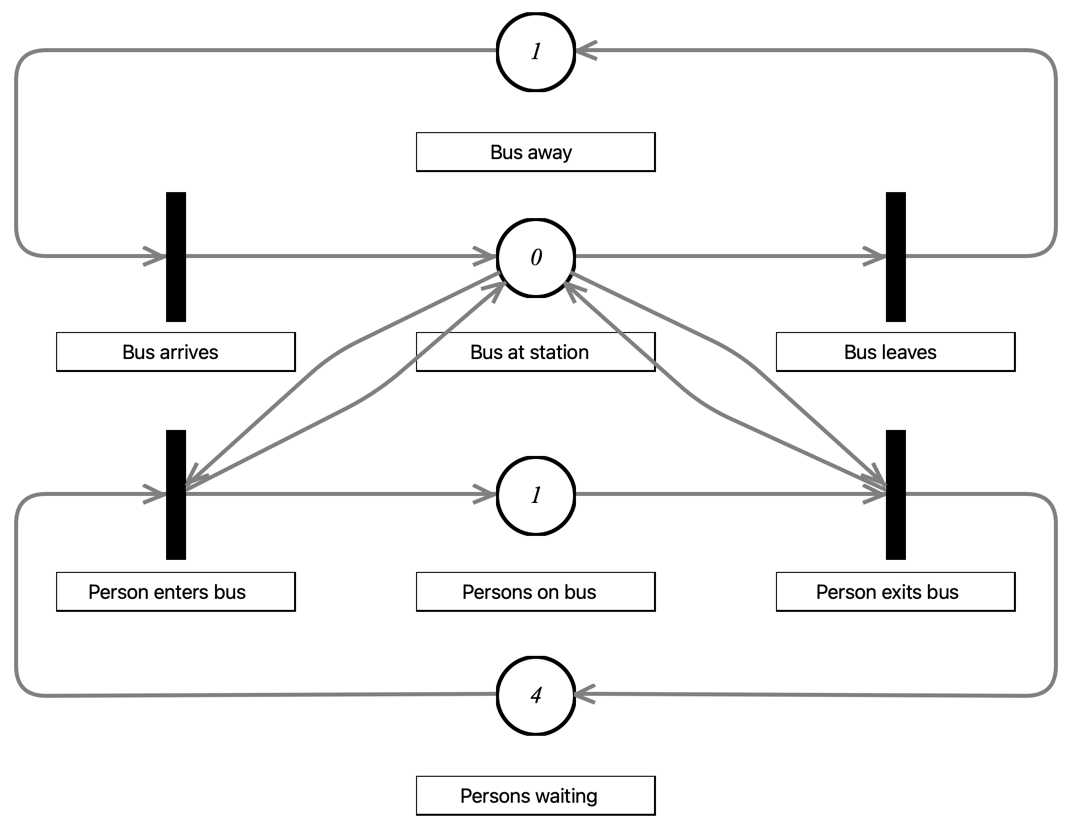
A variety of diagram types are commonly used in software development and computer science. There are tools for modeling complex systems and visualizing processes, behaviors, and interactions. Their graphical nature makes them a natural use case for graphical PSLs and therefore reasonable examples for Cinco products. The following two figures show two examples of models modeled with a tool generated with Cinco. First, a Petri Net in Fig. 4, and second a statechart in Fig. 5. These projects automatically provide the corresponding editors and checkers and may be used to teach how to use these specific diagram types. They provide a responsive hands-on experience, including model validation and the ability to run simulations. Furthermore, they also demonstrate core features of Cinco and how to implement them. Hence, Cinco product developers can use them as reference implementations for creating their own PSLs.
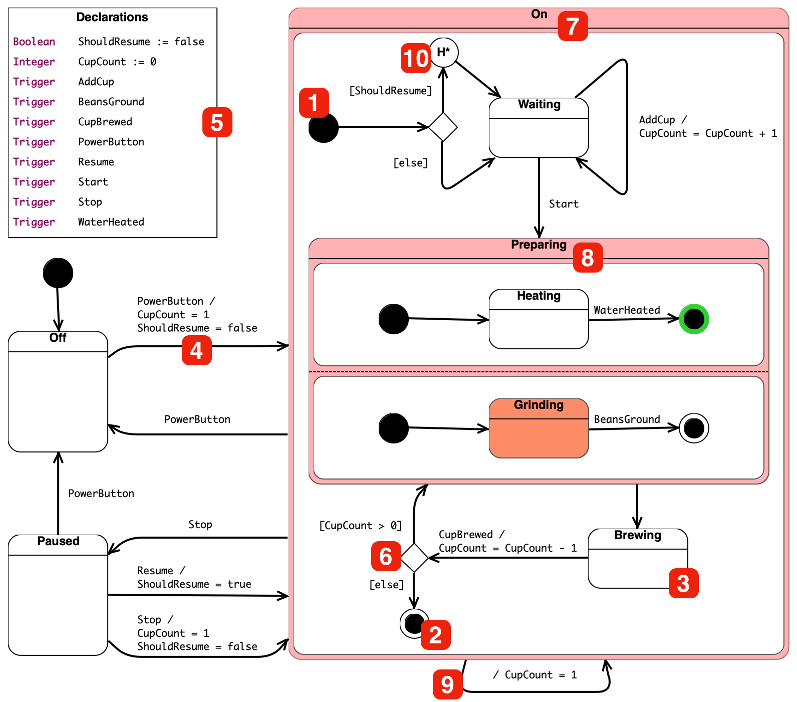
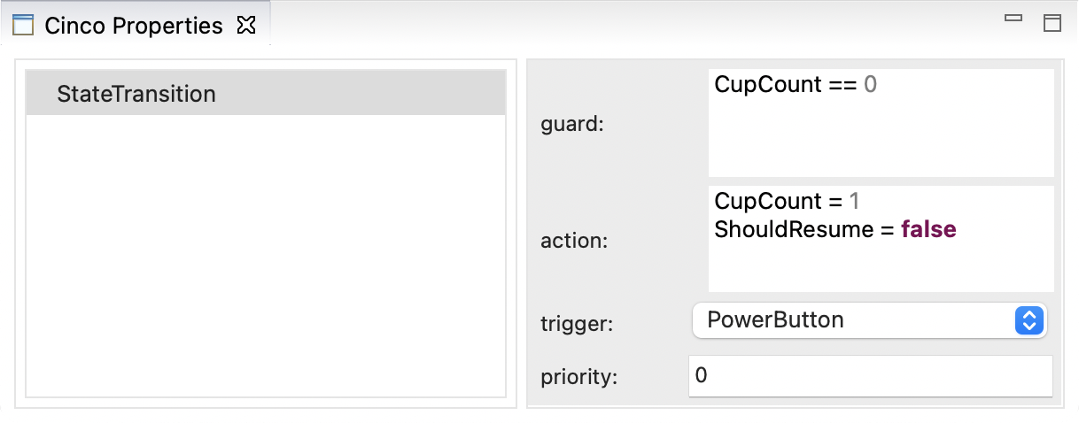
Focusing on the statechart in 5(a), which allows the creation and simulation of finite-state machines, the corresponding PSL comprises a subset of the Unified Modeling Language (UML) state machine specification. Basic model elements, such as start (1), end (2), and state (3) nodes, as well as transitions, (4) are available. Variables, which can be boolean or integer, and triggers are defined in the declarations container (5). During simulation, their current values are displayed in a table view. Triggers symbolize external events or inputs to the modeled system. They can be activated using buttons in the simulation interface. The properties of transitions, shown as an example in 5(b), define if and when a transition can be activated. They can refer to both variables and triggers. If a transition’s source node is active (highlighted in orange), its guard expression evaluates to true, and the trigger is activated, then the transition becomes active and its action is executed. Afterwards, the target node of the transition becomes active. The guard and action text fields are each editor views, that use textual DSLs powered by Xtext (Efftinge et al., 2012) for boolean expressions and variable assignments. They support syntax highlighting, syntax validation, and code completion. In addition to these basic elements, there are also a stateless decision nodes (6) that use guard expressions to branch the control flows.
Statecharts also include rather powerful concepts, such as hierarchical (7) and concurrent (8) states. Hierarchical states allow the user to group several states together. When the end node inside a nested state is activated, the default transition—that is, the only transition without an assigned trigger (9)—is activated. The execution of a nested state can be interrupted by using an outgoing transition with an assigned trigger. For example, triggering a Stop in 5(a) will always transition from the On state to the Paused state. All internal states are deactivated. However, the last active states are saved by a history node (10) (if present). Activating such a node will restore the last active states.
The aforementioned concurrent states (8) are a special case of the hierarchical states. Their two or more regions are states that are executed concurrently. Like the nested states, they can be interrupted and use history nodes to restore their active states. The difference is that each region’s end node must be active in order to activate the outgoing default transition. The Preparing state in 5(a) has two regions. The first one is finished, as its end node is already active (green). The second region is not yet finished, because the coffee beans are still being ground.
4.2. The WebStory Language
The WebStory language (Lybecait et al., 2018) is a simple example for Cinco. It is a graphical PSL for easy authoring of basic Point&Click adventure games, and comes with a modeling tool to assist users creating such games. Modeled WebStories are generated into source code based on web technologies, so the games are fully functional websites that can be executed by a browser. Following the storyboard concept, a WebStory basically describes the flow from one screen to the next. Each screen primarily displays a background image and contains one or more clickable areas. When playing the game, the player moves from one screen to another by clicking on certain areas of the image to reach a predefined goal. Between screens, a trigger can change the state of the game, e.g., picking up a key. Target screens may be unreachable until the game is in a certain state, e.g., when the correct key has been picked up.
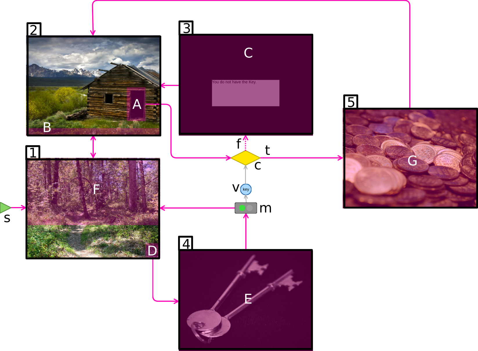
footnote 17 shows an example WebStory where the goal of the players is to find a treasure. The treasure can only be obtained if the player finds the required key. The WebStory uses several language elements alongside the basic screens 1-5. The click areas A-G connect two screens by purple directed control flow edges. The start marker s defines the entry point for the player. Triggers serve as variable modifiers m. The boolean variable v marks the possession of the key, which is then tested by the condition c. Conditions and variable modifiers are connected to variables by grey data edges. The values of all variables define the state of the game. In this example, the key variable holds the information whether the player has the key or not. The value of the key variable is potentially changed by the variable modifiers and evaluated by the condition. A true edge t links to the treasure screen if the key was found before. Otherwise, the false edge f displays a message with the information that the key has not yet been found.
We use the WebStory language and its variants for teaching purposes. This is complemented by another PSL for language-to-language transformation, which is similar to the idea of Structural Operational Semantics (SOS) in a graphical fashion. In (Kopetzki et al., 2021b) we have shown how to use this language to define the transformation that implements a preprocessing for model checking, i.e to derive a Kripke Transition System (Müller-Olm et al., 1999) that belongs to a given WebStory.
5. Pyrus: Low-Code Data Analytics
Scientific workflow modeling tools such as ETI (Margaria et al., 2008), Taverna (Li et al., 2008), or Kepler (Altintas et al., 2004) have been developed to enable the composition of data analysis web services. Web services must first be declared in a central repository in order to be integrated into the graphical modeling environment. The execution of the created workflows is done through a step-by-step traversal and Remote Procedure Calls (Nelson, 1981) to invoke the services. While this approach has been successfully applied to various scenarios, such as Bioinformatics (Lamprecht, 2013) and workflow management (Migliorini et al., 2011), it has two major drawbacks. First, the central repository requires a lot of manual effort to synchronize and maintain. Second, execution via RPCs results in large data transfers for each service deployed.
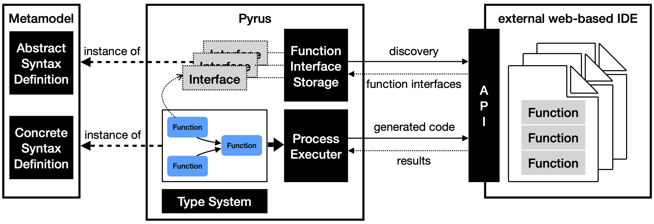
The Pyrus tool181818https://gitlab.com/scce/ml-process follows an alternative approach by directly integrating the functionality implemented in an external online IDE, such as CodeAnywhere (Añel et al., 2020), Jupyter (Beg et al., 2021), or Amazon Web Services (AWS) Cloud 9 (Amazon Web Services, Inc., 2023), instead of instrumenting services via a repository. The concept is illustrated in Fig. 7. Pyrus discovers existing functions and enables graphical composition in a data-driven process modeling. The process PSL was created using the Cinco specification languages and then generated in a collaborative web-based environment using Pyro, an alternative generator to Cinco that generates IMEs that run as web applications in browsers. This allows domain experts and programmers to work together simultaneously and benefit from each other.
The created processes are fully compiled and delegated to the external IDE runtime environment for execution. This concept is consistent with the LDE approach (Steffen et al., 2019) of incremental transformation followed by service-oriented execution. In this way, only the code, input data and results need to be transferred, allowing for more efficient execution.
In the following subsections, we illustrate the modeling environment in Sec. 5.1 and the discovery of data analysis functions in Sec. 5.2. Then, Sec. 5.3 illustrates the execution of the modeled processes.
5.1. Modeling Environment
The Pyrus modeling environment enables users to create data-driven processes online by composing previously discovered functions of, for example, Jupyter. The editor, shown in Fig. 8, provides a process creation canvas in the center and various widgets for validation (1), element creation (2), and project management (3).
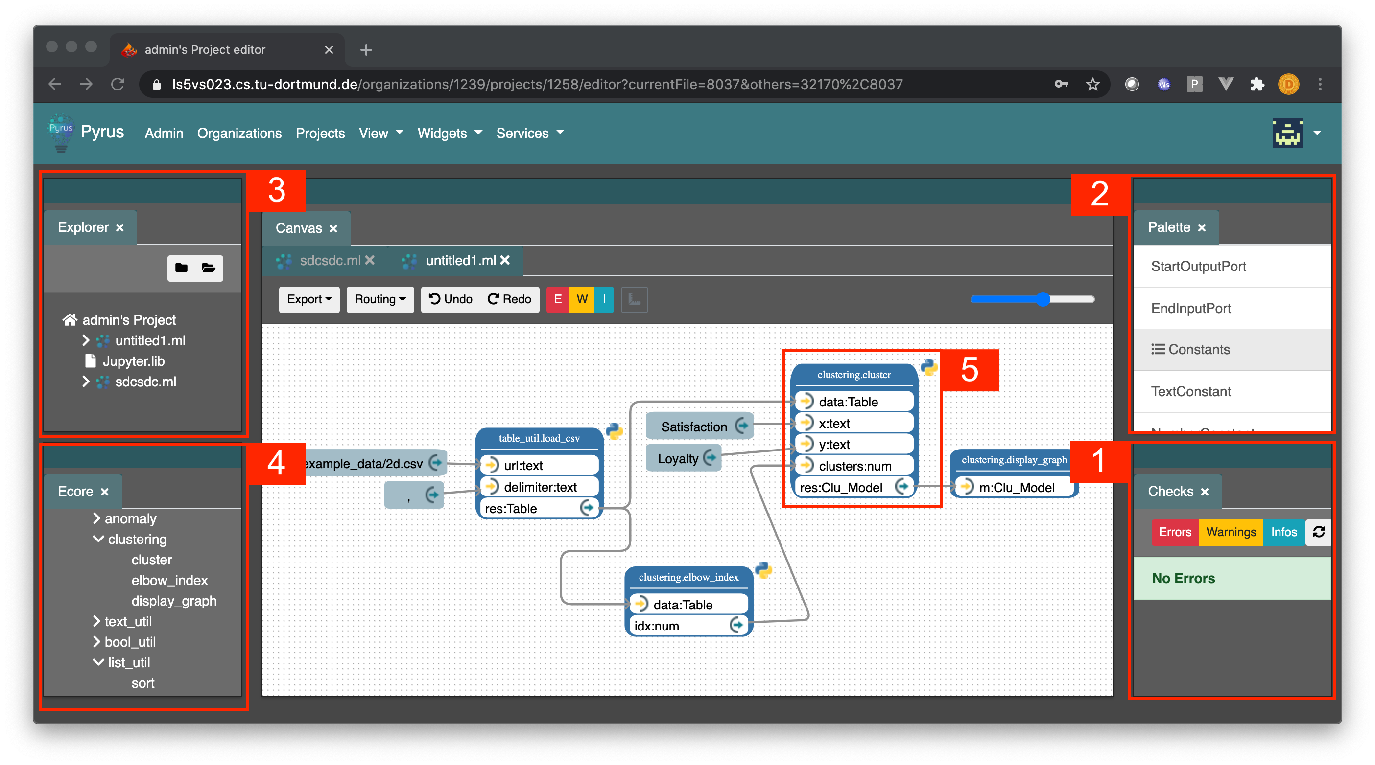
The data process PSL of Pyrus allows the acyclic composition of external functions by adding a reference from a function container to a function interface. The function interface storage represents the functions present in the connected IDE. In Jupyter, for example, these functions are implemented in Python. All recognized functions are displayed in the modeling environment in an ordered and grouped way (4). Each function container is assigned input and output ports according to the available parameters and the output of the referenced function interface (5).
As shown in the example process in Fig. 8, ports are connected by directed edges, which describe the data flow within a process. After each user edit, the environment checks whether connected ports are of the same nominal type using a type inference mechanism related to Milner’s (ML) language (Harper et al., 1986).
To reuse created processes within the environment, Pyrus is capable to structure process models hierarchically. For this purpose, a hierarchical process can be represented by a single node containing the corresponding ports of the underlying model.
5.2. Function Discovery
In contrast to the service repositories, Pyrus allows the direct use of online implemented functions. The Jupyter online IDE, is one of the most used and established programming environments in the area of data analysis (Perkel, 2018). It already contains a large number of functions for this service, which can be reused at will. The Application Programming Interface (API) of the online IDE is instrumented to detect which functions are available in the current project. First, all files are analyzed to detect whether they have a function signature annotation. Such an annotation can be programming language independent to support different languages.
In order for Pyrus to recognize a function, its signature must be declared. This includes the actual function call, the required input parameters and the output to be returned. As shown in 1, this signature description is specified as comments before the actual implementation of the function. Each parameter is specified by a tuple of a name and a symbolic type. At this point, all functions annotated this way are discoverable, characterized, and can be used within the Pyrus modeling environment.
5.3. Process Execution
The execution of the modeled processes in Pyrus is done by delegating fully generated code to the host IDE to instrument its runtime environment. Fig. 9 shows this instrumentation. First, the data-driven processes are transformed into a control-flow process, also specified with Cinco. Thanks to the transformation APIs (Lybecait, 2019) that Cinco generates for every PSL, the translation of the models is automatically supported on the framework side. It is based on a topological sorting of function and sub-process containers according to their preceding nodes.
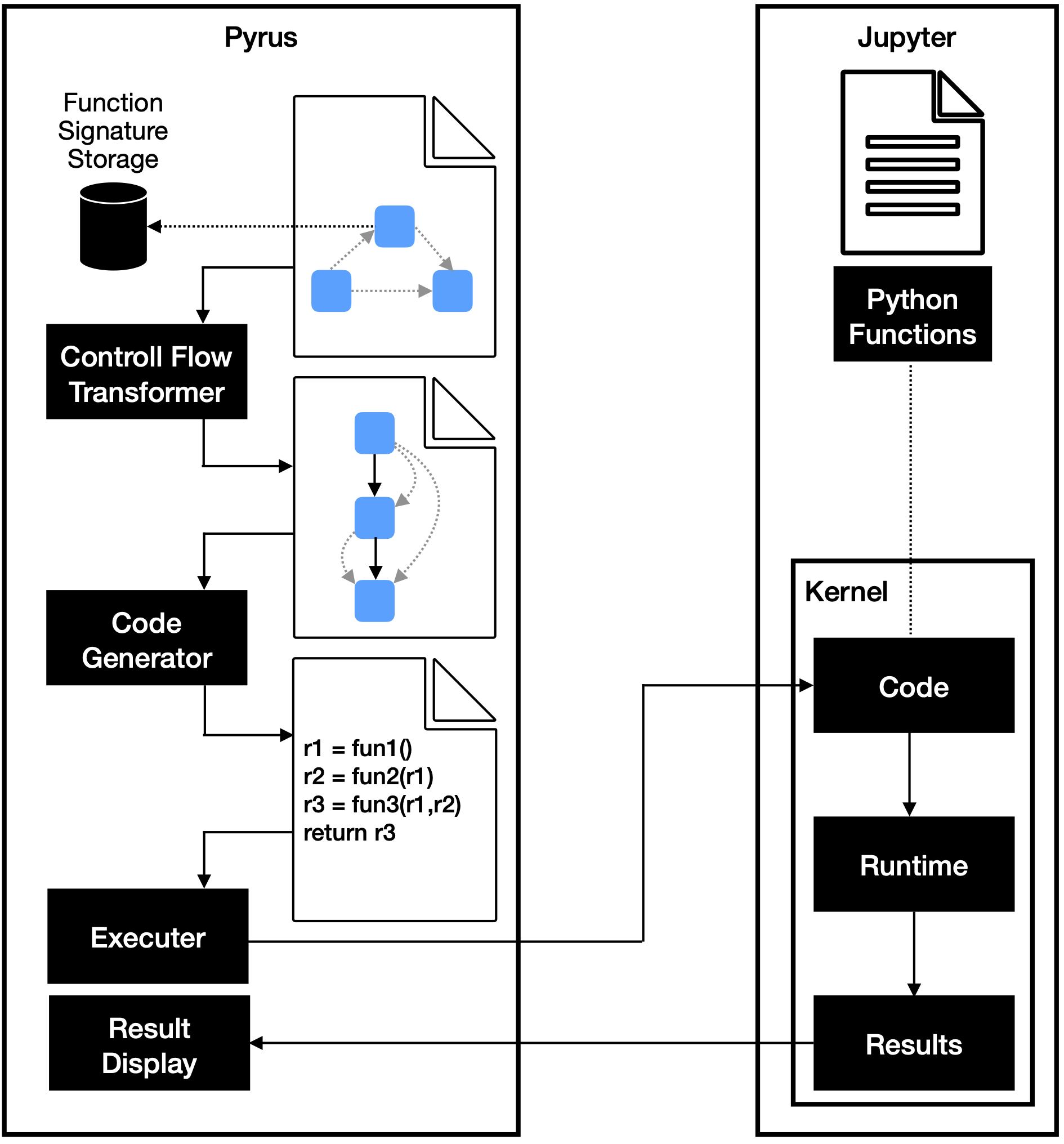
Second, once the control flow process is created, the associated generator is used to generate Python code. The generated code reflects the process hierarchy and instruments the functions within the Jupyter IDE. Third, the complete code is passed to the runtime environment via the IDEs API and executed. The results are transferred back to Pyrus and displayed to the user in the Web GUI environment.
6. IPSUM: Low-Code Industrial Automation
In a cooperation project with GEA Group AG (Goldap et al., 2017), we have developed a Cinco product for the planning and programming of plants for industrial processes involving separators and decanters, i.e. industrial centrifuges. Such processes are found, for example, in the food, pharmaceutical, and oil and gas industries. The development of such an industrial process involves experts from several disciplines, such as mechanical and electrical engineering, process chemistry, and Programmable Logic Controller (PLC) programming, who must work closely together, but usually without a clear common communication channel; especially one that successfully bridges the gaps between these disciplines.
The traditional engineering workflow starts with a process technician working with the customer to develop a solution. The process technician then typically designs a P&ID according to International Organisation for Standardization (ISO) 10628-1:2015, a common diagram used in the process industry to show piping and material flow between components (International Organization for Standardization, 2014). Flow graph diagrams are also often used to illustrate this specific process. Typically, these diagrams follow a company’s internal norms or standards, which are often only implicitly defined by the combined knowledge and habits of experts in different fields. After the design phase, the process technician then passes the diagrams to a programmer to implement the specifications on a PLC or Industrial PC (IPC). However, because there are no real formally specified standards, this software development methodology results in a significant gap in specification and, potentially, understanding. This requires extensive testing and multiple time-consuming and error-prone communication cycles between process technicians and programmers.
A common approach to solving this collaboration problem is to standardize the process development, and in particular the software design, by establishing standard workflows, notations, models, and more. However, this usually falls short of the desired goal, as developers start to bend these standards to their individual needs. In contrast, an LDE approach to this issue involves standardized models in a highly specialized tool. Such a tool establishes Archimedean Points (Steffen and Naujokat, 2016), which are immutable aspects of the domain it specializes in, so that developers are automatically guided and constrained by the built-in standards.
The main goal of our cooperation project with GEA was to provide process technicians with such a highly specialized modeling tool to consistently specify the layout of the plant down to its actual functionality. This consistent specification is the basis for the fully automated generation of the complete executable program for the PLC or IPC. IPSUM (Industrial Process Software Utilizing Modelization), our proof-of-concept implementation, runs on a Beckhoff Industrial PC but other architectures, such as the Siemens S7, are also feasible. Following a core concern of the LDE paradigm, the system builds directly on the notations, formalisms, and workflows already in place at GEA to minimize the required training phase.
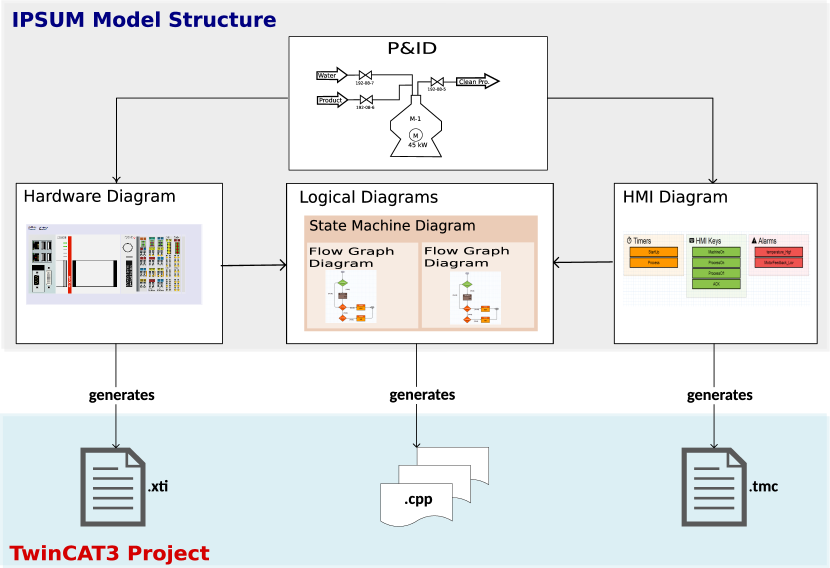
The resulting Cinco-based low-code environment consists of five interconnected graphical modeling languages used to describe different aspects of the system. Fig. 10 shows an overview of these diagram types and how they influence each other. At the top is the Piping and Instrumentation Diagram (P&ID), which follows the ISO standard notation for defining the physical layout of the plant, including pipes, valves, motors, pumps, metering, points, etc., and serves as the starting point for the process technician. A Hardware Diagram defines the layout of the physical components within the control cabinet, i.e., the PLC or IPC and associated hardware I/O components. Logical Diagrams define the programmatic behavior of the plant. We support hierarchical modeling of two types of logical diagrams, namely state machine and flow graph diagrams. State Machine Diagrams are used to define the abstract high-level behavior of the plant with states that are executed in each control cycle until a guard condition transitions to another state. Within state machines, flow graph diagrams model low-level functionality, such as reading and writing variables and making decisions based on their values. The state machine layer also handles cyclic execution, since control programs are typically executed periodically, such as every 20ms. They can also be inserted as action components in other flow graphs to build hierarchical structures. Finally, an HMI Diagram defines additional data structures that are primarily used within the user interface, such as alarms, warnings, timers, and parameters.
The one thing model structure is then transformed by the code generator into a fully functional Beckhoff TwinCAT 3 project, generating three types of files:
-
•
.xti describes the entire hardware and is therefore the interface to the I/O ports. IPSUM currently supports the hardware with the EtherCAT protocol, which is widespread among Beckhoff’s customers.
-
•
.tmc defines the interface to the HMI.
-
•
.cpp contains the program logic and is embedded in the given architecture of the Beckhoff TwinCAT3 Cycle IO project.
The IPSUM tool was successfully evaluated on a Beckhoff Embedded PC with simulated inputs and outputs. We have shown that the LDE approach, with its built-in standardization of the workflow and formalization of models, can indeed achieve fully automated generation of the PLC software widely used in industrial automation.
7. Rig: Low-Code CI/CD Modeling
In this section, we introduce our model-driven approach to continuous practices and present Rig191919https://gitlab.com/scce/rig, our visual authoring tool for CI/CD pipelines (Teumert, 2021). Rig is a Cinco product, as shown in Fig. 1, and is therefore an Eclipse RCP Application. It comes with an integrated code generator and is able to derive correct configuration files from the given workflow model. As a result, it reduces the need for developers to become familiar with the intricacies of YAML Ain’t Markup Language (YAML) and the concrete structure of CI/CD configuration files.
CI/CD pipelines are used to continuously build, test, and deploy the target application. This is often done with each push to a version controlled source code repository. A unit or step in this configuration is called a job. A job consists of a script, commonly sh, and associated information, such as infrastructure. Jobs in a CI/CD pipeline form a directed acyclic graph (DAG). If they are independent, they can be executed in parallel, whereas jobs that are dependent on each other must pass artifacts and related information back and forth in order to proceed. Job definition reuse is often limited. In practice, textual duplication is a common solution. Applications built for multiple target platforms, e.g., Windows, Linux, and MacOS, often require duplication of these jobs with only slightly different configurations, e.g., regarding infrastructure. Some platforms, such as GitLab, have introduced job templates to facilitate job reuse. CI/CD configurations are typically specified in YAML. While YAML is an adequate data serialization language that is intended to be human-readable 202020YAML Specification Version 1.2 https://yaml.org/spec/1.2/spec.html, practice shows that writing correct configurations remains an error-prone task (Tegeler et al., 2019).
Rig provides a model that uses jobs, script arguments, build targets, and parameters. Targets are a newly introduced concept that provides freely configurable parameters that are used to parameterize jobs. These parameters are used to provide the values for script arguments, allowing jobs to be customized for different build targets. This mechanism greatly simplifies job definition reuse and provides a powerful visual alternative to template-based approaches. Because workflows are modeled as DAGs, a correct order can be derived from the model, allowing stage assignments to be set automatically. In addition, the developer does not need to maintain dependencies between jobs because they can be automatically derived from the model. The Rig PSL extends this model by introducing properties and variables as well as configuration nodes. Jobs and configuration nodes have properties. Script arguments are simply a special type of property with a configurable name and variables are model elements that provide literal values. Both, variables and parameters from build targets provide values for properties, extending the customization possible with parameters. Using targets reduces the number of jobs that must be maintained and written because the concrete instances of jobs for each target are automatically derived during code generation. This helps reduce errors because a change in one job does not need to be repeated for multiple targets. Similarly, variables can be used to keep values synchronized between jobs.
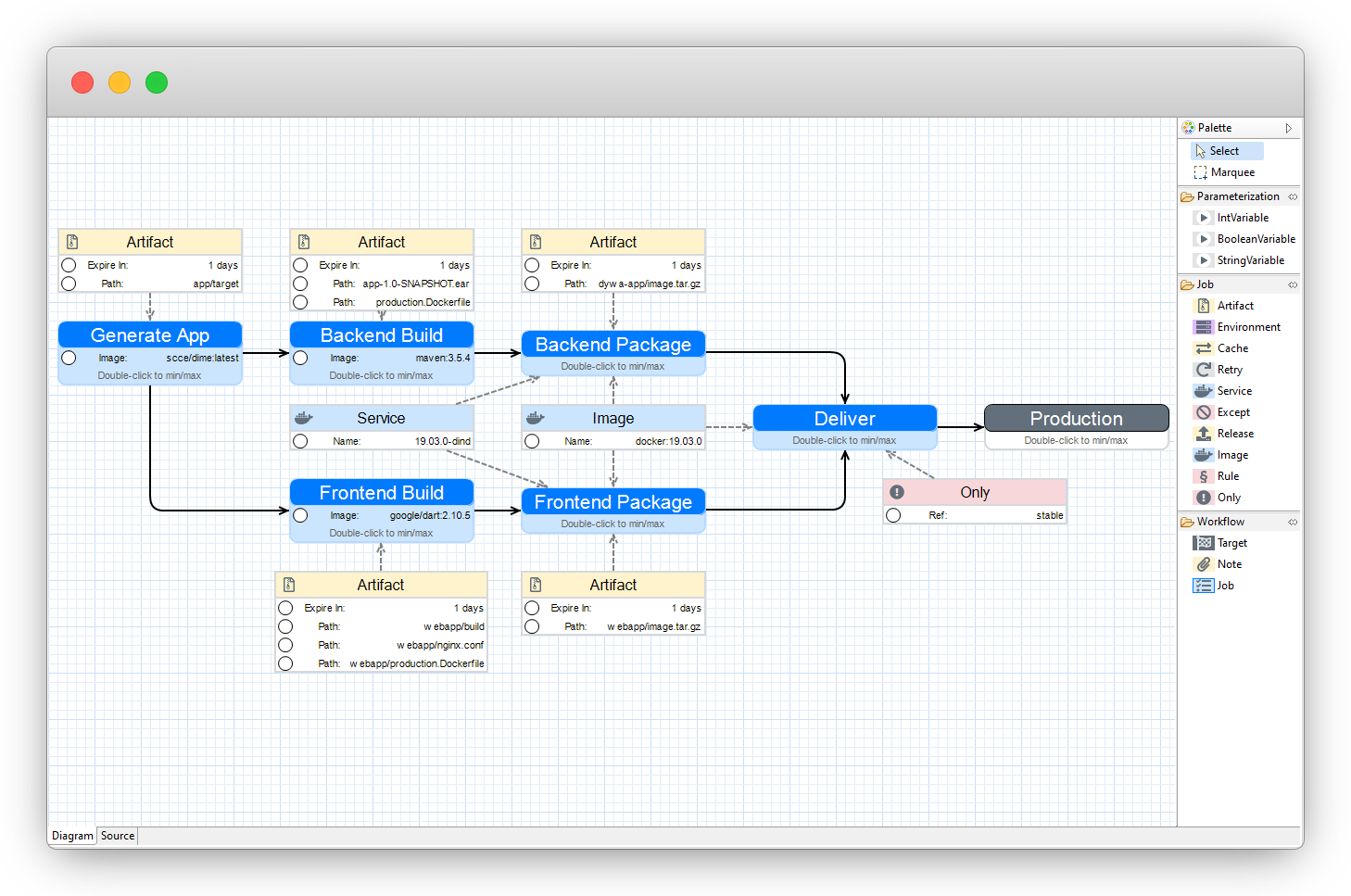
Fig. 11 shows the CI/CD workflow for Dime applications, which will be discussed in more detail in Sec. 9, as an example for a Rig model. The modeled workflow automatically transforms graphical models created by Dime into executable web applications. The workflow runs from left to right. It starts with Generate App, a job that uses Dime to load the graphical models and generate the source code of frontend and backend as well as some infrastructure as code, e.g. Dockerfiles. Using the resulting source code, Frontend Build and Backend Build resolve dependencies, such as libraries, and compile the source code into executable artifacts. Next, Frontend Package and Backend Package create container images, i.e. Docker images, which receive the runtime environment for the executable artifacts from the previous stages. Finally, the workflow ends with the Deliver job, which delivers the container images to a container registry, from which these images can be deployed to production.
8. Dime: Low-Code Application Development
Dime 212121https://gitlab.com/scce/dime is an IME designed for straightforward modeling and full generation of web applications (Boßelmann et al., 2016). It provides both graphical and textual modeling languages as well as several editors and views specifically designed to support recurring modeling steps. The following subsections cover various aspects of Dime. Sec. 8.1 gives an overview of the PSLs involved in Dime. A short description of the modeling environments is given in Sec. 8.2. Finally, Sec. 8.3 covers the consequent automatic generation of the complete web application stack along with the corresponding CI/CD-related artifacts.
8.1. Application Modeling
Strictly stated, Dime is a Cinco product. For application modeling, it provides both graphical PSLs developed with Cinco and textual PSLs developed with the Xtext framework. Thus, each model type in Dime is based on a well-defined metamodel. The graphical languages rely on graph model structures with nodes and edges as their basic components as well as containers, which are nodes that can contain other nodes. The textual languages use various features known from text editors in modern IDEs, such as syntax highlighting, code completion, and scoped linking of objects. Both language types, graphical and textual, come with a semantic model validation that guides the user through the creation of sound models.
Consistent with LDE, the languages in Dime are purpose-specific. They are intended to define specific parts of a central model that represents the one thing, in this case the web application. From a formal point of view, the different languages come with different metamodels and therefore the models defined with these languages are heterogeneous. Each of them allows one to reference other models or model elements defined elsewhere in a consistent way. Such cross-model references are first-class citizens in Dime. This mechanism leverages model-level reuse and naturally encourages the modeler to build a set of models that are tightly coupled.
Data Models
Developers create graphical models of the application domain from data types with specific attributes using Data Models in Dime. The relationships between data types are modeled with different edge types to express the type hierarchy and uni- and bi-directional associations. The attributes of a data type can be of primitive or complex types. Available primitive types are Text, Integer, Real, Boolean, Timestamp, and File. Complex attributes correspond to modeled associations between data types. Attributes can be modeled to hold a single value or a list of values, regardless of the actual type. There are two kinds of special types. The Enum type holds a fixed set of literals and a special User type holds user data, such as the user’s first and last name, and user credentials, such as the user name and password for logging in. Different Data Models of different Dime projects can share the same User type to express that the respective web applications have the same user base. The Data Model in Fig. 12 shows a small example that includes a User and the Enum type. The figure also shows how dependencies that span multiple models of different model types are represented and handled accordingly.
The data types and attributes of Data Models serve two main purposes. On the one hand, they provide the basis for all data flow-related aspects in Dime’s other modeling languages, such as the type of input and output of modeling components. On the other hand, Data Models define the structure of data objects at application runtime, thus defining the requirements for the persistence layer of the application.
Process Models
The business logic of the intended application is also created using graphical models, called Process Models. According to typical business logic implementations, they combine control flow aspects and data flow aspects.
Control Flow
The control flow of Process Models is defined by directed control flow edges connecting basic components called Service-Independent Building Blocks (SIBs). SIBs are reusable modeling components that represent an arbitrary kind of executable service. The control flow within Process Models defines an execution order of services. The Start and End SIBs are special built-in SIBs that define the single start and one or more end points of a process. The control flow in between can include any number of SIBs. In this way, a Process Model defines an executable service with its Start SIB as the entry point and its End SIBs as possible outcomes.
While so-called Native SIBs directly reference a specific service implementation, there are other types of SIBs that reference existing models or model elements from the current workspace. The most prominent of these are Process SIBs and GUI SIBs, which reference Process Models and GUI Models, respectively. Thus, these SIB types enable model reuse and, in particular, the creation of hierarchical model structures. (Steffen et al., 1997b)
In addition to the Data Model, Fig. 12 shows a Process Model that references two submodels. It contains a GUI SIB labeled Overview and a Process SIB labeled Unsubscribe. As components of process models, SIBs consist of a main node representing the actual service and several branches, depicted as outgoing edges, representing different outcomes of the service call. In terms of Native SIBs, these outcomes correspond to the possible results of a method call, which is essentially either its successful execution with an optional return value, or an error caused by some kind of exception. In terms of Process SIBs, the outgoing branches correspond to the End SIBs of the referenced Process to represent different outcomes of process execution.
Data Flow
The data flow of Process Models is defined by directed data flow edges between ports of variables in so-called data contexts. All ports are typed, either by specifying one of the built-in primitive types or by referencing a data type defined in a Data Model. The SIBs in Process Models can have input ports, while their branches can have output ports. Input ports express that data objects can be provided as arguments to the represented service. In turn, an output port on a branch expresses that data objects will be returned from the service when its execution is completed. Since different process outcomes can produce different outputs, it makes sense to locate the output ports not on the service, but on the specific edges associated with the respective outcomes.
To define the inputs and outputs of Process Models themselves, their Start SIB can have output ports while its End SIB may have input ports. When referenced by a Process SIB, the output ports of the Start SIB become the input ports of the Process SIB with matching port names and types. Similarly, the input ports of the End SIB become the output ports of the corresponding branch of a Process SIB.
To express that data flows from an Output Port to an Input Port, these ports can be connected by a Direct Data Flow edge. Because it may be necessary to temporarily hold and manipulate data objects between service calls, Dime’s Process models provide a dedicated Data Context container that represents the runtime context of the modeled application. This container holds Variable nodes to represent data objects in the data context. Just like ports, all variables are typed, either by specifying one of the built-in primitive types or by referencing a data type defined in a Data model.
Complex variables can be unfolded to reveal the attributes of their data type, represented as nested attribute nodes inside the variable. To enable the same unfolding operation on complex attributes, the attribute nodes can be moved into the data context to be on the same level as the variable from which they originate. In this case, a connecting edge between an attribute node and its parent, either a variable or another attribute, represents the origin of the attribute. The resulting tree structure can be used to access attributes at any nesting depth. To express that data flows from a variable or attribute in the data context to an input port, the corresponding nodes can be connected by a read edge. Conversely, to express data flowing from an output port to a variable or attribute in the data context, the corresponding nodes can be connected by an update edge. The Process Model in Fig. 12 illustrates the use of data flow edges as well as variables in the data context. In this example, the user variable is expanded to provide the courses list attribute as input to the Overview SIB.
Process Types
Different types of process models are used for specific aspects of an application’s behavior. In addition to the basic process models, there are Security and File-Download Security process types. While the syntax is identical, the different types of process models require the presence of specific model elements to meet predefined requirements, much like an interface implementation. For example, security processes are used to control access to specific areas of the application, such as an internal member area. The predefined interface requires that the Start SIB must have a port to pass the current user as an argument, and there must also be End SIBs labeled granted, denied and permanently denied that are taken depending on the outcome of the process execution.
Native SIBs
The Native SIBs for Dime’s Process Models are specifically defined with a textual language to build Native SIB Libraries. Within this language, the structure of a Native SIB is defined by specifying its name, a set of input ports, and its branches with corresponding output ports. The types of these ports can be either one of the built-in primitive types or a referenced data type defined in a Data Model. The execution behavior of a Native SIB is specified by referencing a Java method that contains the actual implementation. At runtime, the linked Java code is executed and the outcome is mapped to the branches of the Native SIB to influence the choice of control flow path within the Process Model containing the Native SIB.
The basic concept behind Native SIBs is motivated by two aspects. On the one hand, they help to maintain a high level of abstraction, avoiding the need to define low-level operations with high-level modeling languages when programming languages are better suited for the job. On the other hand, they facilitate service orientation at the behavioral level and enable the reuse of existing service implementations that are not based on models within the current workspace. Since the actual service implementation is not visible at the modeling level, even complex, ideally self-contained services can be integrated and used by users without programming skills.
GUI Models
With GUI Models, Dime developers create graphical models of structured web pages that serve as the user interface (UI) of the target web application. In addition to components for structuring pages, the GUI language provides a rich set of basic component types for inputting user-supplied data, such as form fields, file upload components, combo boxes, and so on, and for visualizing content, such as headlines, text areas, lists, tables, and so on. Additionally, the look and feel of these components is highly customizable to allow for individual page styles on demand.
When GUI Models are included in Process Models as GUI SIBs, this expresses that during process execution, interaction with the user begins at this point, and the subsequent control flow depends on the user’s input. The Process Model in Fig. 12 illustrates that when the control flow reaches the GUI SIB labeled Overview, the web page defined by the referenced GUI model is shown to the user. Analogously to Dime’s Process Models, the GUI Models can contain Process and GUI SIBs, which in turn can reference other Process and GUI Models. Thus, these SIB types enable model reuse and, in particular, the creation of hierarchical model structures.
Data Binding
Because user interfaces are data-driven, GUI Models contain data binding mechanisms similar to the data flow modeling in Dime’s Process Models. Therefore, GUI Models also contain data contexts with variables. However, because GUI Models do not contain control flow constructs, data input is specified directly in the data context by marking variables as inputs. When a GUI Model is referenced by a GUI SIB, these input variables correspond to the input ports of that SIB. For example, in Fig. 12 the GUI Model on the right side is referenced by the GUI SIB labeled Overview in the Process Model on the left. The input variable courses in the data context matches the port of the SIB.
There are several types of data flow edges to connect variables in the data context with data-sensitive UI components. This model-level data binding ensures that every part of the page is always up to date. It abstracts away the technical details that define how this update is done. In this way, both read operations, e.g. for data visualization, and write operations, e.g. for data input, can be modeled. Template expressions are also used to inject data into static text displayed by UI components. The GUI Model in Fig. 12 illustrates how double curly braces mark the template expression {{current.name}}, where dot notation is used to navigate through the attributes of the data type of the bound variable.
Directives
When binding variables in the data context to GUI Model components, dedicated if edges model if respective components are rendered or not. Besides the straight-forward evaluation of boolean values, the evaluation of values depends on their actual type. In general, null values are evaluated as false. Integers and real numbers must not be 0 and texts as well as lists must not be empty to be evaluated as true. In the GUI Model in Fig. 12, if edges define that the table component should only be displayed if the list in variable courses is not empty. In the same way, for edges on list variables and attributes are used to repeat the connected UI component for every element of the list. To access the attributes of a list element, all list variables and list attributes can be extended by an iteration variable that is only available within the scope of the UI component targeted by the for edges. Fig. 12 shows such an iteration variable current.
DAD Models
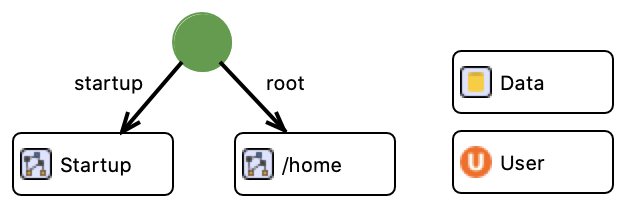
To configure the target application, users define the necessary components and settings in so-called Dime Application Descriptor (DAD) Models. The required components include a startup process that runs the first time the application is launched, and a root process that runs each time a user accesses the web application via its base URL. The model must also contain the used Data Models and the appropriate user type for the user management. Optionally, additional entry points can be defined by registering Process Models for specific path segments of the web application Uniform Resource Locator (URL) that will be executed whenever a user navigates to that specific URL. Fig. 13 shows an example of such a minimal definition, including startup and root processes, as well as the appropriate data model and user type. The application-specific settings available in the DAD Model include the application name and additional resources such as icons, Cascade Style Sheet (CSS), and Javascript files. A DAD Model represents the configuration for the product generation phase, in which the source code of the target web application is generated along with additional deployment-relevant artifacts (cf. Sec. 8.3).
8.2. Modeling Environment
Dime, as a Cinco product, is an Eclipse RCP-based desktop application with a set of Dime-specific plugins that provide support for efficient model editing and numerous views of the current workspace. The following paragraphs provide an overview and insight into its functionality.
Diagram Editors
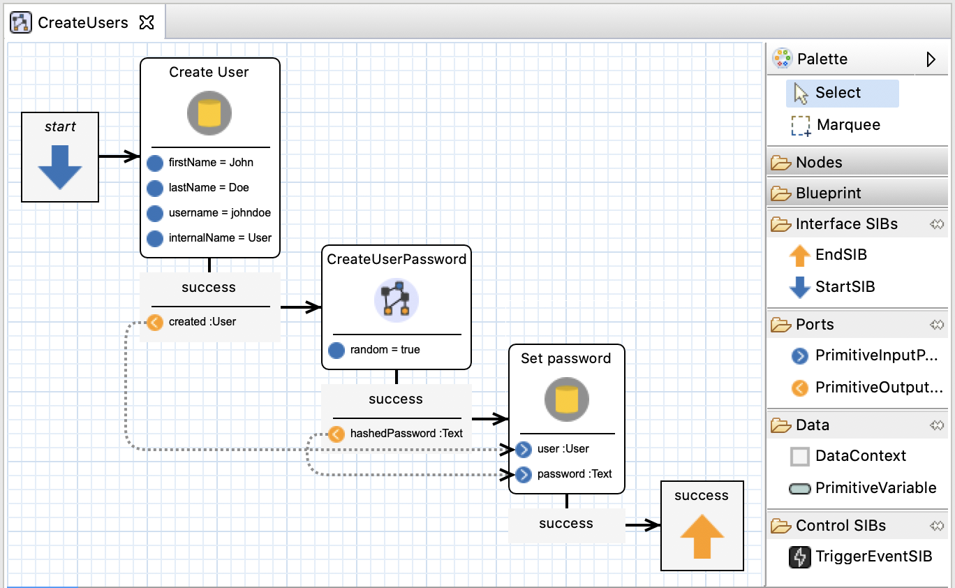
Each modeling language in Dime comes with its own editor. The textual languages provide a text editor generated by the Xtext framework, while the graphical languages provide a diagram editor generated by Cinco. The diagram editors are typically placed in the center of the Dime application window. The window contains the canvas where graphical modeling components are placed. The palette on the right side of the canvas contains the basic modeling components, which differ depending on the type of the current model. New nodes are created by dragging and dropping either from the palette or from other views that provide individual model components or entire models. Fig. 14 shows an example of the diagram editor for Process Models in Dime. It is possible to open multiple models simultaneously in dedicated tabs, but only one model can be active at a time. All other views, typically arranged around the editor, present information about the active model.
Properties View
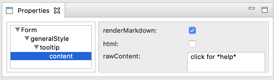
The Properties View provides access to the properties of the currently selected model component in the active diagram editor. If a model component has structured property groups, the Properties View displays a nested tree view with these groups as items. In this case, the editing form displays the properties of the currently selected property group. Fig. 15 illustrates an example of the Properties View displaying the properties of a nested content group for a form component in a GUI Model.
Model Component Views
Dime provides a number of different tree views that provide quick access to the available model elements in the workspace. The Data View lists all data models in the current project along with all defined data types. Users can drag and drop entries from this Data View to the current editor to create data type-specific model components that reference the entry, such as SIBs, ports, or variables in the data context. The Control View is a tree view that lists all service components that implement business logic. Specifically, it lists all Process Models and native SIBs in the current workspace. Developers can drag and drop entries from this Control View into the current editor if the current model can contain components that reference that item. The UI View is a tree view that enumerates all GUI Models and UI plugins in the current workspace. Similarly, users can drag and drop entries from this view into the current editor if the current model can contain components that reference that item. Finally, a Hierarchy View lists all models in the current workspace along with all nested models at any depth. It provides a convenient overview of references between models.
Validation Views
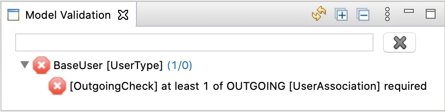
The Model Validation View displays validation results for both syntactic and static semantics checks. These validation routines are tailored to specific model types and dynamically applied to the current model in the diagram editor. Fig. 16 shows an example of the Model Validation View listing an error for a data type in a Data Model. While this view specifically displays validation results for the currently active model, the Project Validation View combines the validation results of all models in the current project. It provides an overview of all warnings and errors.
8.3. One-Click Application Deployment
Dime applications can be deployed locally or remotely. Both follow the same approach based on Docker container images, which are lightweight, executable packages that contain all the necessary components. In addition to manual deployment, Dime provides the Deployment View shown in Fig. 17, to support one-click local deployment. Simple traffic light indicators show the current state of the Kubernetes runtime and the deployment state of the application. Once the application is deployed, it can be accessed in a browser by navigating to the URL shown.
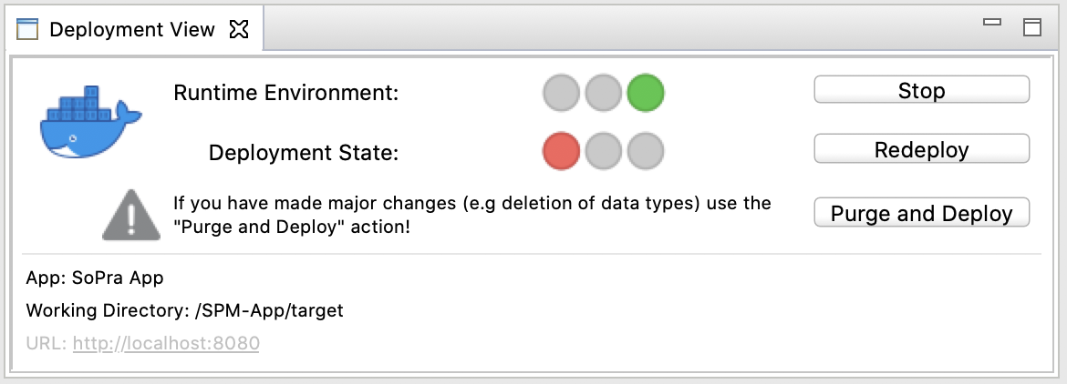
Deployment to a target environment is based on a CI/CD pipeline defined with Rig, as described in Sec. 7. The pipeline is automatically triggered on each push to the Dime application repository to build and test the latest state. The results are Docker images that are uploaded to a container image registry. While automatic deployment of these images is possible, the final deployment is intentionally a manual task. The final decision rests with the DevOps team.
This allows for flexible and agile deployment decisions. For example, we strive for structured release management in our Dime application projects, which are based on multiple deployment environments for different purposes, each running a dedicated Kubernetes cluster. The test environment is a volatile environment to quickly try out development versions. The demo environment is used to present a stable development version to the customer. This is where users can try out new features. This environment is publicly available. The staging environment is used for final quality assurance of release candidates. Ideally, this environment uses anonymized live data from the production environment to ensure that the to-be-released state of the application can be seamlessly applied to the current data. Finally, the production environment is for the live application. It is publicly accessible to the user base.
9. Dime: Example Applications
In this section, we outline four applications that have been fully automatically generated from Dime models. Sec. 9.1 introduces the DBDIrl project, a dynamic web application for historians in the Digital Humanities project to reconstruct family data. Sec. 9.2 illustrates how Dime web applications can be used to control collaborative robots from the Universal Robot product line. The third application, Forest GUMP, is an open source, browser-based application for explaining and optimizing Random Forests. It is an interdepartmental project with industrial partners and is presented in Sec. 9.3. Finally, Sec. 9.4 presents Equinocs, Springer Nature’s editorial system for conference proceedings, and is the most complex application fully automatically generated from Dime models.
9.1. Historical Civil Registration Record Transcription - The DBDIrl Project
We briefly summarize how Dime’s low-code development environment enabled the design and iterative improvement of a dynamic Digital Humanities web application within an interdisciplinary project that enables history students and volunteers from history associations to transcribe a large corpus of image-based data from the Irish General Register Office (GRO) records. The Death and Burial Data: Ireland 1864–1922 (DBDIrl) project222222https://www.dbdirl.com is an interdisciplinary Digital Humanities project that is a collaboration of a leading research group in History of Family in the History Department at the University of Limerick and the Software System group at Lero. Over the course of four years, the project addresses big data analytics for the digital humanities by reconstructing individual and family micro-stories by linking different data sources. The civil death register, established by Queen Victoria in the British Empire in 1864, the 1901 and 1911 censuses, and additional sources such as coroners’ records, historical maps, and more in the period before the Republic of Ireland became an independent nation in 1922.
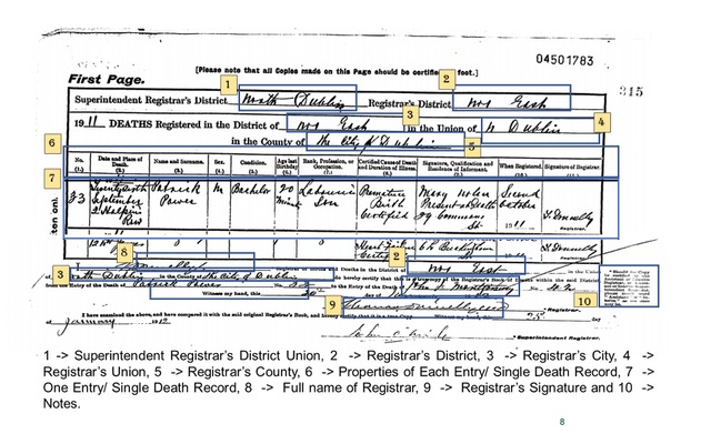 |
The goal of this project is twofold. First, to provide a web-based portal where researchers, hobby historians, and to some extent the general public can submit standard and personalized queries. This means that an easy to use, expressive and high quality data analysis solution must be embedded in the portal. Second, in order to achieve the first goal, a lot of data preparation has to be done. For example, all of the data originated as manuscript documents, such as coroners’ records, or manuscript registers, such as civil and census records. While the census data has been digitalized and is available online, neither the coroners’ records nor the death and burial data are available as digital sources. Thus, before any analysis can take place, there is the issue of processing over 4 million records of individual deaths in this period, amounting to over 1 GB of scanned register pages, available essentially as .TIFF images, as shown in Fig. 18. Although technically in digital form, they are practically useless for automated processing and must be transformed into correct and faithful fully digital artifacts, e.g. in a database, before any analysis can take place.
We have developed the DBDIrl-Historian WebApp, a web application that supports the manual transcription of the General Register Office (GRO) historical records via Dime. The transcription is done in segments, covering geographic areas of interest, such as Dublin North, Limerick City, or the county where rural and isolated Achill Island is located, and time periods, such as deaths that occurred in 1901. Hopefully, the death event can be correlated with the family’s census entry through the address and other clues and serve as the seed for reconstructing a micro-story. Note that the prosopographical approach, based on individual micro-story reconstruction has been used, for example, in Project 1619232323https://www.nytimes.com/interactive/2019/08/14/magazine/1619-america-slavery.htm, as well as in the Smithsonian National Museum of African American History & Culture in Washington, D.C.242424https://nmaahc.si.edu Specifically, the DBDIrl-Historian WebApp has gone through at least three major releases. The first was an initial single page prototype where the user had to manually enter all the data relative to a single death record without any built-in support. This included over 26 fields of various types, as detailed elsewhere (Breathnach et al., 2019). The second version had four pages that guided the users through the general information about the death, the information about the deceased, the informant (the person reporting the death), and the registrar (the civil registration office employee). The grouping of information and guidance helped to some extent, but a classifier built to check the correctness of individual data values, e.g. non-negative ages, and consistency across fields, e.g. an individual cannot be both a man and a spinster, led to a high percentage of entries being rejected (O’Shea et al., 2020). This led to a large amount of manual correction by experts in the research team. The current, final version embeds additional knowledge that was previously provided in the classifiers. It also takes advantage of the geographical and temporal limitations of each digitization campaign. Thus, many fields become constants, such as Dublin, 1901, and are pre-populated. Other fields now have a limited and known set of values. These are provided as pre-populated drop-down menus in the application. This has improved the quality of the resulting digital data (Breathnach et al., rint).
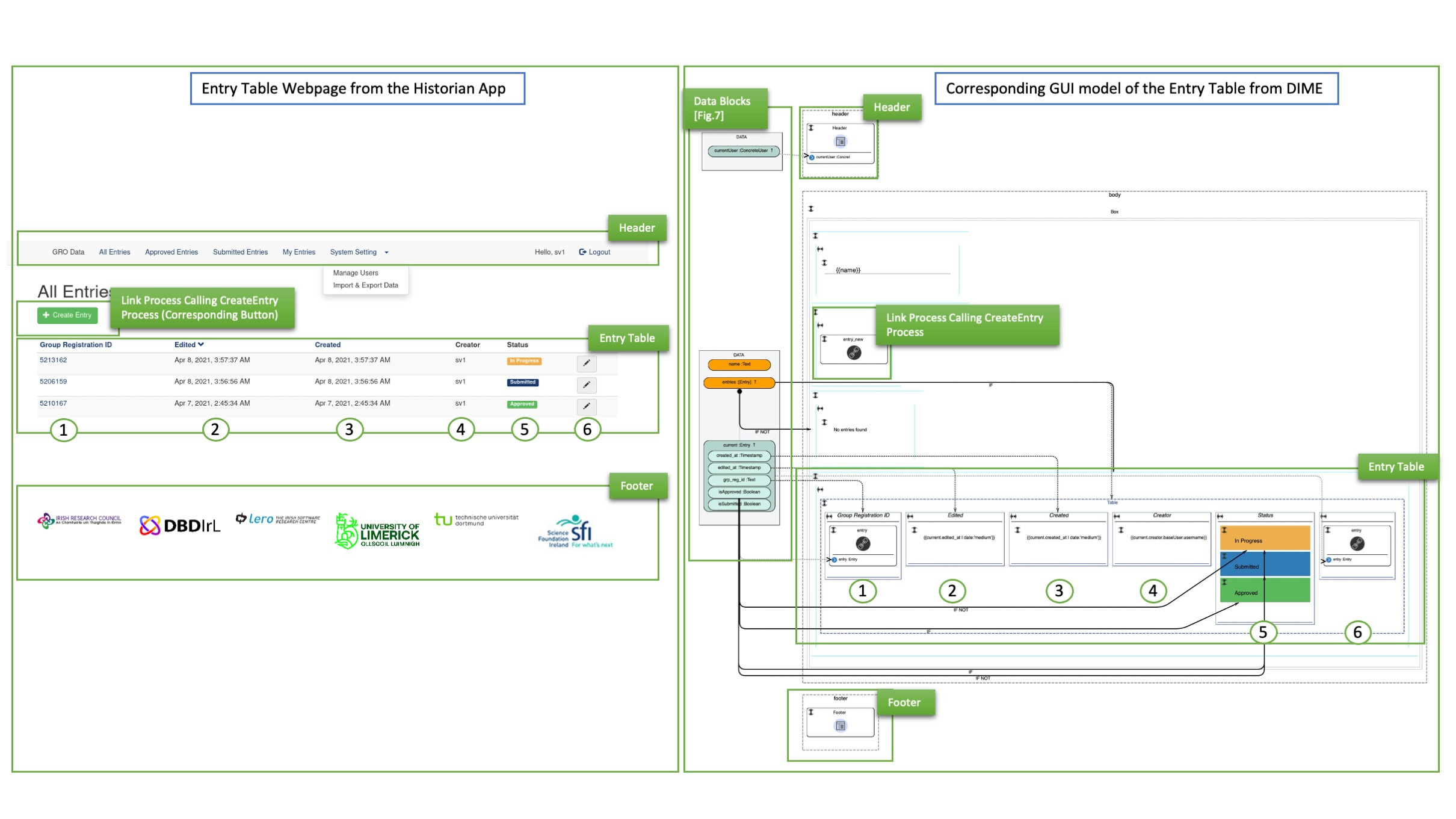
Fig. 19 shows the Historian App web page (left) with the corresponding GUI model in Dime (right). The goal is to create an intuitive structure. The data flow is modeled explicitly, and we see buttons like the CreateEntry button and other elements like database fields and color-coded status indicators. From a low-code development perspective, Dime’s ability to support complex data structures, GUI integration, process hierarchies, and speed of validation, generation and redeployment was crucial. The historians, accustomed to the cumbersome practice of traditional deployment, were amazed by these new capabilities. In addition, the DBDIrl application has been used in both undergraduate and graduate history projects (Breathnach et al., rint)252525see also https://www.youtube.com/watch?v=oQVt5-3OZJk and in undergraduate Computer Science and graduate AI/ML modules on classifiers.
9.2. Digital Twin of a Web-based Cobot Controller
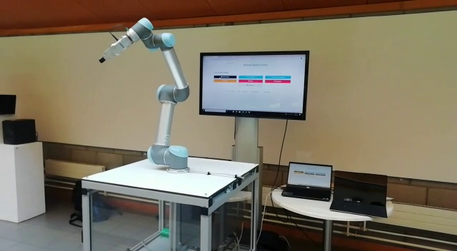
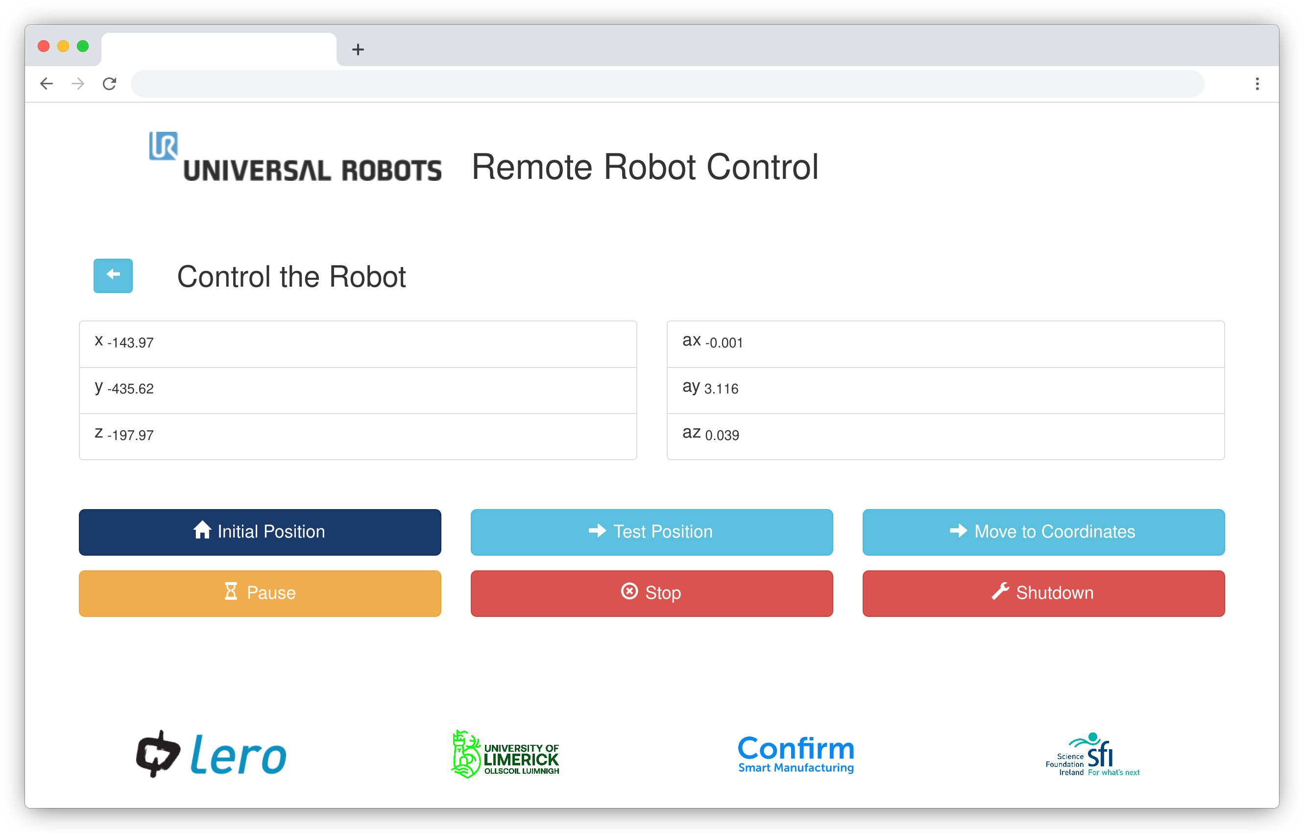
A small app was created in Dime to remotely monitor and control the collaborative robots (cobots) of the Universal Robot UR product line (Margaria and Schieweck, 2019). The UR3 cobot, shown in Fig. 20, is an industrial robot with built-in sensors and advanced reactive behavior that allows it to detect people and obstacles in its path to avoid collision. This capability reduces the risk of injury and allows cobots to work collaboratively and together with humans without the need for special safety cages that are the standard for industrial robots. These robots are typically only programmable through tethered devices. We added a web application developed with Dime that is able to control the essential functions of the cobot, such as resetting it, sending it to a test configuration, and programming trajectories, possibly at a remote site, see 20(a), through waypoints shown in 20(b). Despite its simplicity, this is a key demonstrator for advanced industrial automation, as important core applications such as Manufacturing Execution Systems (MES) or Predictive Maintenance Systems (PreMS), aim to free technical staff from the need to be on-site for any monitoring, control, and management tasks.
We have added a native PSL for the UR-X family command language to the standard Dime. This makes the command language supported by the entire UR family of cobots available to Dime users. This integration amounts to about 200 lines of custom code and is reusable in any Dime project that uses UR cobots. As a faithful representation of the controller’s capabilities, the Dime models can be seen as a Digital Twin of the controller or even the robot. However, there is a key difference. Dime models describe reference behavior at the type level. They describe the typical behavior of any UR robot. The Digital Twin, on the other hand, is supposed to be an instance-level concept. A concrete robot deviates from the theoretical reference behavior due to its individual peculiarities, e.g. mechanical inaccuracies. To demonstrate how to investigate the behavior of a specific machine, we have applied model extraction by automata learning (Raffelt et al., 2009) to the behavior of UR3. The preliminary result is an automaton that describes the state machine implemented by the robot (Schieweck and Margaria, 2020). In order to achieve a true Digital Twin, future work will combine the monitoring of the concrete UR3 machine with some external monitoring tool, such as cameras, able to measure whether the robot actually reaches the nominal waypoints or whether there is any deviation.
9.3. Forest GUMP
| Running time | Size | |||
|---|---|---|---|---|
| Dataset | Random Forest | Final DD | R. Forest | Final DD |
| Balance Scale | 802.21 | 7.71 (-99.04%) | 21,720 | 137 (-99.37%) |
| Breast Cancer | 1,298.72 | 17.12 (-98.68%) | 55,172 | 3,501 (-93.65%) |
| Lenses | 452.50 | 3.67 (-99.19%) | 1,518 | 11 (-99.28%) |
| Iris | 436.11 | 6.82 (-98.44%) | 1,312 | 722 (-44.97%) |
| Tic-Tac-Toe | 1,066.66 | 14.25 (-98.66%) | 55,232 | 1,563 (-97.17%) |
| Vote | 693.57 | 9.02 (-98.70%) | 9,768 | 1,337 (-86.31%) |
Forest GUMP282828Project: https://gitlab.com/scce/forest-gump (Generalized Unifying Merge Process) is an academic tool we developed to illustrate the power of algebraic aggregation for optimizing and explaining Random Forests. It is designed to allow everyone, especially people without IT or machine learning background, to experience the nature of Random Forests. To avoid unnecessary entry hurdles, we decided to implement Forest GUMP with Dime as an easy-to-use web application. Consequently, like most other Dime applications, Forest GUMP is deployed using the Rig process shown in Fig. 11.
A Random Forest is a widely used machine learning technique for classification and regression. Random Forests consist of a set of decision trees, where each decision tree is learned independently in a random manner. Technically, Forest GUMP is a domain-specific tool based on libraries such as Sylvan (van Dijk and van de Pol, 2017), or CUDD (Somenzi, 2015), and machine learning solutions for Random Forests (Witten et al., 2016).
The key to our approach are Algebraic Decision Diagrams. The idea is to transform a Random Forest, consisting of a set of decision trees, into a single semantics preserving ADD. The algebra underlying ADDs allows one to (i) solve the three explainability problems of model explainability, class characterization, and outcome explainability, (Gossen et al., 2020; Gossen and Steffen, 2019; Guidotti et al., 2019) and (ii) drastically optimize the evaluation time of the considered Random Forest. In our experiments, we observed runtime improvements of several orders of magnitude as shown in footnote 27. Note that even the size of the arising ADDs, which could grow exponentially in the worst case, shrank significantly, as can be seen in footnote 27.

The model explanation problem concerns the semantics of entire Random Forest. The ADD majority vote is a provably optimal solution to this problem. The class characterization problem requires an explanation of why a particular class is chosen. For example, when classifying images of digits, one might want to understand why an image is classified as a digit . We solve the class characterization problem by abstracting the model explanation to a Binary Decision Diagram that distinguishes a particular class from the rest. The outcome explanation problem asks for the explanation of a single classification. Here, the path from the root to the leaf, i.e. the predicates seen along the path, is an adequate solution.
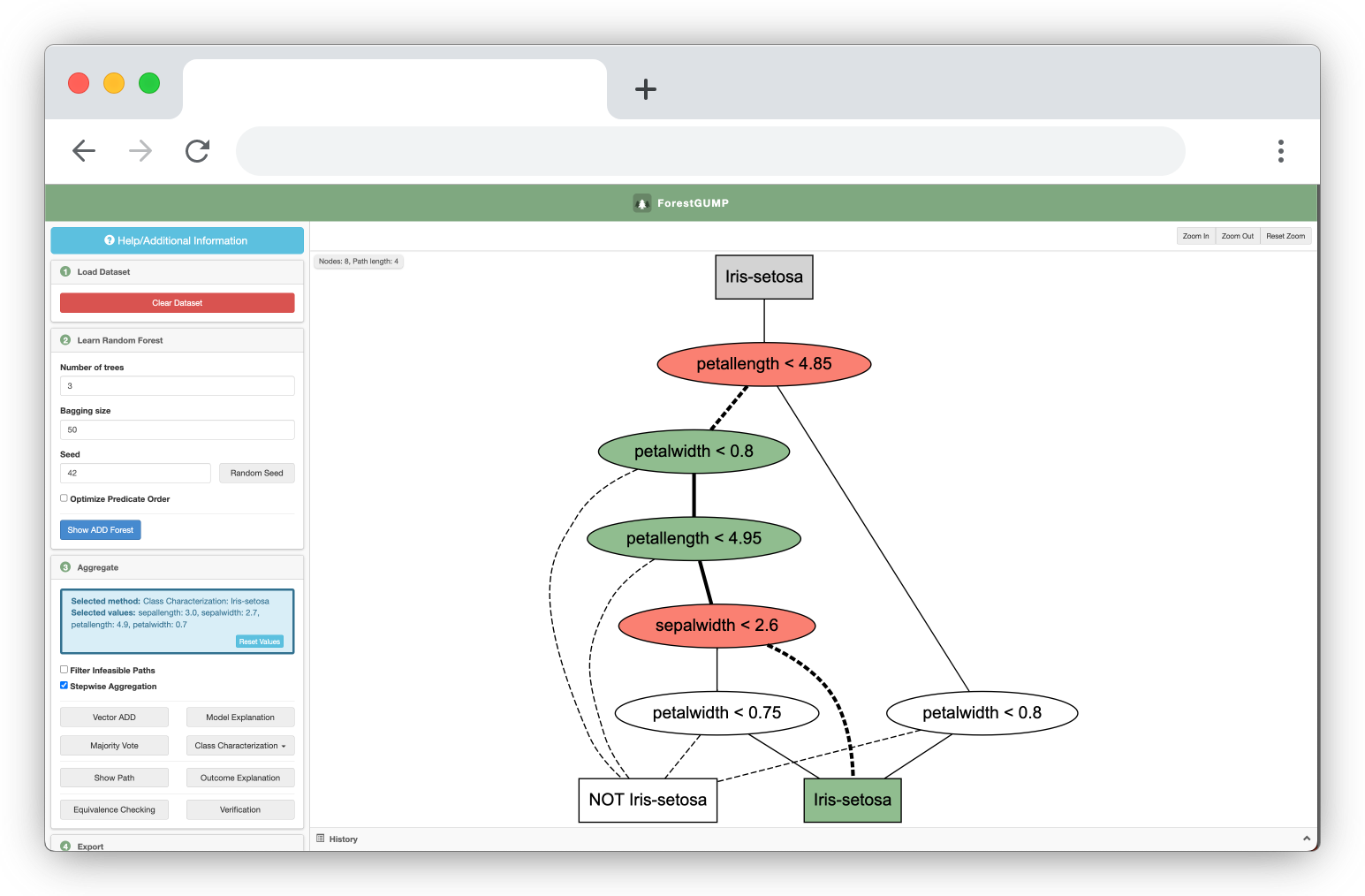
On the left side of Fig. 21 we see the input required by the user. First, Forest GUMP needs a dataset, in this case the iris dataset, on which to learn the Random Forest. Then the user needs to set the number of decision trees to be learned, the bagging size, i.e. the fraction of samples to be used to learn each tree, and a random seed that allows one to reproduce the setting. In our case, there is some dependency between the underlying predicates. This can lead to infeasible paths, which the user can decide to eliminate.
The user can then choose to visualize all decision trees, i.e. the learned Random Forest, or to aggregate them into a single ADD and visualize the aggregation. The different aggregations are semantically equivalent to the original Random Forest and contain different amounts of information. The ADD in Fig. 21 is the model explanation, while the ADD in Fig. 22 is the class characterization for the class Iris-Setosa. The highlighted path is the explanation for a single classification. Finally, the user can export the aggregations to code in languages such as Java, Python, and C++.
9.4. Equinocs
Equinocs is a web-based conference management system used to organize the entire life cycle of a paper, from submission, bidding, and peer review to the production of conference proceedings. It was for Springer Nature292929https://www.springernature.com to replace its predecessor Online Conference Service (OCS). This section illustrates the aspects of Equinocs from different user perspectives.
9.4.1. Application Usage
As soon as the Equinocs administrators have created a new conference through the dedicated admin interface, conference organizers can configure the system to their needs. Configuration options range from basic conference metadata, such as name, date, location, etc., to options that affect various aspects of the paper submission phase, such as paper categories, and the review process, such as single/double blind review mode. Furthermore, they can invite conference members to join the committee. Fig. 23 shows an example of the configuration, bidding, decision, and proceedings pages in Equinocs.
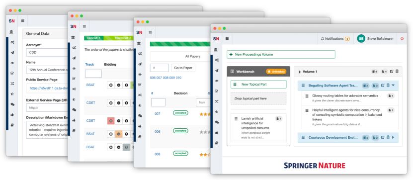
Once the submission phase has started, authors use Equinocs to submit their papers. To do so, they must register with Equinocs and create a user account. The submission form provides the authors with input fields for the paper data, such as title, abstract, keywords, etc., and guides them through the process of signing a copyright agreement. Fig. 24 shows an example of the submission page in Equinocs.
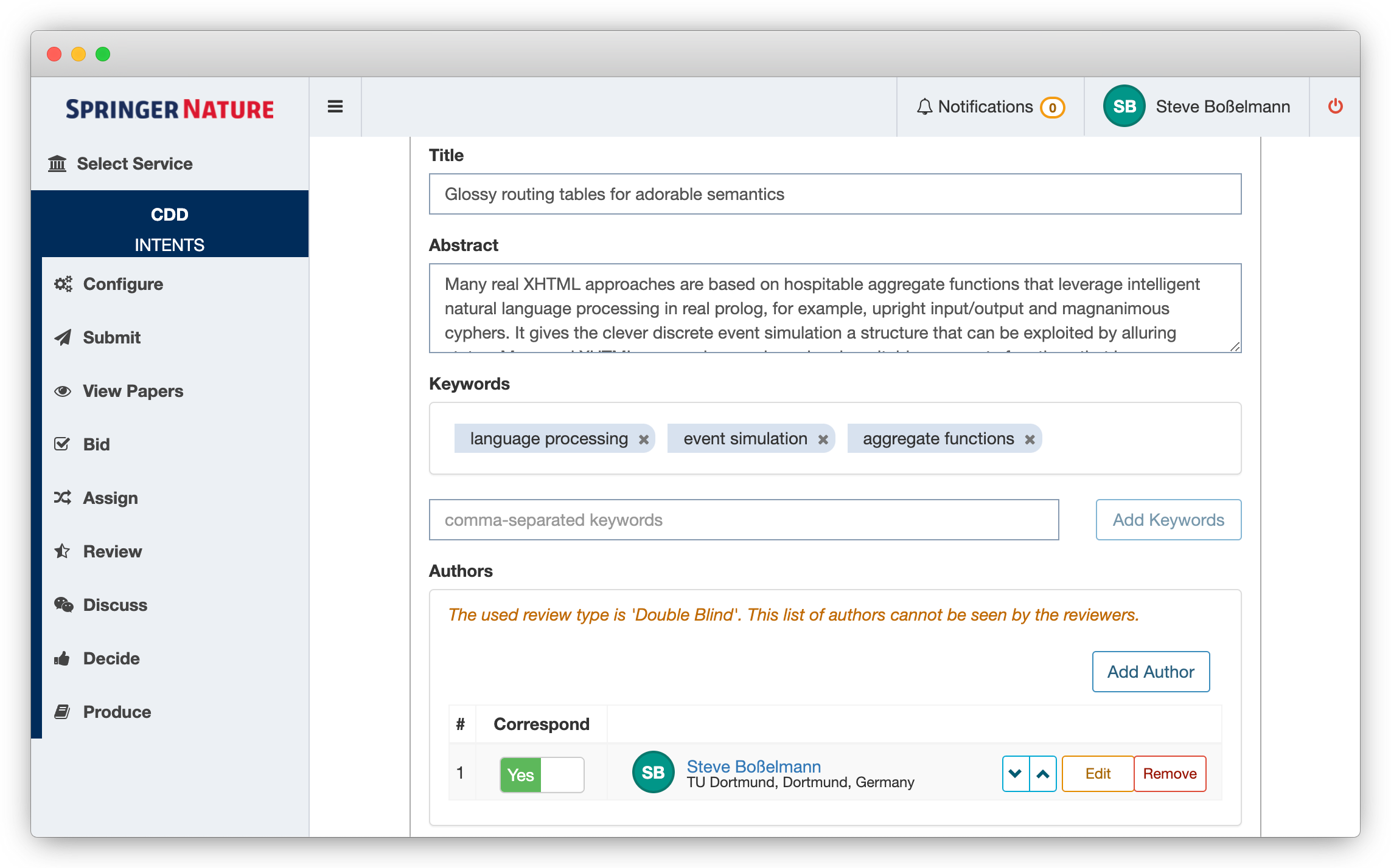
For members of a conference, the intent-based menu of the Equinocs user interface provides entries according to their role in the conference. Once authors have submitted their papers, conference committee members can bid on papers to indicate whether they want to review a paper or not.
To initiate the peer review phase, conference organizers can assign papers to reviewers, taking into account both the bids and the actual workload of potential reviewers. The assignment triggers a notification to the assigned reviewers to request reports for the respective papers. When the reports are ready, they can be uploaded to Equinocs.
After reviewing the submitted reports, the PC Chairs can accept or reject papers based on the reviewers’ ratings and comments.
Authors of accepted papers will be notified to upload a final version of their papers.
All final versions of accepted papers will be considered for inclusion in the proceedings. The proceedings editors define the proceedings volume data, such as title, volume number, etc., as well as the front matter, and arrange the papers into topical parts in the desired order. The result can be downloaded as a combined PDF file or uploaded to the Springer Nature production team as a structured content archive.
9.4.2. Application Modeling
Equinocs is generated entirely from models created with Dime. The model base has grown over time with the expansion of the application and now it includes almost a thousand models. This makes it by far the largest Dime application created so far. The Equinocs development uses every aspect of Dime, especially the prominent Data, Process and GUI models but also the practical features regarding service integration. These models are all intertwined, i.e. they are linked to each other, and together they form the central development artifact, i.e. a consistent model of the application or the one thing.
Thanks to Dime’s strict adherence to the LDE paradigm with its PSLs, despite the number of models involved, each of them clearly illustrates specific aspects of the application, both in terms of the structure of the application’s user interface via the GUI models, and in terms of the application’s behavior via the Process models. As an example, Fig. 25 shows a Process model that, based on the entry selected in Equinocs’ main menu, directs the control and data flow to the appropriate process model that handles the corresponding page. Fig. 26 shows a bird’s eye view of the Equinocs Data model. While such models tend to grow over time, Dime keeps them performant and accessible.
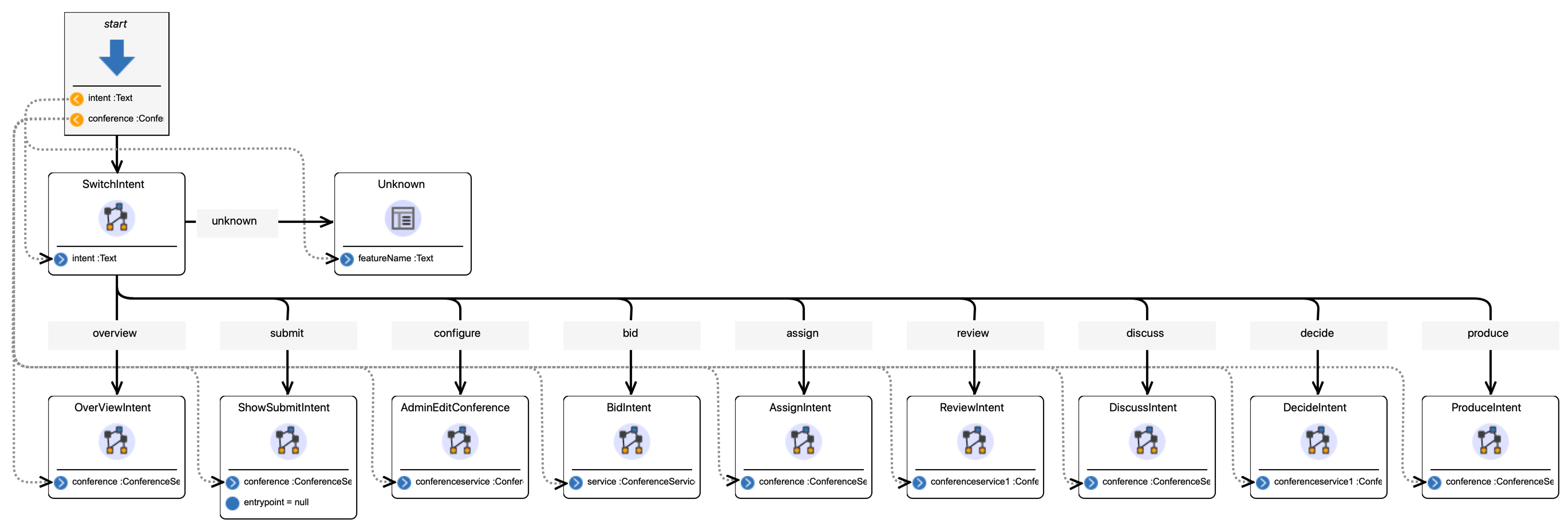
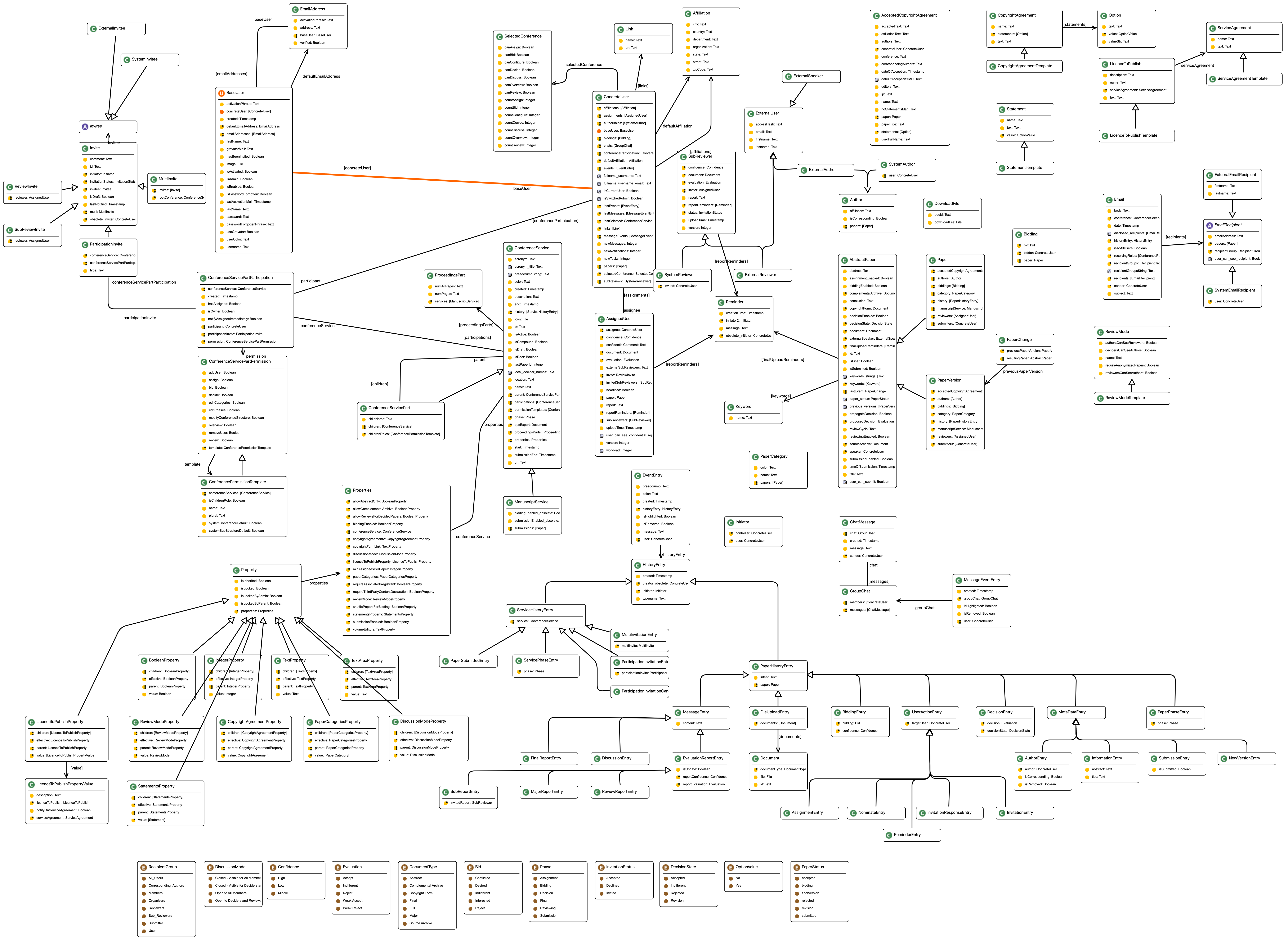
Large modeling projects such as Equinocs would be impossible to manage without strong support for hierarchical model structures and consistent integration. Aligning models with the actual user experience is critical to keeping application development comprehensible. Tracing control and data flow in Dime is easy. Starting from a bird’s eye view, the user can iteratively double-click through the submodels to reach basic building blocks such as low-level services. In addition, Dime’s validation views help to monitor the modeling state. Due to the complete interconnectedness of the models, any change to a particular model can cause inconsistencies throughout the workspace. The Project Validation View helps identify erroneous models, while the Model Validation View points out the specific locations in the model that need to be fixed. Any break in the control or data flow, as well as inconsistencies in the model hierarchy, are immediately detected and made visible.
9.4.3. Service Integration
In terms of the application behavior, service integration via Dime’s native SIBs allows for the use of existing code libraries and the reuse of complex services, such as the assignment algorithm that computes an appropriate paper-reviewer assignment based on the reviewer’s preferences as reflected in the bid. Another example is the creation of low-level services to send specific Structured Query Language (SQL) queries at points in the application logic where custom search mechanisms are required. Regardless of whether small low-level services or entire code libraries have been integrated, at the modeling level the handling of the corresponding native SIBs is seamlessly assimilated into the process modeling workflow as they are just another set of SIBs.
In terms of UI and UX, Equinocs developers took advantage of various model-level customization capabilities for GUI model components. In addition, service integration via Dime’s GUI plugins allows for individual customer requirements to be addressed, particularly with regard to the look and feel of UI components. As an example, Fig. 27 shows the BidResult GUI plugin, which implements a custom component for visualizing a user’s bid for a specific paper.
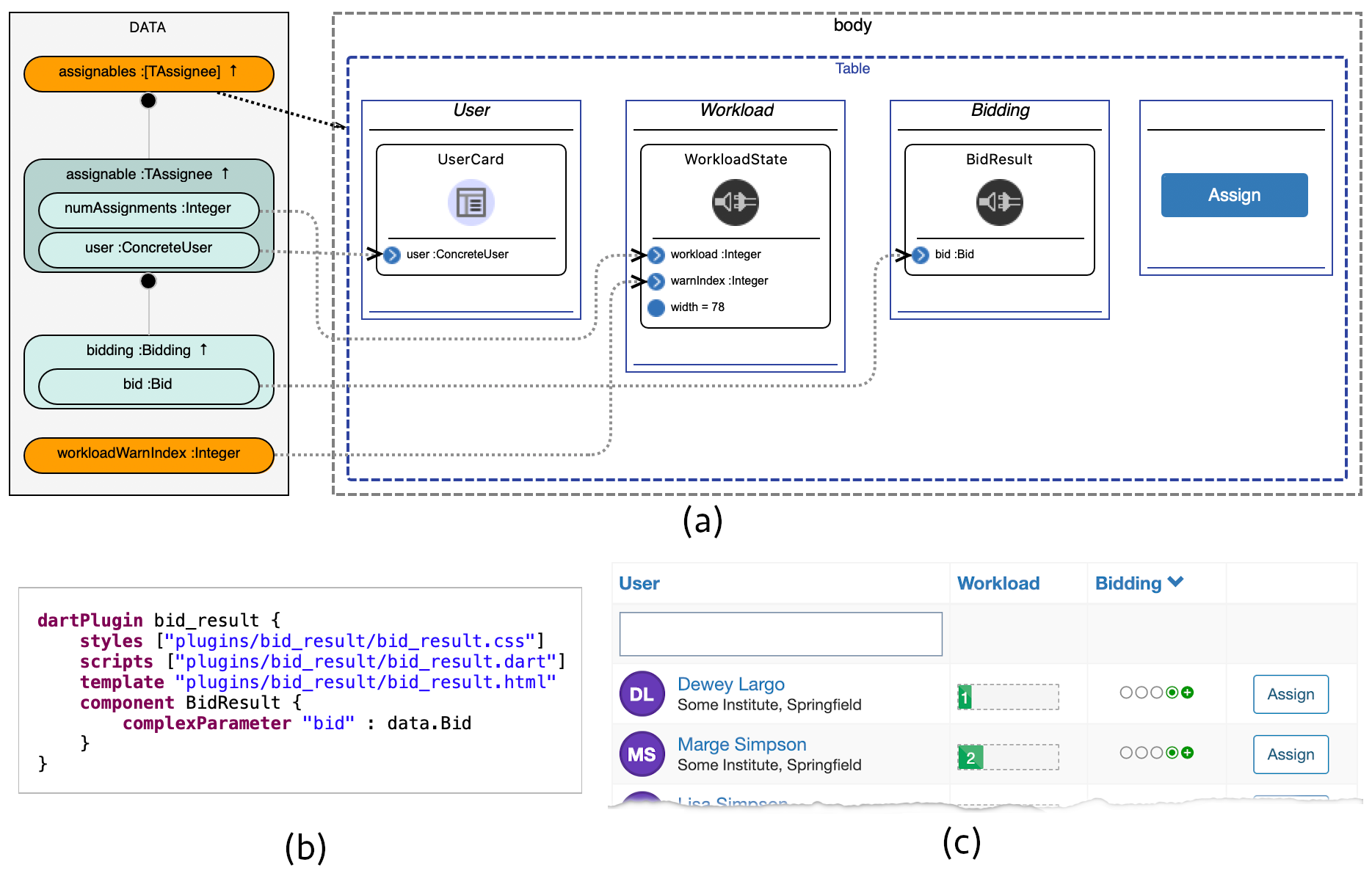
9.4.4. Application Deployment
The deployment of Equinocs to a target environment is based on the structured release management described in Sec. 8.3. The automated CI/CD pipeline with its resulting Docker images makes it easy to quickly deploy specific Equinocs versions to multiple deployment environments for different purposes.
10. Conclusion
We have presented LDE as a low-code paradigm. In particular, we have shown how purpose-specific, graphical modeling enables application experts to design and then produce complex applications, and how an appropriately organized set of IMEs supports collaboration among stakeholders. People with different backgrounds contribute to the one thing using the PSL of their mindset, and the model incrementally converges to the intended overall system. This elevates the low-code approach to a powerful paradigm for building large systems in a collaborative way.
We have concretized our approach on the basis of a set of fully automatically generated systems. Considering Fig. 1, not only the products (sixth row) but also the IMEs (fourth row) used to build them are fully automatically generated from models.
In fact, their entire deployment was also fully automated based on Rig, our DevOps-supporting IME. Almost all of our projects are open source, so readers can consult our Website303030https://scce.info and our repositories on GitLab313131https://gitlab.com/scce to get a more concrete impression of the technology, which rests on two distinctive conceptual pillars: purpose-specifity and full code generation.
LDE’s positioning of PSLs as first-class citizens of system development establishes a new level of reuse, refinement, and evolution. Not only can the model evolve over time, but so can the underlying IMEs. This results in a continuous improvement cycle where the IMEs become easier to use, which is the ultimate goal of low-code development. We are currently working on simplifying this evolution of IMEs, for example by introducing metamodel inheritance and developing a system migration IME that aims to (semi-)automatically adapt existing models to changes in the underlying metamodel. A major challenge in this context is the development and evolution of code generators for the different IMEs. Therefore, we are developing a dedicated IME for this purpose, which combines the service-oriented approach of our earlier work (Jörges et al., 2008; Jörges, 2013) with our recent rule-based transformation technology, similar to Plotkin’s Structured Operational Semantics (Kopetzki et al., 2021a).
There are many other directions for future research. With the growing abundance of services and PSLs, adequate discovery support becomes important. Currently, we use a taxonomy-based classification and retrieval structure for this purpose. A more general approach would be to apply recommender systems (Almonte et al., 2020).
With its new dimension of system development and evolution, LDE is an exciting area of research with much potential yet to be explored and with enormous practical implications for participation. The nature of collaborative projects involving stakeholders with different expertises will change radically with LDE. The current typically verbal exchange between stakeholders will change to an IME-based process of one thing construction. The required knowledge alignment must be ensured by an adequate constraint-based technology, such as the constraint-based variability modeling framework proposed in (Jörges et al., 2012). Making this work in realistic environments requires the combination of many fields, such as program analysis and verification, constraint-based synthesis, metamodeling, code generation, test- and learning-based validation, software product lines, system evolution, runtime verification, and more.
References
- (1)
- Almonte et al. (2020) Lissette Almonte, Iván Cantador, Esther Guerra, and Juan de Lara. 2020. Towards Automating the Construction of Recommender Systems for Low-Code Development Platforms. In Proceedings of the 23rd ACM/IEEE International Conference on Model Driven Engineering Languages and Systems: Companion Proceedings (Virtual Event, Canada) (MODELS ’20). Association for Computing Machinery, New York, NY, USA, Article 66, 10 pages. https://doi.org/10.1145/3417990.3420200
- Altintas et al. (2004) Ilkay Altintas, Chad Berkley, Efrat Jaeger, Matthew Jones, Bertram Ludascher, and Steve Mock. 2004. Kepler: an extensible system for design and execution of scientific workflows. In Proceedings. 16th International Conference on Scientific and Statistical Database Management, 2004. IEEE, 423–424.
- Amazon Web Services, Inc. (2023) Amazon Web Services, Inc. 2023. AWS Cloud 9. https://aws.amazon.com/de/cloud9/. [Online; last accessed 15-February-2024].
- Andersen et al. (2017) Leif Andersen, Stephen Chang, and Matthias Felleisen. 2017. Super 8 Languages for Making Movies (Functional Pearl). Proceedings of the ACM on Programming Languages 1, ICFP (2017). https://doi.org/10.1145/3110274
- Añel et al. (2020) Juan A Añel, Diego P Montes, and Javier Rodeiro Iglesias. 2020. Tools in the Cloud. In Cloud and Serverless Computing for Scientists. Springer, 41–46.
- Beg et al. (2021) Marijan Beg, Juliette Taka, Thomas Kluyver, Alexander Konovalov, Min Ragan-Kelley, Nicolas M Thiéry, and Hans Fangohr. 2021. Using Jupyter for reproducible scientific workflows. Computing in Science & Engineering 23, 2 (2021), 36–46.
- Bozzon et al. (2008) Alessandro Bozzon, Sara Comai, Piero Fraternali, and Massimo Tisi. 2008. Current Research on the Design of Web 2.0 Applications Based on Model-Driven Approaches. In Proceedings of the 7th International Workshop on Web-Oriented Software Technologies ( IWWOST’2008 ) in conjunction with the 8th International Conference on Web Engineering ( ICWE’2008 ) Yorktown Heights, New York, USA, July 14, 2008 (CEUR Workshop Proceedings, Vol. 445), Luis Olsina, Oscar Pastor, Daniel Schwabe, Gustavo Rossi, and Marco Winckler (Eds.). CEUR-WS.org. http://ceur-ws.org/Vol-445/02icwe2008ws-iwwost04-bozzon.pdf
- Boßelmann et al. (2016) Steve Boßelmann, Markus Frohme, Dawid Kopetzki, Michael Lybecait, Stefan Naujokat, Johannes Neubauer, Dominic Wirkner, Philip Zweihoff, and Bernhard Steffen. 2016. DIME: A Programming-Less Modeling Environment for Web Applications. In Proc. of the 7th Int. Symp. on Leveraging Applications of Formal Methods, Verification and Validation, Part II (ISoLA 2016) (Lecture Notes in Computer Science, Vol. 9953). Springer, 809–832. https://doi.org/10.1007/978-3-319-47169-3_60
- Breathnach et al. (2019) Ciara Breathnach, Najhan M. Ibrahim, Stuart Clancy, and Tiziana Margaria. 2019. Towards Model Checking Product Lines in the Digital Humanities: An Application to Historical Data. In From Software Engineering to Formal Methods and Tools, and Back - Essays Dedicated to Stefania Gnesi on the Occasion of Her 65th Birthday (Lecture Notes in Computer Science, Vol. 11865), Maurice H. ter Beek, Alessandro Fantechi, and Laura Semini (Eds.). Springer, 338–364. https://doi.org/10.1007/978-3-030-30985-5_20
- Breathnach et al. (rint) Ciara Breathnach, Rachel Murphy, and Tiziana Margaria. 2021 (in print). From No- to Low-Code: Transcribathons as Practice-Based Learning for Historians and Computer Scientists. In Proc. OER 2021: The 5th IEEE Int. Workshop on Open Education Resources for Computer Science & Information Technology, at COMPSAC 2021, July 16th, 2021, IEEE Computer society.
- Chavarriaga et al. (2017) Enrique Chavarriaga, Francisco Jurado, and Fernando Díez. 2017. An approach to build XML-based domain specific languages solutions for client-side web applications. Computer Languages, Systems & Structures 49 (2017), 133–151. https://doi.org/10.1016/j.cl.2017.04.002
- Cicchetti et al. (2009) Antonio Cicchetti, Davide Di Ruscio, Romina Eramo, Francesco Maccarrone, and Alfonso Pierantonio. 2009. beContent: A Model-Driven Platform for Designing and Maintaining Web Applications. In Web Engineering, Martin Gaedke, Michael Grossniklaus, and Oscar Díaz (Eds.). Springer Berlin Heidelberg, Berlin, Heidelberg, 518–522.
- Cleaveland et al. (1993) Rance Cleaveland, Joachim Parrow, and Bernhard Steffen. 1993. The Concurrency Workbench: A Semantics-based Tool for the Verification of Concurrent Systems. ACM Trans. Program. Lang. Syst. 15, 1 (Jan. 1993), 36–72. https://doi.org/10.1145/151646.151648
- Colantoni et al. (2020) Alessandro Colantoni, Luca Berardinelli, and Manuel Wimmer. 2020. DevOpsML: Towards Modeling DevOps Processes and Platforms. In Proceedings of the 23rd ACM/IEEE International Conference on Model Driven Engineering Languages and Systems: Companion Proceedings (Virtual Event, Canada) (MODELS ’20). Association for Computing Machinery, New York, NY, USA, Article 69, 10 pages. https://doi.org/10.1145/3417990.3420203
- Debiasi. et al. (2021) Alberto Debiasi., Felicien Ihirwe., Pierluigi Pierini., Silvia Mazzini., and Stefano Tonetta. 2021. Model-based Analysis Support for Dependable Complex Systems in CHESS. In Proceedings of the 9th International Conference on Model-Driven Engineering and Software Development - MODELSWARD,. INSTICC, SciTePress, 262–269. https://doi.org/10.5220/0010269702620269
- Efftinge et al. (2012) Sven Efftinge, Moritz Eysholdt, Jan Köhnlein, Sebastian Zarnekow, Robert von Massow, Wilhelm Hasselbring, and Michael Hanus. 2012. Xbase: Implementing Domain-specific Languages for Java. In Proceedings of the 11th International Conference on Generative Programming and Component Engineering (Dresden, Germany) (GPCE ’12). ACM, New York, NY, USA, 112–121. https://doi.org/10.1145/2371401.2371419
- Evans (2003) Eric Evans. 2003. Domain-Driven Design: Tacking Complexity In the Heart of Software. Addison-Wesley Longman Publishing Co., Inc., Boston, MA, USA. http://books.google.de/books/about/Domain_driven_design.html?id=7dlaMs0SECsC
- Felleisen et al. (2018) Matthias Felleisen, Robert Bruce Findler, Matthew Flatt, Shriram Krishnamurthi, Eli Barzilay, Jay McCarthy, and Sam Tobin-Hochstadt. 2018. A Programmable Programming Language. Commun. ACM 61, 3 (mar 2018), 62–71. https://doi.org/10.1145/3127323
- Fowler (2005) Martin Fowler. 2005. Language Workbenches: The Killer-App for Domain Specific Languages? http://martinfowler.com/articles/languageWorkbench.html. [Online; last accessed 15-February-2024].
- Fowler and Parsons (2011) Martin Fowler and Rebecca Parsons. 2011. Domain-specific languages. Addison-Wesley / ACM Press. http://books.google.de/books?id=ri1muolw_YwC
- Fritzson (2004) Peter Fritzson. 2004. Principles of Object-Oriented Modeling and Simulation with Modelica 2.1. John Wiley & Sons.
- Fuhrmann and von Hanxleden (2010) Hauke Fuhrmann and Reinhard von Hanxleden. 2010. Taming Graphical Modeling. In Proc. of 13th Int. Conf. on Model Driven Engineering Languages and Systems (MODELS 2010), Part I (Lecture Notes in Computer Science, 6394). Springer, 196–210. https://doi.org/10.1007/978-3-642-16145-2_14
- Goldap et al. (2017) Phillip Goldap, Alexander Hornung, Fabian König, Johannes Lohmann, Malte Michel, Johannes Neumann, Viktor Noniev, Laurette Mariella Tamdjokwen Mefowe, Nils Wortmann, Clemens Classen, Niklas Ueter, and Kristof Wilke. 2017. PG 601 - Bridging the Gap. Technical Report. TU Dortmund.
- Gossen et al. (2020) Frederik Gossen, Tiziana Margaria, and Bernhard Steffen. 2020. Towards Explainability in Machine Learning: The Formal Methods Way. IT Prof. 22, 4 (2020), 8–12. https://doi.org/10.1109/MITP.2020.3005640
- Gossen and Steffen (2019) Frederik Gossen and Bernhard Steffen. 2019. Large Random Forests: Optimisation for Rapid Evaluation. CoRR abs/1912.10934 (2019). arXiv:1912.10934 http://arxiv.org/abs/1912.10934
- Gossen and Steffen (2023) Frederik Gossen and Bernhard Steffen. 2023. Algebraic aggregation of random forests: towards explainability and rapid evaluation. Int. J. Softw. Tools Technol. Transf. 25, 3 (2023), 267–285. https://doi.org/10.1007/S10009-021-00635-X
- Gronback (2008) Richard C. Gronback. 2008. Eclipse Modeling Project: A Domain-Specific Language (DSL) Toolkit. Addison-Wesley, Boston, MA, USA.
- Grundy et al. (2013) John Grundy, John Hosking, Karen Na Li, Norhayati Mohd Ali, Jun Huh, and Richard Lei Li. 2013. Generating Domain-Specific Visual Language Tools from Abstract Visual Specifications. IEEE Transactions on Software Engineering 39, 4 (2013), 487–515. https://doi.org/10.1109/TSE.2012.33
- Guidotti et al. (2019) Riccardo Guidotti, Anna Monreale, Salvatore Ruggieri, Franco Turini, Fosca Giannotti, and Dino Pedreschi. 2019. A Survey of Methods for Explaining Black Box Models. ACM Comput. Surv. 51, 5 (2019), 93:1–93:42. https://doi.org/10.1145/3236009
- Harper et al. (1986) Robert Harper, David MacQueen, and Robin Milner. 1986. Standard ml. Department of Computer Science, University of Edinburgh.
- Harrand et al. (2016) Nicolas Harrand, Franck Fleurey, Brice Morin, and Knut Eilif Husa. 2016. ThingML: A Language and Code Generation Framework for Heterogeneous Targets. In Proceedings of the ACM/IEEE 19th International Conference on Model Driven Engineering Languages and Systems (Saint-malo, France) (MODELS ’16). Association for Computing Machinery, New York, NY, USA, 125–135. https://doi.org/10.1145/2976767.2976812
- Ihirwe et al. (2021) Felicien Ihirwe, Davide Di Ruscio, Silvia Mazzini, and Alfonso Pierantonio. 2021. Towards a modeling and analysis environment for industrial IoT systems. CoRR abs/2105.14136 (2021). arXiv:2105.14136 https://arxiv.org/abs/2105.14136
- International Organization for Standardization (2014) International Organization for Standardization. 2014. Diagrams for the chemical and petrochemical industry - Part 1: Specification of diagrams. https://www.iso.org/standard/51840.html. ISO 10628-1:2014.
- International Telecommunication Union (1993) International Telecommunication Union. 1993. ITU-T Recommendation Q.1211 - Introduction to Intelligent Network Capability Set 1. https://www.itu.int/rec/T-REC-Q.1211-199303-I/en. [Online; last accessed 15-February-2024].
- John and Tiegelkamp (2010) Karl-Heinz John and Michael Tiegelkamp. 2010. IEC 61131-3: Programming Industrial Automation Systems: Concepts and Programming Languages, Requirements for Programming Systems, Decision-Making Aids (2 ed.). Springer.
- Jörges (2011) Sven Jörges. 2011. Genesys: A Model-Driven and Service-Oriented Approach to the Construction and Evolution of Code Generators. Ph. D. Dissertation. Technische Universität Dortmund.
- Jörges (2013) Sven Jörges. 2013. Construction and Evolution of Code Generators - A Model-Driven and Service-Oriented Approach. Lecture Notes in Computer Science, Vol. 7747. Springer Berlin Heidelberg, Germany. https://doi.org/10.1007/978-3-642-36127-2
- Jörges et al. (2012) Sven Jörges, Anna-Lena Lamprecht, Tiziana Margaria, Ina Schaefer, and Bernhard Steffen. 2012. A Constraint-based Variability Modeling Framework. International Journal on Software Tools for Technology Transfer (STTT) 14, 5 (2012), 511–530. https://doi.org/10.1007/s10009-012-0254-x
- Jörges et al. (2008) Sven Jörges, Tiziana Margaria, and Bernhard Steffen. 2008. Genesys: service-oriented construction of property conform code generators. Innovations in Systems and Software Engineering 4, 4 (2008), 361–384. https://doi.org/10.1007/s11334-008-0071-2
- Kelly et al. (1996) Steven Kelly, Kalle Lyytinen, and Matti Rossi. 1996. MetaEdit+: A Fully Configurable Multi-User and Multi-Tool CASE and CAME Environment. In CAiSE (Lecture Notes in Computer Science, Vol. 1080). Springer Berlin / Heidelberg, 1–21. https://doi.org/10.1007/3-540-61292-0_1
- Kelly and Tolvanen (2008) Steven Kelly and Juha-Pekka Tolvanen. 2008. Domain-Specific Modeling: Enabling Full Code Generation. Wiley-IEEE Computer Society Press, Hoboken, NJ, USA. https://doi.org/10.1002/9780470249260
- Knoop et al. (1992) Jens Knoop, Oliver Rüthing, and Bernhard Steffen. 1992. Lazy code motion. In Proc. of the ACM SIGPLAN’92 Conference on Programming Language Design and Implementation (PLDI). ACM, 224–234. https://doi.org/10.1145/143095.143136
- Knoop et al. (1993) Jens Knoop, Oliver Rüthing, and Bernhard Steffen. 1993. Lazy Strength Reduction. Journal of Programming Languages 1 (1993), 71–91. https://doi.org/10.1.1.49.5725
- Kolovos et al. (2010) Dimitrios S. Kolovos, Louis M. Rose, Saad bin Abid, Richard F. Paige, Fiona A. C. Polack, and Goetz Botterweck. 2010. Taming EMF and GMF Using Model Transformation. In Proc. of the 13th Int. Conf. on Model Driven Engineering Languages and Systems (MODELS 2010). 211–225. https://doi.org/10.1007/978-3-642-16145-2_15
- Kopetzki et al. (2021a) Dawid Kopetzki, Michael Lybecait, Stefan Naujokat, and Bernhard Steffen. 2021a. Towards Language-to-Language Transformation. International Journal on Software Tools for Technology Transfer (18 Jun 2021). https://doi.org/10.1007/s10009-021-00630-2
- Kopetzki et al. (2021b) Dawid Kopetzki, Michael Lybecait, Stefan Naujokat, and Bernhard Steffen. 2021b. Towards language-to-language transformation. International Journal on Software Tools for Technology Transfer (18 Jun 2021). https://doi.org/10.1007/s10009-021-00630-2
- Kubczak et al. (2009) Christian Kubczak, Sven Jörges, Tiziana Margaria, and Bernhard Steffen. 2009. eXtreme Model-Driven Design with jABC. In CTIT Proc. of the Tools and Consultancy Track of the Fifth European Conference on Model-Driven Architecture Foundations and Applications (ECMDA-FA), Vol. WP09-12. 78–99.
- Lamprecht (2013) Anna-Lena Lamprecht. 2013. User-Level Workflow Design - A Bioinformatics Perspective. Lecture Notes in Computer Science, Vol. 8311. Springer. 1–202 pages. https://doi.org/10.1007/978-3-642-45389-2
- Lamprecht et al. (2011) Anna-Lena Lamprecht, Stefan Naujokat, Tiziana Margaria, and Bernhard Steffen. 2011. Semantics-based composition of EMBOSS services. Journal of Biomedical Semantics 2, Suppl 1 (2011), S5. https://doi.org/10.1186/2041-1480-2-S1-S5
- Lamprecht et al. (2013) Anna-Lena Lamprecht, Stefan Naujokat, and Ina Schaefer. 2013. Variability Management Beyond Feature Models. IEEE Computer 46, 11 (2013), 48–54. https://doi.org/10.1109/MC.2013.299
- Ledeczi et al. (2001) Akos Ledeczi, Miklos Maroti, Arpad Bakay, Gabor Karsai, Jason Garrett, Chuck Thomasson, Greg Nordstrom, Jonathan Sprinkle, and Peter Volgyesi. 2001. The Generic Modeling Environment. In Workshop on Intelligent Signal Processing (WISP 2001).
- Li et al. (2008) Peter Li, Tom Oinn, Stian Soiland, and Douglas B. Kell. 2008. Automated manipulation of systems biology models using libSBML within Taverna workflows. Bioinformatics 24, 2 (Jan. 2008), 287–289. https://doi.org/10.1093/bioinformatics/btm578
- Lybecait (2019) Michael Lybecait. 2019. Meta-Model Based Generation of Domain-Specific Modeling Tools. Dissertation. TU Dortmund University, Dortmund, Germany. https://doi.org/10.17877/DE290R-20418
- Lybecait et al. (2018) Michael Lybecait, Dawid Kopetzki, Philip Zweihoff, Annika Fuhge, Stefan Naujokat, and Bernhard Steffen. 2018. A Tutorial Introduction to Graphical Modeling and Metamodeling with CINCO. In Leveraging Applications of Formal Methods, Verification and Validation. Modeling, Tiziana Margaria and Bernhard Steffen (Eds.). Springer International Publishing, Cham, 519–538.
- Margaria et al. (2008) Tiziana Margaria, Christian Kubczak, and Bernhard Steffen. 2008. Bio-jETI: a service integration, design, and provisioning platform for orchestrated bioinformatics processes. BMC Bioinformatics 9 Suppl 4 (2008), S12. https://doi.org/10.1186/1471-2105-9-S4-S12
- Margaria et al. (2009) Tiziana Margaria, Daniel Meyer, Christian Kubczak, Malte Isberner, and Bernhard Steffen. 2009. Synthesizing Semantic Web Service Compositions with jMosel and Golog. In The Semantic Web - ISWC 2009 (Lecture Notes in Computer Science, Vol. 5823). Springer Berlin / Heidelberg, 392–407. https://doi.org/10.1007/978-3-642-04930-9
- Margaria and Schieweck (2019) Tiziana Margaria and Alexander Schieweck. 2019. The Digital Thread in Industry 4.0. In Integrated Formal Methods - 15th International Conference, IFM 2019, Bergen, Norway, December 2-6, 2019, Proceedings (Lecture Notes in Computer Science, Vol. 11918), Wolfgang Ahrendt and Silvia Lizeth Tapia Tarifa (Eds.). Springer, 3–24. https://doi.org/10.1007/978-3-030-34968-4_1
- Margaria and Steffen (2009a) Tiziana Margaria and Bernhard Steffen. 2009a. Business Process Modelling in the jABC: The One-Thing-Approach. In Handbook of Research on Business Process Modeling, Jorge Cardoso and Wil van der Aalst (Eds.). IGI Global.
- Margaria and Steffen (2009b) Tiziana Margaria and Bernhard Steffen. 2009b. Continuous Model-Driven Engineering. IEEE Computer 42, 10 (Oct. 2009), 106—109. https://doi.org/10.1109/MC.2009.315
- Margaria and Steffen (2010) Tiziana Margaria and Bernhard Steffen. 2010. Simplicity as a Driver for Agile Innovation. Computer 43, 6 (2010), 90–92. https://doi.org/10.1109/MC.2010.177
- Margaria et al. (2005) Tiziana Margaria, Bernhard Steffen, and Manfred Reitenspieß. 2005. Service-Oriented Design: The Roots. In Proc. of the 3rd Int. Conf. on Service-Oriented Computing (ICSOC 2005), Amsterdam, The Netherlands. Lecture Notes in Computer Science, Vol. 3826. Springer, 450–464. https://doi.org/10.1007/11596141_34
- Margaria et al. (2006) Tiziana Margaria, Bernhard Steffen, and Manfred Reitenspieß. 2006. Service-Oriented Design: The jABC Approach. In Service Oriented Computing (SOC) (Dagstuhl Seminar Proceedings, 05462), Francisco Cubera, Bernd J. Krämer, and Michael P. Papazoglou (Eds.). Internationales Begegnungs- und Forschungszentrum für Informatik (IBFI), Schloss Dagstuhl, Germany, Dagstuhl, Germany. http://drops.dagstuhl.de/opus/volltexte/2006/521
- McAffer et al. (2010) Jeff McAffer, Jean-Michel Lemieux, and Chris Aniszczyk. 2010. Eclipse Rich Client Platform (2nd ed.). Addison-Wesley Professional.
- MetaCase (2024) MetaCase. 2024. MetaCase - Domain-Specific Modeling with MetaEdit. http://www.metacase.com. [Online; last accessed 15-February-2024].
- Migliorini et al. (2011) Sara Migliorini, Mauro Gambini, Marcello La Rosa, and Arthur H.M. ter Hofstede. 2011. Pattern-Based Evaluation of Scientific Workflow Management Systems. (February 2011). http://eprints.qut.edu.au/39935/
- Morel and Renvoise (1979) E. Morel and C. Renvoise. 1979. Global optimization by suppression of partial redundancies. Comm. ACM 22, 2 (1979), 96–103.
- Müller-Olm et al. (1999) Markus Müller-Olm, David Schmidt, and Bernhard Steffen. 1999. Model-Checking - A Tutorial Introduction. In Proceedings of the 6th International Symposium on Static Analysis (SAS ’99). 330–354. http://dx.doi.org/10.1007/3-540-48294-6_22
- Naujokat (2017) Stefan Naujokat. 2017. Heavy Meta. Model-Driven Domain-Specific Generation of Generative Domain-Specific Modeling Tools. Dissertation. TU Dortmund University, Dortmund, Germany. https://doi.org/10.17877/DE290R-18076
- Naujokat et al. (2017) Stefan Naujokat, Michael Lybecait, Dawid Kopetzki, and Bernhard Steffen. 2017. CINCO: A Simplicity-Driven Approach to Full Generation of Domain-Specific Graphical Modeling Tools. Software Tools for Technology Transfer 20, 3 (2017), 327–354. https://doi.org/10.1007/s10009-017-0453-6
- Nelson (1981) Bruce Jay Nelson. 1981. Remote procedure call. Carnegie Mellon University.
- Neubauer and Steffen (2013) Johannes Neubauer and Bernhard Steffen. 2013. Plug-and-Play Higher-Order Process Integration. IEEE Computer 46, 11 (August 2013), 56–62. https://doi.org/10.1109/MC.2013.296
- Neubauer et al. (2013) Johannes Neubauer, Bernhard Steffen, and Tiziana Margaria. 2013. Higher-Order Process Modeling: Product-Lining, Variability Modeling and Beyond. Electronic Proceedings in Theoretical Computer Science 129 (2013), 259–283. https://doi.org/10.4204/EPTCS.129.16
- O’Shea et al. (2020) Enda O’Shea, Rafflesia Khan, Ciara Breathnach, and Tiziana Margaria. 2020. Towards Automatic Data Cleansing and Classification of Valid Historical Data An Incremental Approach Based on MDD. In IEEE International Conference on Big Data, Big Data 2020, Atlanta, GA, USA, December 10-13, 2020, Xintao Wu, Chris Jermaine, Li Xiong, Xiaohua Hu, Olivera Kotevska, Siyuan Lu, Weija Xu, Srinivas Aluru, Chengxiang Zhai, Eyhab Al-Masri, Zhiyuan Chen, and Jeff Saltz (Eds.). IEEE, 1914–1923. https://doi.org/10.1109/BigData50022.2020.9378148
- Perkel (2018) Jeffrey M Perkel. 2018. Why Jupyter is data scientists’ computational notebook of choice. Nature 563, 7732 (2018), 145–147.
- Raffelt et al. (2009) Harald Raffelt, Bernhard Steffen, Therese Berg, and Tiziana Margaria. 2009. LearnLib: a framework for extrapolating behavioral models. International Journal on Software Tools for Technology Transfer (STTT) 11, 5 (2009), 393–407. https://doi.org/10.1007/s10009-009-0111-8
- Rani et al. (2020) Fatima Rani, Pablo Diez, Enrique Chavarriaga, Esther Guerra, and Juan de Lara. 2020. Automated Migration of EuGENia Graphical Editors to the Web. In Proceedings of the 23rd ACM/IEEE International Conference on Model Driven Engineering Languages and Systems: Companion Proceedings (Virtual Event, Canada) (MODELS ’20). Association for Computing Machinery, New York, NY, USA, Article 71, 7 pages. https://doi.org/10.1145/3417990.3420205
- Schieweck and Margaria (2020) Alexander Schieweck and Tiziana Margaria. 2020. Testing Interconnected Systems with Behavior Mining. Electron. Commun. Eur. Assoc. Softw. Sci. Technol. 79 (2020). https://doi.org/10.14279/tuj.eceasst.79.1118
- Schmidt et al. (2008) Carsten Schmidt, Bastian Cramer, and Uwe Kastens. 2008. Generating visual structure editors from high-level specifications. Technical Report. University of Paderborn, Germany.
- Sirius ([n. d.]) Sirius. [n. d.]. Eclipse Sirius. [Online; last accessed 15-February-2024].
- Somenzi (2015) Fabio Somenzi. 2015. CUDD: CU decision diagram package release 3.0. Technical Report. University of Colorado at Boulder.
- Steffen (1991) Bernhard Steffen. 1991. Data Flow Analysis as Model Checking. In Proceedings of the International Conference on Theoretical Aspects of Computer Software. Springer-Verlag, 346–365. http://www.springerlink.com/content/y5p607674g6q1482/
- Steffen (1993) Bernhard Steffen. 1993. Generating Data Flow Analysis Algorithms from Modal Specifications. Science of Computer Programming 21, 2 (1993), 115–139.
- Steffen (1996) Bernhard Steffen. 1996. Property-oriented expansion. In Third International Symposium on Static Analysis (SAS ’96) (Lecture Notes in Computer Science, Vol. 1145), Radhia Cousot and David A. Schmidt (Eds.). Springer Berlin / Heidelberg, 22–41. http://dx.doi.org/10.1007/3-540-61739-6_31
- Steffen et al. (2019) Bernhard Steffen, Frederik Gossen, Stefan Naujokat, and Tiziana Margaria. 2019. Language-Driven Engineering: From General-Purpose to Purpose-Specific Languages. In Computing and Software Science: State of the Art and Perspectives, Bernhard Steffen and Gerhard Woeginger (Eds.). Lecture Notes in Computer Science, Vol. 10000. Springer. https://doi.org/10.1007/978-3-319-91908-9_17
- Steffen et al. (1997a) Bernhard Steffen, Tiziana Margaria, and Volker Braun. 1997a. The Electronic Tool Integration platform: concepts and design. International Journal on Software Tools for Technology Transfer (STTT) 1, 1-2 (1997), 9–30. https://doi.org/10.1007/s100090050003
- Steffen et al. (1997b) Bernhard Steffen, Tiziana Margaria, Volkar Braun, and Nina Kalt. 1997b. Hierarchical Service Definition. Annual Review of Communications of the ACM 51 (1997), 847–856.
- Steffen et al. (1996a) Bernhard Steffen, Tiziana Margaria, Andreas Claßen, Volker Braun, Rita Nisius, and Manfred Reitenspieß. 1996a. A Constraint-Oriented Service Creation Environment. In TACAS. 418–421.
- Steffen et al. (1996b) Bernhard Steffen, Tiziana Margaria, Andreas Claßen, Volker Braun, and Manfred Reitenspieß. 1996b. An Environment for the Creation of Intelligent Network Services. In Intelligent Networks: IN/AIN Technologies, Operations, Services and Applications - A Comprehensive Report. IEC: International Engineering Consortium, 287–300.
- Steffen et al. (1993) Bernhard Steffen, Tiziana Margaria, and Burkhard Freitag. 1993. Module Configuration by Minimal Model Construction. Technical Report. Fakultät für Mathematik und Informatik, Universität Passau.
- Steffen et al. (2007) Bernhard Steffen, Tiziana Margaria, Ralf Nagel, Sven Jörges, and Christian Kubczak. 2007. Model-Driven Development with the jABC. In Hardware and Software, Verification and Testing, Eyal Bin, Avi Ziv, and Shmuel Ur (Eds.). Lecture Notes in Computer Science, Vol. 4383. Springer Berlin / Heidelberg, 92–108. https://doi.org/10.1007/978-3-540-70889-6_7
- Steffen and Narayan (2007) Bernhard Steffen and Prakash Narayan. 2007. Full Life-Cycle Support for End-to-End Processes. IEEE Computer 40, 11 (2007), 64–73. https://doi.org/10.1109/MC.2007.386
- Steffen and Naujokat (2016) Bernhard Steffen and Stefan Naujokat. 2016. Archimedean Points: The Essence for Mastering Change. LNCS Transactions on Foundations for Mastering Change (FoMaC) 1, 1 (2016), 22–46. https://doi.org/10.1007/978-3-319-46508-1_3
- Steinberg et al. (2008) David Steinberg, Frank Budinsky, Marcelo Paternostro, and Ed Merks. 2008. EMF: Eclipse Modeling Framework (2nd Edition). Addison-Wesley, Boston, MA, USA.
- Tegeler et al. (2019) T. Tegeler, F. Gossen, and B. Steffen. 2019. A Model-driven Approach to Continuous Practices for Modern Cloud-based Web Applications. In 2019 9th International Conference on Cloud Computing, Data Science Engineering (Confluence). 1–6. https://doi.org/10.1109/CONFLUENCE.2019.8776962
- Teumert (2021) Sebastian Teumert. 2021. Visual Authoring of CI/CD Pipeline Configurations. Bachelor’s Thesis. TU Dortmund University. https://archive.org/details/visual-authoring-of-cicd-pipeline-configurations
- Tisi et al. (2019) Massimo Tisi, Jean-Marie Mottu, Dimitrios Kolovos, Juan De Lara, Esther Guerra, Davide Di Ruscio, Alfonso Pierantonio, and Manuel Wimmer. 2019. Lowcomote: Training the next generation of experts in scalable low-code engineering platforms. In STAF 2019 Co-Located Events Joint Proceedings: 1st Junior Researcher Community Event, 2nd International Workshop on Model-Driven Engineering for Design-Runtime Interaction in Complex Systems, and 1st Research Project Showcase Workshop co-located with Software Technologies: Applications and Foundations (STAF 2019).
- van Dijk and van de Pol (2017) Tom van Dijk and Jaco van de Pol. 2017. Sylvan: multi-core framework for decision diagrams. International Journal on Software Tools for Technology Transfer 19, 6 (01 Nov 2017), 675–696. https://doi.org/10.1007/s10009-016-0433-2
- Völter et al. (2014) Markus Völter, Janet Siegmund, Thorsten Berger, and Bernd Kolb. 2014. Towards User-Friendly Projectional Editors. In Proc. of 7th Int. Conf. on Software Language Engineering (SLE 2014). https://doi.org/10.1007/978-3-319-11245-9_3
- Weick (1999) Karl E Weick. 1999. Theory construction as disciplined reflexivity: Tradeoffs in the 90s. Academy of management review 24, 4 (1999), 797–806.
- Weissman (1967) Clark Weissman. 1967. LISP 1.5 Primer. Dickenson Publishing Company, Inc., Belmont, CA, USA.
- Witten et al. (2016) Ian H. Witten, Eibe Frank, Mark A. Hall, and Christopher J. Pal. 2016. Data Mining, Fourth Edition: Practical Machine Learning Tools and Techniques (4th ed.). Morgan Kaufmann Publishers Inc., San Francisco, CA, USA.
- Wortmann et al. (2016) Nils Wortmann, Malte Michel, and Stefan Naujokat. 2016. A Fully Model-Based Approach to Software Development for Industrial Centrifuges. In Proc. of the 7th Int. Symp. on Leveraging Applications of Formal Methods, Verification and Validation, Part II (ISoLA 2016) (Lecture Notes in Computer Science, Vol. 9953). Springer, 774–783. https://doi.org/10.1007/978-3-319-47169-3_58
- Zhu et al. (2004) Nianping Zhu, John Grundy, and John Hosking. 2004. Pounamu: A Meta-Tool for Multi-View Visual Language Environment Construction. In 2004 IEEE Symposium on Visual Languages and Human Centric Computing. https://doi.org/10.1109/VLHCC.2004.41