SAWEC: Sensing-Assisted Wireless Edge Computing
Abstract
Emerging mobile virtual reality (VR) systems will require to continuously perform complex computer vision tasks on ultra-high-resolution video frames through the execution of DNN s-based algorithms. Since state-of-the-art DNN s require computational power that is excessive for mobile devices, techniques based on wireless edge computing (WEC) have been recently proposed. However, existing WEC methods require the transmission and processing of a high amount of video data which may ultimately saturate the wireless link. In this paper, we propose a novel Sensing-Assisted Wireless Edge Computing (SAWEC) paradigm to address this issue. SAWEC leverages knowledge about the physical environment to reduce the end-to-end latency and overall computational burden by transmitting to the edge server only the relevant data for the delivery of the service. Our intuition is that the transmission of the portion of the video frames where there are no changes with respect to previous frames can be avoided. Specifically, we leverage wireless sensing techniques to estimate the location of objects in the environment and obtain insights about the environment dynamics. Hence, only the part of the frames where any environmental change is detected is transmitted and processed. We evaluated SAWEC by using a 10K 360∘camera with a Wi-Fi 6 sensing system operating at 160 MHz and performing localization and tracking. We perform experiments in an anechoic chamber and a hall room with two human subjects in six different setups. Experimental results show that SAWEC reduces the channel occupation, and end-to-end latency by 93.81%, and 96.19% respectively while improving the instance segmentation performance by 46.98% with respect to state-of-the-art WEC approaches. For reproducibility purposes, we pledge to share our whole dataset and code repository.
I Introduction
Emerging technologies based on mobile virtual reality (VR), such as the Metaverse, will provide new entertainment applications [1], providing ultra-realistic online learning experiences [2], and transforming healthcare through remote surgery opportunities [3]. Among others, the key issue currently stymieing the Metaverse is that commercial VR headsets do not deliver adequate performance to the end user. Experts believe that 360° video frames should have at least 120 Hz frame rate with 8K resolution to avoid pixelation and motion sickness [4]. However, current wireless VR headsets on the market provide up to 4K resolution, with only a limited few achieving a frame rate within the range of 100-120 Hz [5].
To further complicate matters, VR systems need to continuously execute deep neural networks (DNNs) to perform object detection [6] and semantic segmentation [7] to include physical expressions into digital avatars [8]. Existing mobile VR headsets do not have enough computational resources to execute complex DNN tasks like object detection and segmentation on 8K frames [4]. Thus, they either excessively decrease battery lifetime [9] or degrade the performance to unacceptable levels [10]. While mobile DNN s such as MobileNet [11] and MnasNet [12] can decrease the computation requirements, they lose in accuracy – up to 6.4% – compared to large DNN s such as ResNet-152 [13]. While wireless edge computing (WEC) can address the issue, continuously offloading DNN tasks requires data rates that far exceed what existing wireless technologies can offer today. Indeed, sending frames at 120 Hz with 8K resolution would require about 40 Gbps of data rate for each AR/VR device, while today, Wi-Fi supports a maximum of 1.2 Gbps network-wide [14].
Another key issue is that existing DNN s are not trained on 8K images – for example, object detection and segmentation models like YOLOv8 [15] and SAM [16] are often benchmarked with COCO dataset [17] and SA-1B V1.0 dataset [16] which are respectively of size 640x640 and 1500×2250. While compressing and/or downsizing the frames would reduce the data rate requirement, we show through experiments in Section II that downsizing by a factor less than 0.5 or employing a compression ratio of less than 0.125 would respectively reduce the system performance by 79% and 62%. While partitioning the 8K frames into multiple smaller tiles can be another option, the region of interest might fall into multiple tiles causing performance degradation. We show in Section VI-B that partitioning causes up to 46.05% of performance loss.
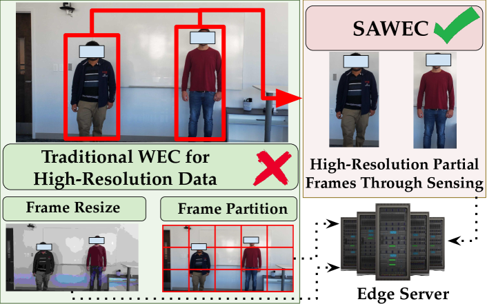
To address the above core issues, we propose Sensing-Assisted Wireless Edge Computing (SAWEC). As depicted in Figure 3, SAWEC offloads to the edge server only the relevant portions of the frames – thus decreasing data rate requirements with respect to traditional edge computing approaches, without losing any image resolution. In stark opposition with existing art that compresses or partitions frames [18, 19], SAWEC leverages wireless sensing to localize and track environmental changes such as the movements of humans or other objects. This way, instead of offloading the whole frame, SAWEC only offloads the part of the frame where motion is detected, hereafter referred to as region of interest (ROI). Since wireless sensing-based localization can operate concurrently with wireless communications, SAWEC does not require any dedicated infrastructure as it leverages the channel frequency response (CFR) computed through the channel estimation procedure which is routinely required by any wireless communication standard such as Wi-Fi (IEEE 802.11). Even though it would be possible to take similar approaches with event-based cameras[20] or software-only-vision[21], the approach in SAWEC is much simpler which also does not need any dedicated additional device.
Summary of Novel Contributions
We present SAWEC, a novel paradigm that performs wireless edge computing by leveraging wireless sensing integrated with the communication process (Section III). SAWEC optimizes the edge offloading process by localizing and tracking environmental changes that eventually determine the ROI to offload to the edge server instead of the whole frame. This way, SAWEC optimizes the transmission latency and channel utilization while improving the DNN performance;
A key challenge is that since existing IEEE 802.11ac (Wi-Fi 5)-based Wi-Fi localization systems operate with up to 80 MHz bandwidth, they incur in relatively low range resolution. To have better localization granularity, in Section IV we present a custom-tailored localization and tracking approach based on density-based spatial clustering of applications with noise (DBSCAN), explained in Section IV-C. In addition, we propose a framework to project the estimated localization information in a 360° video frame for detecting the ROI as explained in Section IV-D;
We implemented and validated the SAWEC through several experiments in multiple propagation environments, i.e., an anechoic chamber and a hall room (Section V). In each of the environments, we performed an extensive data collection campaign with six different setups involving two human subjects (IRB approval is available upon request). In Section VI, we compare SAWEC with state-of-the-art work YolactACOS [22] and EdgeDuet [19] and demonstrate that SAWEC reduces the channel occupation and end-to-end latency by 93.81% and 96.19% respectively while improving the instance segmentation performance by 46.98%. We share the whole dataset and code repository for reproducibility and research purposes at https://github.com/kfoysalhaque/SAWEC.
II Background and Related Work
Wireless edge computing (WEC) has gained significant traction over the last few years [23, 24]. Prior work has focused on reducing the end-to-end latency as well as the channel occupation by employing DNN partitioning [25], frame partitioning [19] and full task offloading [26]. While frame downsizing and frame compression approaches [18] can effectively decrease energy consumption and channel usage, they can hardly be applied in VR applications with 8K resolution and higher.
To show this point, we have performed an experiment on facial expression detection with different image downsize ratios ranging from 1 (image resolution 10241024) to 1/16 (image resolution 6464) and image compression ratios ranging from 1 to 1/32. Note that VR applications would need much higher resolution frames than 10241024 [27]. We first create a high-resolution facial emotion dataset with 10241024 image resolution containing 8000 augmented images from six subjects categorized into six facial emotion classes: angry, disgust happy, sad, surprise, and neutral. We implemented an 8-layer convolutional neural network (CNN) structure inspired by VGG-16 [28] as the baseline.
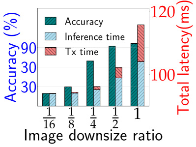
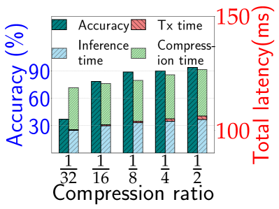
Figure 2 presents the performance of facial expression detection with various image downsize ratios i.e., various image resolutions and compression ratios. It demonstrates that the performance degrades up to 79% and 62% if the images are downsized by less than 1/2 and compressed by less than 1/8 respectively. We point out that downsizing the frame by 1/2 or less, drastically hampers the DNN performance of a basic task like expression detection. Notice that for more complex tasks such as instance segmentation, there are no available models to execute 10K resolution images directly. This is due to the unavailability of trained models and datasets for training at such a higher resolution and inherent computational complexity. To fit a 10K image, the frames need to be downsized at least by 1/16 times which would surely fail to maintain the performance requirements.
Some existing work that is complementary to ours has used wireless sensing for vision-oriented approaches in multi-modal [29], cross-modal [30], and transfer learning settings [31]. For example, Xie et al. [32] utilizes a single off-the-shelf time of arrival (ToA) depth camera to generate high-resolution maps in a noisy and dark environment. However, to the best of our knowledge, none of the earlier work has proposed wireless sensing to assist edge offloading.
III System Overview
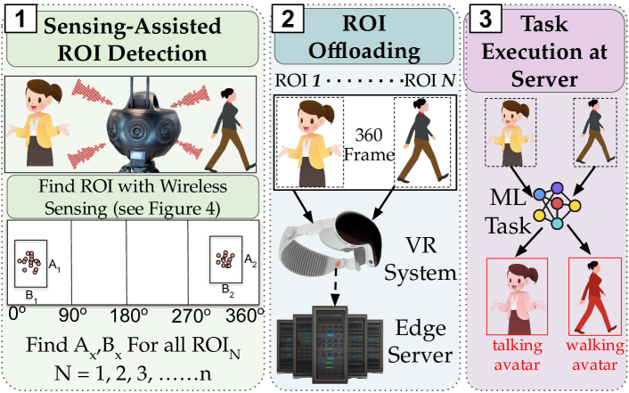
SAWEC empowers modern mobile devices featuring 360° cameras with wireless sensing functionalities that identify the ROI inside each captured video frame before transmitting it to the edge. SAWEC consists of three main blocks, as summarized in Figure 3: (1) sensing-assisted ROI detection, (2) ROI offloading, and (3) task execution at the edge server.
(1) Sensing-assisted ROI Detection: The ROI detection is based on the context information obtained through wireless sensing. Specifically, we leverage the CFR estimated by the wireless network interface card (NIC) to detect the dynamics in the environment. SAWEC synchronizes channel measurements with the video frames through their timestamps, and obtains an estimate of the locations of the targets in the environment by processing the CFR through multi-path parameter estimation algorithms. A tracking algorithm allows detecting the ROI, being the area where changes were detected. Note that the CFR estimation is performed by leveraging the training field in received packets. Therefore, the system requires at least another device in the network. Hereafter we will consider that two (the minimum) devices are involved and will refer to the sensing NIC as the NIC where the CFR estimation is performed and to the transmitter NIC as the one transmitting wireless signals for triggering CFR estimation.
(2) ROI Offloading: The ROI offloading block is in charge of selecting the portion of the high-resolution frame to be offloaded to the edge server based on the context information gained through wireless sensing. By transmitting only the ROIs instead of the entire frame, SAWEC reduces the wireless channel occupation and the transmission latency.
(3) Task Execution at Edge Server: The edge server receives the ROIs from the camera and uses them as input for the DNN task, thus obtaining two main advantages with respect to traditional approaches. First, SAWEC executes the DNN on high-resolution ROIs instead of on their compressed and/or reshaped versions. Moreover, processing the ROIs instead of the whole (bigger) frames reduces both the training and inference time. Combined with the reduced transmission latency mentioned above, SAWEC allows reducing the end-to-end transmission and computing time.
IV Sensing-Aided ROI Detection
The CFR-based localization has been implemented by adapting the super-resolution multi-path parameter estimation algorithm MD-Track [33]. Hence, for tracking, we implemented a custom-tailored approach based on density-based spatial clustering of applications with noise (DBSCAN).
IV-A Wi-Fi Channel Model
We consider a system where is the number of receiving antennas and indicates the receiving antenna index. Being the main carrier frequency, the orthogonal frequency-division multiplexing (OFDM) sub-channel spacing and the OFDM symbol time, the CFR for sub-channel , estimated at receiver antenna and time , , is modeled as [34]
| (1) |
where represents the multi-path components associated with the wireless signal propagation, each of which is characterized by an attenuation and a ToA (also referred to as propagation delay). Each multi-path component is associated with a static or moving object in the environment that acts as a reflector, diffractor, or scatterer for the wireless signal propagating from the transmitter to the receiver. The propagation delay is associated with the position of the -th object in the environment and the collecting antenna. Each multi-path component is collected by each antenna in subsequent time instants that depend on the angle of arrival (AoA) . Indicating with the antenna-dependent contribution to the length of the -th component, the ToA is obtained as
| (2) |
where is the speed of light. Considering a linear array with antennas spaced apart by and using the left antenna as the reference, , where the AoA is measured clockwise starting from the direction perpendicular to the antenna array.
IV-B Super Resolution Multi-Path Parameter Estimation
To ease the proper estimation of the AoA, the receiver antennas are usually spaced apart by where is the wavelength of the carrier signal. In turn, and the contribution of to can be written as . The parameters of the multi-path components in , i.e., , , can be estimated by computing the inverse Fourier transformation of the CFR in Eq. (1) over the subcarrier and receiver antenna dimensions, respectively. However, the resolution of the Fourier transform approach is constrained by the CFR diversity in the frequency and spatial domains. Super-resolution algorithms can be used to deal with these limitations and obtain more precise AoA and ToA estimates by leveraging the sparse nature of the wireless channel [35]. The intuition behind super-resolution algorithms is that in case two paths cannot be separated considering one of the parameters, they may be separable in the other dimension. For example, in the case of two paths closely spaced in time, they may be characterized by different AoAs and, in turn, can be identified as two separate contributions. Hence, the resolution can be improved by jointly estimating all the parameters of each multi-path component. In this work, we use the iterative mD-Track algorithm for this purpose [33]. Note that we focus on the identification of the AoA and ToA (-dimensional mD-Track) as they are sufficient for providing enough side information for ROI detection.
IV-C AoA and ToA Clustering and Tracking
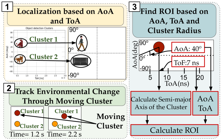
To improve the accuracy of the local pre-processing (frame windowing) before frame transmission, SAWEC uses a number of channel estimated for each frame. Specifically, being the video frame collection rate, measured in frames per second (FPS), and the frequency (in Hz) of CFR collection (and, in turn AoA and ToA estimation), SAWEC set such that the localization for each frame is performed using CFR samples. For example, considering a system with CFR estimation frequency of 200 Hz, and video frame rate of 25 FPS, the AoA and ToA estimation for each frame is performed leveraging CFR samples. The localization proceeds as summarized in Figure 4. At first, the AoA and ToA are estimated for each of the CFR samples related to a video frame. After that, the AoA/ToA pairs are clustered through DBSCAN, removing the outliers associated with noise (step 1). Hence, the centroids are compared with the centroids of the clusters associated with the previous video frame to detect any change in their location (step 2). The information about moving targets is then used in step 3 to obtain the ROI for video frame processing, as detailed in Sections IV-D and IV-E.
IV-D AoA and ToA Projection into the Camera Reference System
For proper selection of the ROI through the sensing side information, the NIC for CFR data collection and the 360° camera have to share the same reference system. This would require: (i) the camera and the sensing NIC to be exactly co-located and, in turn, capture the same field of view, and (ii) the NIC transmitting opportunistic signals to trigger CFR estimation to be placed exactly on the tangent of sensing NIC antenna array, to share the same common zero of AoA reference frame. However, these requirements are hardly achievable from a physical perspective due to the physical location of the devices. In turn, we need to ‘project’ the AoA and ToA estimated through the sensing NIC into the camera reference system. For this, we designed a procedure consisting of the two phases detailed next.
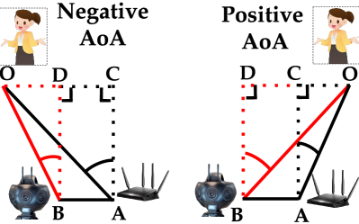
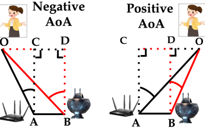
Phase 1 At first, we apply a correction for the slightly different placement of the sensing NIC and the camera. We reasonably assume that they are aligned on two of the three 3D axes (Y and Z axes), and we indicate with and their respective X-axis location. In Figure 5 we provide an overview of the different respective positions of the Wi-Fi sensing NIC, the camera, and the target. Based on these possible situations we designed a corrective algorithm to obtain (AoA in the camera reference system) from (AoA in the sensing NIC reference system). This is obtained by applying trigonometrical theorems as detailed in Algorithm 1. Note that AoA means that the object is on the tangent ( in Figure 5). AoA means that the object is on the right with respect to the tangent, while AoA is associated with an object on the left.
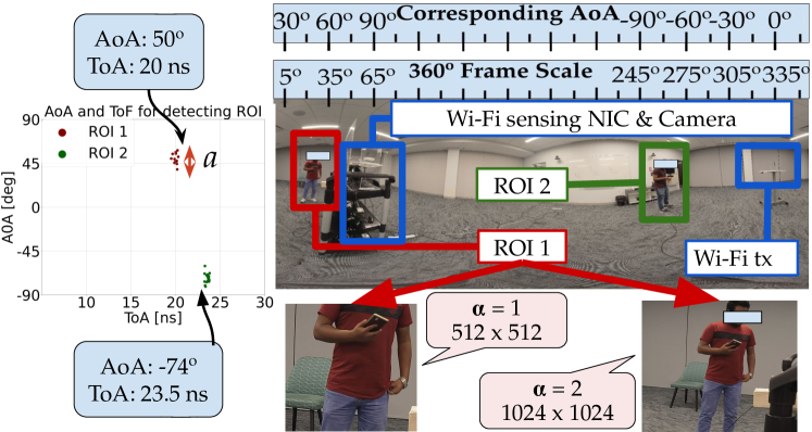
Phase 2 To address the challenge related to the misplacement of the transmitter NIC with respect to the tangent and obtain the same reference for the zero AoA frame, we first set a AoA scale for the frame assigning 0° to the left edge of the camera field of view. Hence, we project the AoA , obtained above, into the AoA value in the new reference system, hereafter referred to as . Specifically, we have where represents the modulo operation and indicates the location of Wi-Fi transmitter in the reference system. An example of the processing is depicted in Figure 6 using real experimental data. For example, identifying ROI 1 corresponds to .
IV-E Estimating the Size of the ROI
For each video frame, we leverage the extension of the detected clusters (see Section IV-C) in the AoA domain to derive the size for the ROIs. Hereafter we will refer to such extension, i.e., the ranges of AoA covered by the cluster, as (measured in degrees). The center of each ROI is set to the center of the cluster and to define its extension we introduce a parameter, hereafter referred to as ROI multiplying factor and indicated with , to account for localization error. Specifically, the ROI extension is set to ° in the AoA domain. For ease of processing, we considered the same extension in the width and height of the ROI. This means that we obtain the number of pixels to be considered for ROI height & width by using where is the width of the entire frame.
As shown in the bottom part of Figure 6, for our specific setup, is too small for having the whole subject in the ROI whereas allows retaining the entire subject.
IV-F SAWEC Processing Time
SAWEC considers CFR samples (with Hz sampling frequency) for estimating AoA and ToA for each video frame (at FPS). Indicating with the processing time for a CFR sample, the total SAWEC processing time is defined by, and SAWEC processing latency is defined by . For example, considering a system with Hz, FPS and ms, SAWEC overall processing time is ms and latency is ms.
V Experimental Setup
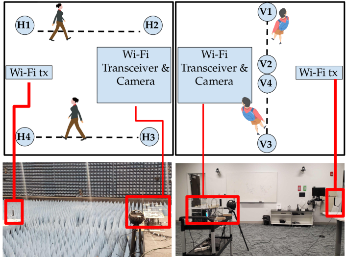
We evaluated SAWEC by implementing the system on commercial devices available on the market. The system comprises an Insta360 Titan 360° camera for video capturing, a Linux machine for video processing, and an IEEE 802.11ax network for communication and wireless sensing (localization and tracking). The system was configured to capture frames at a resolution of 10K with a frame rate of 25 FPS. The IEEE 802.11ax network comprised two commercial-off-the-shelf (COTS) AX200 NIC operating on a 5 GHz Wi-Fi channel with 160MHz of bandwidth. One and two antennas were enabled at the transmitter and sensing devices respectively. At the sensing Wi-Fi NIC, we used PicoScenes for CFR collection [36]. We placed the Wi-Fi receiver and the 360° camera in closed proximity and synchronized the Wi-Fi localization and camera systems by using their internal reference clock. The Wi-Fi transmitter was placed on the opposite side to properly irradiate the environment and obtain valuable information for sensing. We considered two different propagation environments for the evaluation: (i) an entrance hall and (ii) an anechoic chamber. While the entrance hall allows evaluating the performance of SAWEC in a real-world environment, the anechoic chamber provides the best-case scenario evaluation as the multi-path effect is reduced. Note that although our experimental evaluation considers the Wi-Fi 6 (IEEE 802.11ax) standard, the proposed system and the related analysis are general and can be applied to wireless standards operating with multiple-input, multiple-output (MIMO).
The experimental setup along with the evaluation scenarios are presented in Figure 7. We performed six different tests in each of the environments: a single person walking between (i) H1 to H2 (ii) H3 and H4 (iii) V1 and V2 (iv) V3 and V4, and two persons walking simultaneously between (v) H1 & H2 and H3 & H4 and (vi) V1 & V2 and V2 & V3. Data were collected for three minutes for each of the tests. The tests on the anechoic chamber and the entrance hall were performed on different days, at different times of the day and with different orientations of the systems. Due to physical constraints, the 360° camera is negatively shifted along the X-axis by 1m in the hall room and 0.5m in the anechoic chamber whereas the spacing between the Wi-Fi transceiver and the CFR injector is 3m for both the environments.
VI Performance Evaluation
We assessed the performance of SAWEC by performing an extensive experimental data collection campaign and evaluating three main metrics: (i) accuracy of the DNN task; (ii) wireless channel occupation; and (iii) end-to-end latency. In the following results, the metrics have been averaged over all the frames captured in both the anechoic chamber and the entrance hall. For a baseline comparison, we evaluate SAWEC against two state-of-the-art (SOTA) algorithms: (i) YolactACOS adaptive edge assisted segmentation [22], (ii) EdgeDuet context-aware data partition-based WEC [19]. YolactACOS selectively offloads computationally intensive tasks. On the other hand, EdgeDuet adopts a partition-based approach by offloading the segmentation tasks of small objects.
For the DNN task we chose instance segmentation as it is one of the widely used benchmarking tasks for edge computing. We executed the DNN training and inference in a Linux machine with 12th Generation Intel(R) Core(TM) i7-12700K central processing unit (CPU) with 64 GB of random access memory (RAM) (memory speed: 4800 mega-transfer/second) and a graphics processing unit (GPU) (RTX A4000) of 16 GB memory with computational capability of 7.5. We considered the performance metric to assess instance segmentation performance. This metric represents the mean average precision across intersection over union (IoU) thresholds spanning from 50% to 95% where IoU measures the overlap between predicted and ground truth regions. The communication between the Wi-Fi-aided camera system and the edge computer is obtained through an IEEE 802.11ax MIMO link. The frames were transmitted from the camera to the edge server through a Wi-Fi link from an Intel AX200 NIC (2 antennas) at the camera and an Asus-RT-AX86u access point (AP) (4 antennas) at the edge server. The average link speed was MB/s. The edge server was connected to the AP through an Ethernet link. The camera’s NIC and the AP were in the line of sight at a distance of m from each other.
VI-A Performance for Different ROI Multiplying Factors
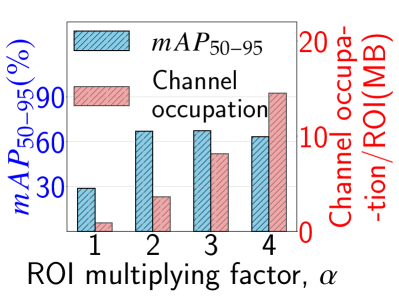
In Figure 8a we present the segmentation accuracy of the YOLOv8m model [15] when varying from to . The results show that with , is % meaning that the segmentation accuracy is very poor. This is due to the fact that the ROI is too small to contain the pixels of the entire subject, as depicted in Figure 6. Starting from the ROI is sufficiently large to cover the subject (see Figure 6) and, in turn, the reaches %. The performance slightly decreases when as the image will contain more objects to be segmented. On the other hand, the channel occupation keeps increasing when increasing as this requires transmitting an increasing number of pixels. We have selected for the following evaluation as a tradeoff between the segmentation performance and channel occupation.
VI-B Performance for Different Edge Computing Approaches
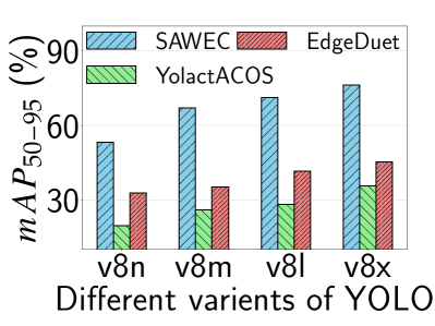
We analyze the performance of frame segmentation with the three different edge computing approaches mentioned before: SAWEC, YolactACOS, and EdgeDuet. We consider four variants of SOTA YOLOv8 segmentation model [15]: YOLOv8x, YOLOv8l, YOLOv8m, and YOLOv8n. According to the benchmark [15], YOLOv8x is the highest-performing model with the highest inference latency whereas YOLOv8n is the lowest-performing model with the lowest inference latency. The average performance of the segmentation task on original (K) frames considering both environments is presented in Figure 8b. Similar to the benchmark in [15], YOLOv8x performs best with all the approaches (SAWEC, YolactACOS, and EdgeDuet) whereas YOLOv8n performs the worst. Importantly, SAWEC surpasses the benchmark of with YOLOv8x on COCO dataset [17] by a large margin by achieving an of whereas YolactACOS and EdgeDuet achieved only and respectively. This is because with YolactACOS the K image is downsized times by the model itself to fit to the model input dimension of . This heavy downsizing hampers the performance severely. For the EdgeDuet, the performance hampers as objects fall into multiple tiles which are processed separately and because of the small objects not being detected all the time. On the other hand, with SAWEC at , the average dimension of the detected ROIs is which needs to be downsized by only 0.667 times and it retains the higher quality of the images leading to a better performance.
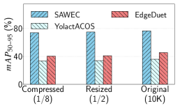
We also perform the comparative performance analysis of SAWEC, YolactACOS, and EdgeDuet when the frames for all the approaches are downsized and compressed to and respectively (tolerable ratio as observed from the expression detection test). Figure 9a presents the of the three approaches with original (10K), resized (1/2), and compressed (1/8) versions of the video frames. Similar to the observation of the preliminary facial expression detection test, the performances for all the approaches degrade slightly due to the rational image resizing and compression. This might give SAWEC a further performance boost in terms of transmission latency and channel occupation. However, for a more delicate task like avatar and expression reconstruction, even downsizing and compressing by the ratio of only and respectively might affect the performance dramatically.
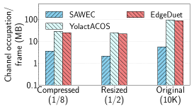
VI-C Analysis of Channel Occupation Usage
Analyzing the per-frame channel occupation for all the methods – SAWEC, YolactACOS, and EdgeDuet – is paramount, considering that the radio spectrum is a pivotal and limited resource for wireless networks. The average per-frame channel occupation of SAWEC, YolactACOS, and EdgeDuet with three different frame sizes – original (no resize and no compression), resized (), and compressed () – is depicted in Figure 9b. The results show that for original frames, SAWEC reduces the channel occupation by , and respectively in comparison to YolactACOS and EdgeDuet. To elaborate further, on average, the size of an original frame is MB whereas the average channel occupation required by SAWEC, YolactACOS, and EdgeDuet are MB, MB and MB per frame respectively. Note that, the number of ROI is more than one for the tests with multiple persons moving simultaneously in the environment. In fact, the channel occupation of SAWEC might increase a little bit depending on a higher number of moving subjects in the environments. However, to have an idea, even after having a total of ROIs (with ) per single K frame adds up to only MB reducing the channel occupation by .
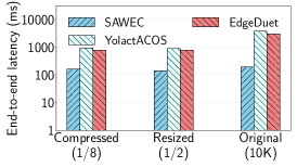
VI-D End-to-End Latency Analysis
End-to-end latency is one of the critical factors for time-critical edge computing tasks including a wide range of VR applications. We analyze the end-to-end latency of SAWEC by comparing it with YolactACOS, and EdgeDuet for different frame types as presented in Figure 9c. The average end-to-end latency of SAWEC is ms, ms, and ms for original, resized (), and compressed () frames respectively, which is much lower than the other two approaches. With 10K resolution, SAWEC improves the latency by and in comparison to the YolactACOS and EdgeDuet respectively. To have a better understanding, end-to-end latency for the original 10K frames is broken down in Table I. We can see that the transmission (TX) time and input/output (I/O) time of the YolactACOS is around times and times higher in comparison to the corresponding values of SAWEC. This is due to the higher channel occupation of the YolactACOS in comparison to SAWEC. On the other hand, I/O time for the EdgeDuet is similar to that of SAWEC as the whole frame is divided into smaller tiles. However, this does not improve the TX time which is around 15 times higher than SAWEC.
Note that the effectiveness of ROI detection is contingent upon wireless localization and tracking. While SAWEC is well-suited for typical day-to-day scenarios, its performance is anticipated to diminish in highly dynamic environments. Moreover, determining the number of moving subjects that are tolerated by SAWEC before the performance degrades is a challenging problem, as it depends on (i) distance among the subjects, (ii) the speed with which subjects are moving, (iii) localization algorithm and (iv) the number of antennas that we use for localization. We believe these aspects deserve a separate investigation. Future research efforts will include improving the SAWEC performance in highly dynamic scenarios by enhancing the localization resolution.
|
|
|
|
|
|
|||||||||||||
|---|---|---|---|---|---|---|---|---|---|---|---|---|---|---|---|---|---|---|
| SAWEC | 79.44 | 15.75 | 18.43 | 75.0 | 0 | 188.62 | ||||||||||||
| YolactACOS | 1311 | 528.46 | 19.79 | 0 | 1779.34 | 3638.59 | ||||||||||||
| EdgeDuet | 1221.62 | 16.73 | 18.56 | 0 | 1667.18 | 2920.91 |
VII Conclusions
In this paper, we proposed a new paradigm for wireless edge computing called SAWEC. Our new approach leverages Wi-Fi-based localization and tracking to support high resource-consuming computer vision tasks by obtaining the location of ROI based on the environment dynamics. This information allows offloading to the edge server only the detected ROI instead of the entire frame, thus reducing airtime overhead and overall latency. The AoA and ToA estimated from the Wi-Fi CFR are used to locate the ROIs in the video frames. We have assessed the effectiveness of SAWEC through extensive data collection campaigns in two different environments: a hall room and, an anechoic chamber, each having six different test experiments. Our proposed approach reduces the overall end-to-end latency by and respectively while achieving and net improvement in comparison to the SOTA WEC approach – YolactACOS, and EdgeDuet. We evaluated the performance of SAWEC using two antennas for the Wi-Fi localization system to prove the new concept. Future research avenues include the localization performance improvement by increasing the number of antennas.
Acknowledgements
We sincerely thank our shepherd Tristan Braud and the anonymous reviewers, who have significantly contributed to improve the quality of the final manuscript. This work has been funded in part by the National Science Foundation under grants CNS-2134973, CNS-2120447, and ECCS-2229472, by the Air Force Office of Scientific Research under contract number FA9550-23-1-0261 and by the Office of Naval Research under award number N00014-23-1-2221. The work was also partially supported by the European Union under the Italian National Recovery and Resilience Plan (NRRP) of NextGenerationEU, partnership on “Telecommunications of the Future” (PE00000001 - program “RESTART”), and by the Fulbright Schuman Program.
References
- [1] Declan McGlynn, Rolling Stones., “Music and the Metaverse: Are we on the brink of a virtual artist revolution?” https://tinyurl.com/39ed34dd, 2022.
- [2] B. Kye, N. Han, E. Kim, Y. Park, and S. Jo, “Educational Applications of Metaverse: Possibilities and Limitations,” Journal of Educational Evaluation for Health Professions, vol. 18, 2021.
- [3] VentureBeat.com, “Medicine and the Metaverse: New Tech Allows Doctors to Travel Inside of Your Body,” https://tinyurl.com/243a4jnm, 2022.
- [4] A. Somrak, I. Humar, M. S. Hossain, M. F. Alhamid, M. A. Hossain, and J. Guna, “Estimating VR Sickness and User Experience Using Different HMD Technologies: An Evaluation Study,” Future Generation Computer Systems, vol. 94, pp. 302–316, 2019.
- [5] J. Soni, “Apple vision pro vs. meta quest 3: The next generation of vr,” Jan 2024. [Online]. Available: https://www.dexerto.com/tech/apple-vision-pro-vs-meta-quest-3-2168054/
- [6] X. Wu, D. Sahoo, and S. C. Hoi, “Recent Advances in Deep Learning for Object Detection,” Neurocomputing, vol. 396, pp. 39–64, 2020.
- [7] Y. Mo, Y. Wu, X. Yang, F. Liu, and Y. Liao, “Review the State-of-the-art Technologies of Semantic Segmentation Based on Deep Learning,” Neurocomputing, vol. 493, pp. 626–646, 2022.
- [8] F. Tao and Q. Qi, “Make More Digital Twins,” Nature, vol. 573, no. 7775, pp. 490–491, 2019.
- [9] Tomislav Bezmalinovic, “Meta Quest 2: 120-Hertz Mode Becomes a Standard Feature,” https://mixed-news.com/en/meta-quest-2-120-hertz-mode-becomes-a-standard-feature/, 2023.
- [10] Y. Matsubara, D. Callegaro, S. Singh, M. Levorato, and F. Restuccia, “BottleFit: Learning Compressed Representations in Deep Neural Networks for Effective and Efficient Split Computing,” in Proc. of IEEE WoWMoM, 2022.
- [11] M. Sandler, A. Howard, M. Zhu, A. Zhmoginov, and L.-C. Chen, “MobileNetV2: Inverted Residuals and Linear Bottlenecks,” in Proceedings of the IEEE Conference on Computer Vision and Pattern Recognition, 2018, pp. 4510–4520.
- [12] M. Tan, B. Chen, R. Pang, V. Vasudevan, M. Sandler, A. Howard, and Q. V. Le, “MnasNet: Platform-Aware Neural Architecture Search for Mobile,” in Proceedings of the IEEE Conf. on Computer Vision and Pattern Recognition, 2019, pp. 2820–2828.
- [13] K. He, X. Zhang, S. Ren, and J. Sun, “Deep Residual Learning for Image Recognition,” in Proceedings of the IEEE Conference on Computer Vision and Pattern Recognition (CVPR), 2016, pp. 770–778.
- [14] Institute of Electrical and Electronics Engineers (IEEE), “IEEE Standard for Information Technology–Telecommunications and Information Exchange between Systems Local and Metropolitan Area Networks–Specific Requirements Part 11: Wireless LAN Medium Access Control (MAC) and Physical Layer (PHY) Specifications Amendment 1: Enhancements for High-Efficiency WLAN,” IEEE Std 802.11ax-2021 Amendment to IEEE Std 802.11-2020, pp. 1–767, 2021.
- [15] G. Jocher, A. Chaurasia, and J. Qiu, “YOLO by Ultralytics,” Jan. 2023. [Online]. Available: https://github.com/ultralytics/ultralytics
- [16] A. Kirillov, E. Mintun, N. Ravi, H. Mao, C. Rolland, L. Gustafson, T. Xiao, S. Whitehead, A. C. Berg, W.-Y. Lo et al., “Segment Anything,” arXiv preprint arXiv:2304.02643, 2023.
- [17] T.-Y. Lin, M. Maire, S. Belongie, J. Hays, P. Perona, D. Ramanan, P. Dollár, and C. L. Zitnick, “Microsoft coco: Common objects in context,” in Proc. of ECCV. Springer, 2014, pp. 740–755.
- [18] W. Jiang, Z. Teng, M. Li, and L. P. Qian, “Energy-Efficient Data Compression and Resource Allocation for Edge Assisted IoT Networks,” in Proc.of IEEE/CIC ICCC. IEEE, 2023, pp. 1–6.
- [19] Z. Yang, X. Wang, J. Wu, Y. Zhao, Q. Ma, X. Miao, L. Zhang, and Z. Zhou, “Edgeduet: Tiling Small Object Detection for Edge Assisted Autonomous Mobile Vision,” IEEE/ACM Transactions on Networking, 2022.
- [20] C. Iaboni, H. Patel, D. Lobo, J.-W. Choi, and P. Abichandani, “Event Camera based Real-time Detection and Tracking of Indoor Ground Robots,” IEEE Access, vol. 9, pp. 166 588–166 602, 2021.
- [21] S. D. Uhlrich, A. Falisse, Ł. Kidziński, J. Muccini, M. Ko, A. S. Chaudhari, J. L. Hicks, and S. L. Delp, “OpenCap: Human Movement Dynamics from Smartphone Videos,” PLoS computational biology, vol. 19, no. 10, p. e1011462, 2023.
- [22] Y. Xie, Y. Guo, Z. Mi, Y. Yang, and M. S. Obaidat, “Edge-Assisted Real-Time Instance Segmentation for Resource-Limited IoT Devices,” IEEE Internet of Things Journal, vol. 10, no. 1, pp. 473–485, 2022.
- [23] A. Islam, A. Debnath, M. Ghose, and S. Chakraborty, “A Survey on Task Offloading in Multi-access Edge Computing,” Journal of Systems Architecture, vol. 118, p. 102225, 2021.
- [24] B. Wang, C. Wang, W. Huang, Y. Song, and X. Qin, “A Survey and Taxonomy on Task Offloading for Edge-Cloud Computing,” IEEE Access, vol. 8, pp. 186 080–186 101, 2020.
- [25] S. Laskaridis, S. I. Venieris, M. Almeida, I. Leontiadis, and N. D. Lane, “SPINN: Synergistic Progressive Inference of Neural Networks Over Device and Cloud,” in Proceedings of the 26th annual international conference on mobile computing and networking, 2020, pp. 1–15.
- [26] R. Xu, C.-l. Zhang, P. Wang, J. Lee, S. Mitra, S. Chaterji, Y. Li, and S. Bagchi, “ApproxDet: Content and Contention-Aware Approximate Object Detection for Mobiles,” in Proceedings of the 18th Conference on Embedded Networked Sensor Systems, 2020, pp. 449–462.
- [27] Varjo, “VIVE Focus 3 VR Headset for Metaverse Solutions,” https://www.vive.com/us/product/vive-focus3/overview/, 2023.
- [28] K. Simonyan and A. Zisserman, “Very Deep Convolutional Networks for Large-Scale Image Recognition,” arXiv preprint arXiv:1409.1556, 2014.
- [29] Y. Zhao, J. Xu, J. Wu, J. Hao, and H. Qian, “Enhancing Camera-based Multimodal Indoor Localization with Device-Free Movement Measurement using WiFi,” IEEE Internet of Things Journal, vol. 7, no. 2, pp. 1024–1038, 2019.
- [30] J. Yang, Y. Zhou, H. Huang, H. Zou, and L. Xie, “MetaFi: Device-Free Pose Estimation via Commodity WiFi for Metaverse Avatar Simulation,” arXiv preprint arXiv:2208.10414, 2022.
- [31] J. Geng, D. Huang, and F. De la Torre, “DensePose From WiFi,” arXiv preprint arXiv:2301.00250, 2022.
- [32] Z. Xie, X. Ouyang, L. Pan, W. Lu, G. Xing, and X. Liu, “Mozart: A Mobile ToF System for Sensing in the Dark through Phase Manipulation,” in Proceedings of the 21st Annual International Conference on Mobile Systems, Applications and Services, 2023, pp. 163–176.
- [33] Y. Xie, J. Xiong, M. Li, and K. Jamieson, “MD-Track: Leveraging Multi-Dimensionality for Passive Indoor Wi-Fi Tracking,” in Proc. of ACM MobiCom, 2019.
- [34] A. Goldsmith, Wireless Communications, Cambridge, Ed. Cambridge Univ. Press, 2005.
- [35] F. Meneghello, A. Blanco, A. Cusano, J. Widmer, and M. Rossi, “Wi-Fi Multi-Path Parameter Estimation for Sub-7 GHz Sensing: A Comparative Study,” in Proc. of IEEE WiMob, 2023.
- [36] Z. Jiang, T. H. Luan, X. Ren, D. Lv, H. Hao, J. Wang, K. Zhao, W. Xi, Y. Xu, and R. Li, “Eliminating the Barriers: Demystifying Wi-Fi Baseband Design and Introducing the Picoscenes Wi-Fi Sensing Platform,” IEEE Internet of Things Journal, vol. 9, no. 6, pp. 4476–4496, 2021.