Leveraging IRS Induced Time Delay for Enhanced Physical Layer Security in VLC Systems
Abstract
Indoor visible light communication (VLC) is considered secure against attackers outside the confined area where the light propagates, but it is still susceptible to interception from inside the coverage area. A new technology, intelligent reflecting surfaces (IRS), has been recently introduced, offering a way to enhance physical layer security (PLS). Most research on IRS-assisted VLC assumes the same time of arrival from all reflecting elements and overlooks the effect of time delay and the associated intersymbol interference. This paper tackles, for the first time, the effect of time delay on the secrecy rate in VLC systems. Our results show that, at a fixed light-emitting diode (LED) power of 3W, the secrecy rate can be enhanced by up to 253% at random positions for the legitimate user when the eavesdropper is located within a 1-meter radius of the LED. Our results also show that careful allocation of the IRS elements can lead to enhanced PLS even when the eavesdropper has a more favourable position and, thus, a better channel gain than the legitimate user.
Index Terms:
Visible light communication, intelligent reflecting surfaces, time delay, intersymbol interference, physical layer security, secrecy rate.I Introduction
Wireless mobile communications have become an integral part of our daily lives. The number of internet users worldwide increased from 3.9 billion in 2018 to 5.3 billion in 2023, representing a CAGR of 6%, which caused the radio frequency (RF) spectrum to become overcrowded, leading to a need for innovative solutions [1]. Visible light communication (VLC) emerges as an alternative solution, operating in the spectrum between 400 and 790 THz, and offering many advantages, including multi-Gbps wireless transmission, high data density, interference mitigation, beam steering, easy integration with lighting functionalities, and cost-effectiveness [2, 3, 4]. VLC systems have the ability to utilise advanced beamforming and jamming techniques which are also used in RF communications for improving the physical layer security (PLS). Moreover, the unique characteristics of light, such as its inability to penetrate opaque objects, provide a clear security advantage compared to RF communication [5].
Intelligent reflecting surfaces (IRS), an innovative technology consisting of passive elements that can reflect and redirect waves, provides a new way to enhance PLS. In the literature, the primary focus of IRS-assisted VLC systems has been on maximising sum rate [6, 7], blockage problem migitation [9, 8], and enhancing PLS[10, 11, 12, 13]. In optical wireless communications (OWC), including VLC, small-scale fading is reduced by the spatial averaging properties of photodiodes (PD). However, the issue of intersymbol interference (ISI) persists due to differential delays encountered in multipath signal combinations, resulting in a non-flat channel frequency response [14]. In most OWC studies that feature IRS, the delay introduced by the elements is not considered, with an assumption of simultaneous arrival for all multipath signals [6, 7, 9, 10, 11, 12]. In [15], an advanced tapped-delay line channel model for IRS-enhanced VLC systems is introduced, considering various scenarios and assumptions. This model enables the characterisation of time delay dispersion resulting from IRS-reflected paths. In [16], the impact of IRS-induced time delay on the VLC channel characteristics in the frequency domain is investigated, showing that an IRS array can consistently improve the performance of narrowband VLC systems.
In this letter, we present a novel method of using time delay and both constructive and destructive ISI to improve the performance of PLS in direct current optical frequency division multiplexing (DCO-OFDM) IRS-assisted VLC systems. We propose an IRS element allocation scheme based on the genetic algorithm (GA) to maximise the rate at the legitimate user while minimising it at the eavsdropper, resulting in a secrecy rate enhancement. To the best of our knowledge, this is the first use of such a method in this field.
II System Model
In this work, we consider the downlink transmission in an IRS-assisted VLC system based on DCO-OFDM, as shown in Fig. 1. The system consists of a single light-emitting diode (LED) located in the centre of the room and configured with two users: one legitimate user, referred to as Bob, and one eavesdropping user, referred to as Eve, both situated at random positions within the room.
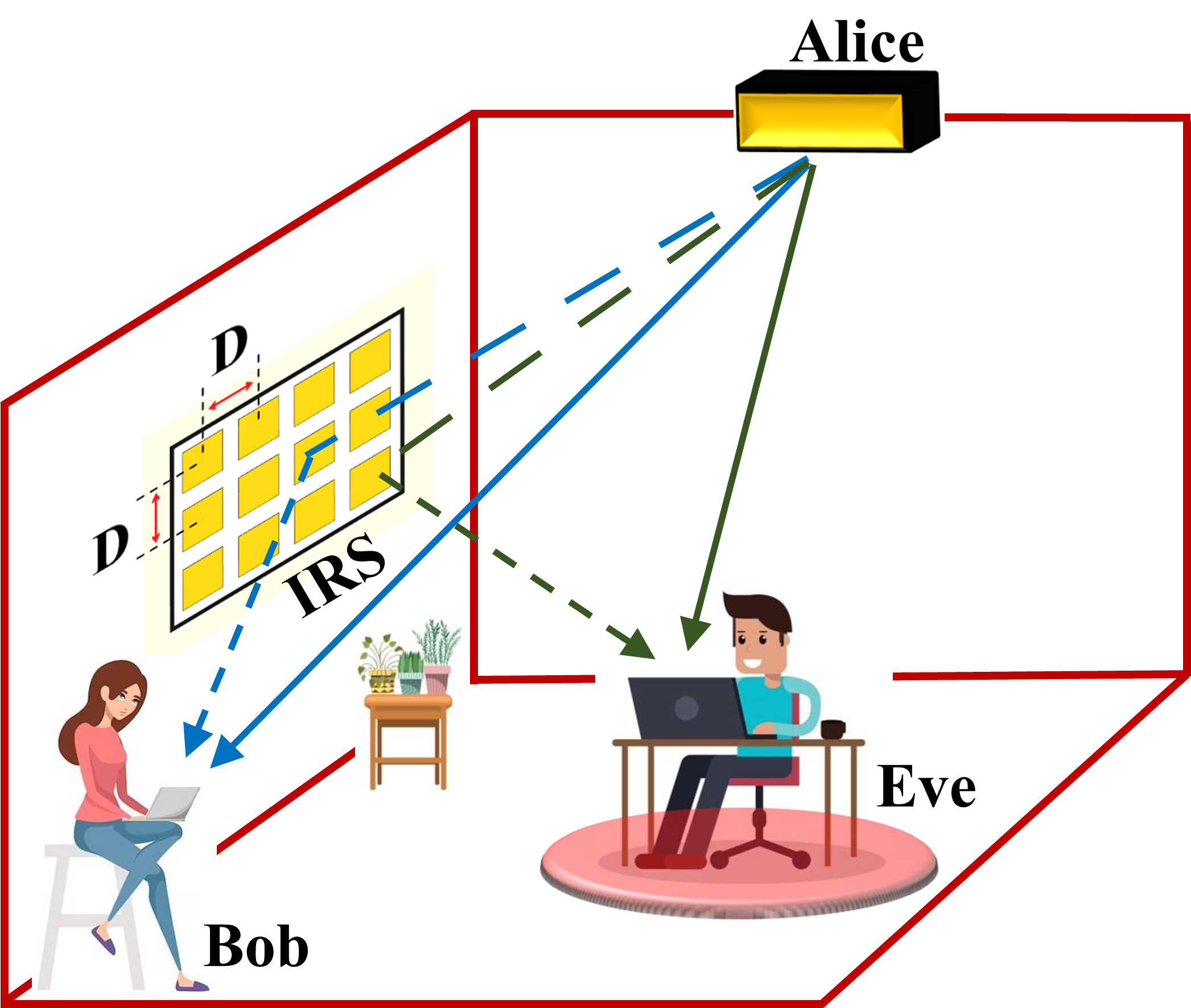
Additionally, there are reflecting elements fixed on one room wall with a separation distance between the elements. In IRS-assisted VLC, the transmitted signal reaches the receiver via two paths: line-of-sight (LoS) and non-line-of-sight (NLoS). These paths are discussed in detail in the following subsections.
II-A LoS Channel
The direct signal received at the PD of the users in an IRS-assisted VLC system is important for system performance. In our model, the LoS channel gain for a generic k-th user, which we denote as , follows the Lambertian model and can be represented as:
| (1) |
where represents the physical area of the PD, denotes the Euclidean distance between the LED and PD for the k-th user, and and are the angles of incidence and irradiance between the LED and PD normal, respectively. The terms and represent the optical filter transmission and concentrator gain of the PD, and signifies the Lambertian order, which is given by:
| (2) |
Eve receives and Bob receives .
II-B NLoS Channel
In calculating the NLoS channel gain, we primarily focus on the elements array. This array consists of a size denoted by . Here, represents the number of IRS elements in each row, while signifies the number of columns of IRS elements. In RF systems, IRS arrays are generally utilised to manipulate the phase of reflected signals, enhancing the efficiency of signal propagation. However, in VLC systems, which mainly handle signal intensity rather than phase, element arrays cannot control the phase of signals. Instead, in a VLC system with an array of elements, the orientation of elements is crucial for directing the light toward the users accurately. This is managed by adjusting two rotational angles: (a) the yaw angle , which controls the horizontal adjustment of the elements around a vertical axis, and (b) the roll angle , which controls the vertical adjustment of the elements around a horizontal axis. These angular adjustments enable the system to reflect the light signals toward the intended receivers precisely. Such a strategy can improve signal quality at the receiver end, especially in NLoS conditions. NLoS gain can be computed using an additive model. The specular reflected gain between the -th user and the -th IRS mirror is expressed as follows[17]:
| (3) |
where represents the element reflectivity. The terms and represent the Euclidean distances from the LED to the -th reflecting element and from the -th reflecting element to the -th user, respectively. Finally, and refer to the angles of irradiance and incidence relative to the element array path.
In this work, we consider realistic assumptions and account for the time delay in light propagation for both LoS and NLoS scenarios. To accurately represent channel characteristics, we calculated the overall channel impulse response (CIR) using the following equation [16]:
| (4) |
In (4), denotes the unit impulse function. The terms and represent signal propagation delays, and is the speed of light.
The channel frequency response (CFR), which represents the Fourier transform of CIR, is given by [16]:
| (5) |
In (5), the terms and represent the phase shifts at frequency due to the time delays and , associated with the LoS and NLoS components, respectively.
Following the derivation of CFR, we address the signal-to-noise ratio (SNR). As a cardinal metric, the SNR compares the power of the modulated signal to the power of the background noise at the PD and is a direct indicator of the system’s capacity to convey information accurately. The SNR can be written as [18]:
| (6) |
where is the symbol period, represents a uniform power distribution, is the optical power transmitted by the LED, is the channel power gain at frequency , is the PD responsivity. Moreover, the gap value, represented as , quantifies the disparity between theoretical predictions and actual system performance, influenced by factors such as modulation and coding scheme. The modulation scaling factor, expressed as , is pivotal for adjusting the signal amplitude within the operational constraints of the LED, optimizing power usage, and minimizing distortion due to signal clipping. The noise power spectral density is a function of the PD load resistance , the optical power detected by the PD , and the absolute temperature , given by:
| (7) |
where represents Boltzmann’s constant and is the electronic charge.
In our system, we utilise the SNR to calculate the rates of Bob and Eve users. The IRS elements are strategically allocated to enhance Bob’s signal through constructive interference while simultaneously reducing Eve’s signal with destructive interference. This configuration of the IRS elements array is essential in maximising the secrecy rate of the system.
The rate for Bob’s user is given by [16]:
| (8) | ||||
and for Eve’s user by [16]:
| (9) | ||||
A binary vector , where, can only be a 0 or 1. If , it indicates -th IRS elements allocated to the Bob user, while indicates -th IRS elements allocated to Eve’s user. The variables used in (8) and (9) are defined in Table I.
III Problem Formulation
In this study, we investigate the maximisation of secrecy capacity in an IRS-assisted VLC system. To the best of our knowledge, this has not been explored in the open literature with consideration of time delay effects. The secrecy capacity is the difference in data rates between Bob and Eve. To handle the complexity that arises when the number of IRS elements increases, we employ the GA that searches iteratively for the best user-element allocation pattern. We aim to maximise the secrecy capacity , subject to a set of constraints that govern the allocation of the IRS elements and the power distribution across the modulation bandwidth. The optimisation problem can be formulated as follows:
| max | (10) | |||||
| subject to | ||||||
The binary variable indicates whether the -th IRS element is allocated to user (with 1 denoting allocation to Bob and 0 to Eve), ensuring single element can not serve more than one user at a time. The constraint ensures a uniform power distribution over the frequency range.
The detailed expression for the secrecy capacity is presented as:
| (11) |
III-A Optimisation with GA
The GA is considered particularly useful in complex optimisation problems where there are many possible configurations, such as the challenge of allocating elements. GA works by creating a population of potential solutions to an optimisation problem and then improving them iteratively through processes similar to biological evolution. These processes include selection, crossover, and mutation.
III-A1 Algorithm Overview
The key steps of the GA in the context of our problem are as follows:
-
•
Initialisation: Generate an initial population of potential solutions, each encoding an IRS element allocation pattern as a binary string.
-
•
Fitness Evaluation: Assess each solution’s quality based on its ability to maximise the secrecy capacity.
-
•
Selection: Choose the fittest solutions to be parents of the next generation, favouring those with higher secrecy capacities.
-
•
Crossover: Combine pairs of parent solutions to produce offspring, inheriting features from both, which promotes the mixture of beneficial traits.
-
•
Mutation: Introduce random changes to new solutions, maintaining diversity in the population and preventing premature convergence.
-
•
Replacement: Form a new generation of solutions, typically by replacing some of the less fit solutions with the new offspring.
This iterative process continues until a satisfactory solution is found or a predefined number of generations have passed. The GA ability to handle binary decision variables makes it particularly well-suited for problems like ours, where each IRS element can be either allocated to Bob or Eve. By optimising element allocations using GA, we can significantly reduce the complexity of the problem from an exhaustive search, which is computationally intractable, to a more manageable iterative search process. This approach enables the discovery of near-optimal solutions within a practical timeframe, making it a valuable tool for enhancing PLS in IRS-assisted VLC systems. The detail steps for GA are shown in Algorithm 1.
IV Simulation Results
In this section, we discuss the simulation results of an indoor room with dimensions of . The simulation parameters are shown in Table I. The main goal of these simulations is to demonstrate the effects of time delay, which leads to constructive and destructive interference which impacts the achievable secrecy capacity.
| Parameters | Values |
|---|---|
| LED optical power [W] | |
| LED half-power semiangle | |
| PD responsivity [A/W] | |
| PD section area [cm2] | |
| PD FoV | |
| Symbol period [ns] | |
| Absolute temperature [K] | |
| Receiver load resistance [] | |
| IRS reflectivity | |
| Modulation scaling factor | |
| Gap value | |
| IRS array size | |
| Separation distance [cm] |
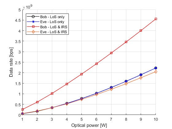
In Fig. 2, a comparison of the data rate against different power levels for Bob and Eve users with and without IRS is shown. The users are located randomly, and the simulation runs for 300 iterations, with averages taken. The results demonstrate how the use of IRS can improve the performance of Bob by allocating elements that cause good delay and create constructive interference. Conversely, it is also shown that elements that cause the worst delay and create destructive interference can degrade the signal power for Eve.
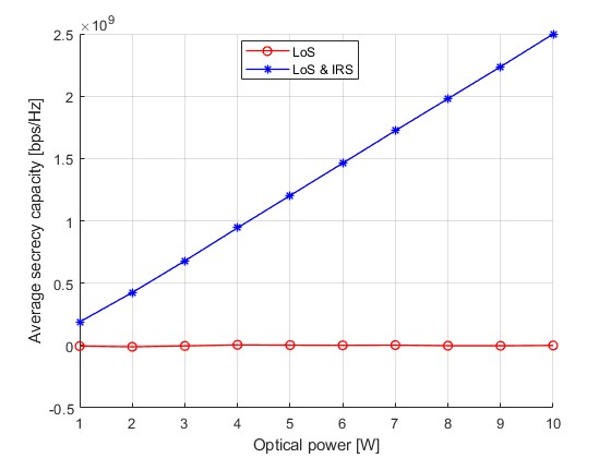
In Fig. 3, we can see how the average secrecy capacity performance is enhanced for the combined LoS and IRS case. It is noted that the secrecy capacity remains at zero for the LoS case since both users are randomly located with equal probability, so the average difference in their rate values remains zero. Moreover, it is noted that the enhancement in Bob’s data rate, evident from Fig. 2, can result in a significant increase in the secrecy capacity even though Eve’s rate is not highly affected.
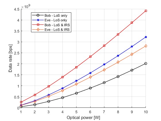
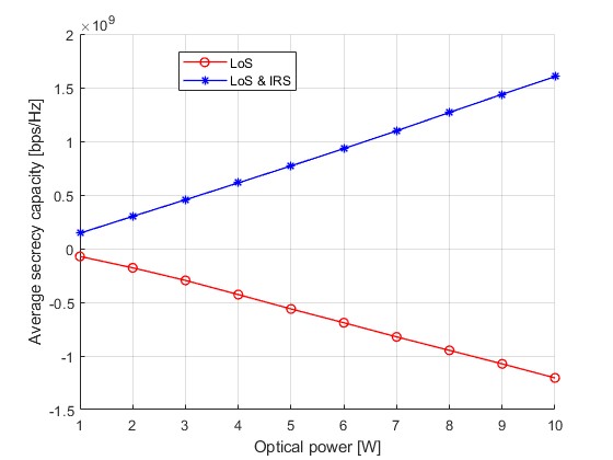
In the following, we investigate the performance when the conditions of Bob and Eve’s locations are not equal. This allows a better demonstration of the effect of the destructive ISI in enhancing the secrecy capacity in certain scenarios. We divide the coverage area into two zones: an inner zone with a radius of 1m within the LED and an outer zone that includes areas further than 1 m from the LED in radius. We assume a worst-case scenario in which Eve is closer to the LED than Bob. The simulation results in Fig. 4 show how time delay and ISI for the case of LoS and IRS can enhance Bob performance and degrade Eve power. It is noted that at 7W optical power, the Bob user rate improved by 59.41%, reducing the Eve user rate by 12.30%. Fig. 5 shows the corresponding secrecy capacity for the worst-case scenario when Eve is closer to the LED. It is noted that secrecy capacity is negative for the LoS case because Eve is located closer to LED.
V Conclusion
This paper presented a novel approach that utilises the time delay aspect in IRS-assisted VLC systems for establishing PLS. Our results showed that a simple GA-based IRS allocation can result in significant secrecy rate enhancement, even when the eavesdropper is closer to the LED than the legitimate user. We believe that further investigations of IRS-induced time delay can open the door for equipping VLC with an even higher security advantage against interception attacks.
References
- [1] Cisco Systems, Inc., “Cisco Annual Internet Report (2018–2023) White Paper,” Cisco Systems, Inc., White Paper, 2023. [Online]. Available: https://www.cisco.com/c/en/us/solutions/collateral/executive-perspectives/annual-internet-report/white-paper-c11-741490.html
- [2] H. Haas, L. Yin, Y. Wang, and C. Chen, “What is LiFi?,” J. Lightwave Technol., vol. 34, no. 6, pp. 1533–1544, Mar. 2016.
- [3] H. Haas, M. S. Islim, C. Chen, and H. Abumarshoud, “An Introduction to Optical Wireless Mobile Communication,” Artech House, Oct. 31, 2021. ISBN: 9781630816551
- [4] M. Z. Chowdhury, M. T. Hossan, A. Islam, and Y. M. Jang, “A Comparative Survey of Optical Wireless Technologies: Architectures and Applications,” IEEE Access, vol. 6, pp. 9819–9840, 2018. doi: 10.1109/ACCESS.2018.2792419
- [5] N. Su, E. Panayirci, M. Koca, A. Yesilkaya, H. V. Poor, and H. Haas, “Physical Layer Security for Multi-User MIMO Visible Light Communication Systems With Generalized Space Shift Keying,” IEEE Trans. Commun., vol. 69, no. 4, pp. 2585–2598, 2021, doi: 10.1109/TCOMM.2021.3050100.
- [6] S. Sun, F. Yang, and J. Song, “Sum Rate Maximization for Intelligent Reflecting Surface-Aided Visible Light Communications,” IEEE Commun. Lett., vol. 25, no. 11, pp. 3619–3623, 2021. doi: 10.1109/LCOMM.2021.3109285.
- [7] Z. Liu, F. Yang, S. Sun, J. Song, and Z. Han, “Sum Rate Maximization for NOMA-Based VLC With Optical Intelligent Reflecting Surface,” IEEE Wireless Commun. Lett., vol. 12, no. 5, pp. 848–852, 2023. doi: 10.1109/LWC.2023.3246064.
- [8] Y. Ata, H. Abumarshoud, L. Bariah, S. Muhaidat, and M. A. Imran, “Intelligent Reflecting Surfaces for Underwater Visible Light Communications,” IEEE Photonics J., vol. 15, no. 1, pp. 1-10, Feb. 2023, Art no. 7300609. doi: 10.1109/JPHOT.2023.3235916.
- [9] S. Aboagye, T. M. N. Ngatched, O. A. Dobre, and A. R. Ndjiongue, “Intelligent Reflecting Surface-Aided Indoor Visible Light Communication Systems,” IEEE Commun. Lett., vol. 25, no. 12, pp. 3913–3917, Dec. 2021, doi: 10.1109/LCOMM.2021.3114594.
- [10] H. Abumarshoud, C. Chen, I. Tavakkolnia, H. Haas, and M. A. Imran, “Intelligent Reflecting Surfaces for Enhanced Physical Layer Security in NOMA VLC Systems,” in IEEE Int. Conf. Commun. (ICC), Rome, Italy, 2023, pp. 3284-3289, doi: 10.1109/ICC45041.2023.10279487.
- [11] M. A. Arfaoui, M. D. Soltani, I. Tavakkolnia, A. Ghrayeb, M. Safari, C. M. Assi, and H. Haas, “Physical Layer Security for Visible Light Communication Systems: A Survey,” IEEE Commun. Surveys Tuts., vol. 22, no. 3, pp. 1887-1908, 2020, doi: 10.1109/COMST.2020.2988615.
- [12] H. Abumarshoud, C. Chen, M. S. Islim, and H. Haas, “Realistic Secrecy Performance Analysis for LiFi Systems,” IEEE Access, vol. 9, pp. 120675-120688, 2021. doi: 10.1109/ACCESS.2021.3108727.
- [13] H. Abumarshoud, C. Chen, M. S. Islim, and H. Haas, “Optical Wireless Communications for Cyber-Secure Ubiquitous Wireless Networks,” Proc. R. Soc. A, vol. 476, 20200162, 2020. doi: 10.1098/rspa.2020.0162.
- [14] J. M. Kahn and J. R. Barry, “Wireless infrared communications,” in Proc. IEEE, vol. 85, no. 2, pp. 265-298, Feb. 1997, doi: 10.1109/5.554222.
- [15] A. M. Abdelhady, O. Amin, A. K. S. Salem, M.-S. Alouini, and B. Shihada, “Channel Characterization of IRS-Based Visible Light Communication Systems,” IEEE Trans. Commun., vol. 70, no. 3, pp. 1913-1926, 2022, doi: 10.1109/TCOMM.2022.3143142.
- [16] C. Chen, S. Huang, H. Abumarshoud, I. Tavakkolnia, M. Safari, and H. Haas, “Frequency-Domain Channel Characteristics of Intelligent Reflecting Surface Assisted Visible Light Communication,” J. Lightwave Technol., pp. 1-15, 2023, doi: 10.1109/JLT.2023.3299520.
- [17] A. M. Abdelhady, A. K. S. Salem, O. Amin, B. Shihada, and M.-S. Alouini, “Visible Light Communications via Intelligent Reflecting Surfaces: Metasurfaces vs Mirror Arrays,” IEEE Open J. Commun. Soc., vol. 2, pp. 1-20, 2021, doi: 10.1109/OJCOMS.2020.3041930.
- [18] S. Mardanikorani, X. Deng, and J.-P. M. G. Linnartz, “Sub-Carrier Loading Strategies for DCO-OFDM LED Communication,” IEEE Trans. Commun., vol. 68, no. 2, pp. 1101-1117, 2020, doi: 10.1109/TCOMM.2019.2953612.