Time-Modulated Multibeam Phased Arrays with Periodic Nyquist Pulses
Abstract
We present a single sideband time-modulated multibeam phased array governed by periodic Nyquist pulsed signals. A Nyquist pulse is a physically realizable approach to the ideal sinc function. Hence, its lowpass spectrum suits particularly well for time-modulated arrays to perform harmonic beam steering. Contrarily to switched time-modulated arrays and standard solutions based on variable phase shifters, the performance and complexity of the proposed time modulation scheme is rather robust when increasing the number of multibeams.
Index Terms:
Antenna arrays, time-modulated arrays, beamforming, Nyquist pulses.I Introduction
Multibeam phased-array antennas (MBPAs) have multiple steerable directional beams which can either serve a number of distributed users or exploit the multipath channel angular diversity [1]. Due to its simplicity, an alternative to Multibeam phased-array antennas based on variable phase shifters is to exploit the different harmonic beam patterns of a switched time-modulated array (TMA) [2, 3, 4, 5, 6], which will be referred to as time-modulated multibeam phased-array antenna (TM-MBPA). However, two key issues inherent to multibeam switched TMAs clearly compromise the MBPA efficiency [7]: 1) the frequency behavior of conventional rectangular pulses, which is not appropriate for efficiently distributing the spectral energy among the multiple harmonic patterns to be exploited; and 2) the duplicated-specular radiation diagrams, which are a consequence of the existence of negative harmonics with the same magnitude and opposite phase. Additionally, the scanning inability of the fundamental mode beam and the proportionality between the phases of harmonics with different order jeopardize the versatility of MBPAs controlled by conventional TMAs [7, 8].
Consequently, a smart use of the beam steering capabilities of switched TMAs is relegated to the exploitation of a single harmonic pattern [9]. The design of a switched TM-MBPA supporting beams will require dedicated beamforming networks acting in parallel. As a result, the complexity of the entire BFN will increase linearly with as in standard MBPAs based on VPSs [1].
In this letter, we propose an MBPA architecture, with a complexity independent of , based on a non-switched TMA structure governed by periodic Nyquist pulsed signals, which overcomes the aforementioned TMA issues regarding efficiency and flexibility. This is demonstrated by characterizing and quantifying the proposed scheme efficiency. In addition, we consider a single sideband (SSB) version of the antenna time modulation operation to remove the duplicated-specular radiation diagrams and further increase the MBPA efficiency.
II Non-Switched SSB TM-MBPA
In this section, we introduce the concept of non-switched single sideband time-modulated multibeam phased-array antenna (SSB TM-MBPA), in which time modulation is driven by generic periodic pulsed signals, and derive the time-varying array factors at the different harmonic frequencies.
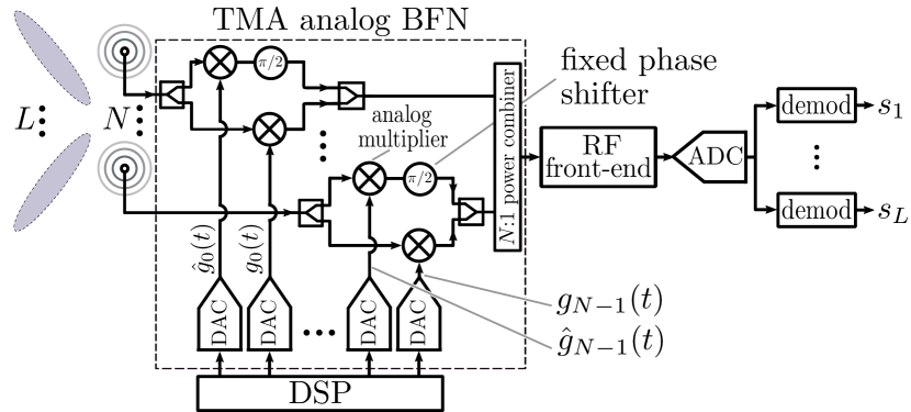
Let us consider a linear array with isotropic elements having unitary static excitations , . As shown in Fig. 1, in the TMA analog BFN, each element excitation is modulated by a pair of periodic pulsed signals: and its Hilbert Transform (HT) , both with fundamental period . We assume that has no direct current (DC) component and, hence, it can be represented by the following trigonometric Fourier series:
| (1) |
where and
| (2) |
are the exponential Fourier series coefficients of , with modulus and phase . Since the are real-valued, such coefficients satisfy the symmetry property . Notice that
| (3) |
because the HT produces a phase shifting to all the Fourier series components in .
The time-varying array factor corresponding to the SSB TM-MBPA with elements treated as shown in Fig. 1 is
| (4) |
where represents the -th array element position on the axis, is the angle with respect to such a main axis, and is the wavenumber. By considering the Fourier Transform (FT) of Eq. 1 and Eq. 3, the frequency domain representation of the SSB TM-MBPA Eq. 4 is
| (5) |
being the unit impulse. Notice that Eq. 5 does not contain negative spectral lines.
Turning back to the time domain, we arrive at the following expression for the SSB TM-MBPA time-varying array factor
| (6) |
where
| (7) |
are the spatial array factors at frequencies , with being the carrier frequency and positive integer numbers. Notice that such array factors depend on the complex-valued coefficients in Eq. 2 and can be used to design an MBPA.
III Control with Periodic Nyquist Pulsed Signals
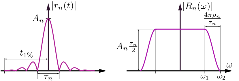
The impact of pulse shaping on the sideband radiation of switched TMAs was studied in [11], whereas the concept of non-switched TMA multiple beamforming was introduced in [12]. In this section, we particularize the control of the previous generic SSB TM-MBPA to periodic Nyquist pulses. The long-established alternative to the non-causal ideal pulse is the well-known Nyquist pulse [10, Chapter 5]
| (8) |
where is the amplitude of the pulse at , is the time separation between zero crossings and is the roll-off factor, which determines the smoothness of the pulse frequency response (see Fig. 2)
|
|
(9) |
being and .
We next proceed to the construction of the periodic pulsed signals following two steps. We start by constructing , the periodic continuation of with fundamental period (see Fig. 3), satisfying the constraint
| (10) |
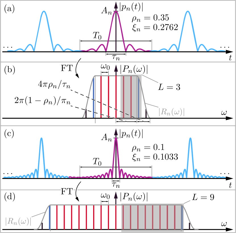
where is the time instant beyond which the asymptotic tail of is entirely below the 1% of its maximum level (see Fig. 2). The restriction in Eq. 10 is set to guarantee a practically negligible time overlapping between consecutive periods (see Figs. 3a and 3c), and hence ensuring that the FT of is a frequency comb at (), with envelope (see Figs. 3b and 3d).
Thus, the Fourier coefficients of satisfy , i.e.,
| (11) |
with , , and . We have particularly selected . Hence, the maximum is and the reason is that time modulation is a bandwidth limited technique which must satisfy [13], being the signal bandwidth.
Notice that is usually a fixed parameter in the TMA technique. Therefore, for a given (see Fig. 3), if decreases, should also decrease to satisfy the constraint in Eq. 10 and, accordingly, increases. Consequently, the lower , the higher the number of selected harmonics, and vice versa. More specifically, given an order of the harmonic beams to be exploited, should be selected to satisfy the following requirements: 1) harmonics are inside the flat zone of the frequency response of (see the red spectral lines in Figs. 3b and 3d) and hence ; 2) harmonics are inside the roll-off zone of , thus the harmonics of order , the exploited harmonics of highest order (see the blue spectral lines in Figs. 3b and 3d), suffer a weak attenuation, whereas the ones at (see the black spectral lines in Figs. 3b and 3d) experience a significant attenuation to keep the TMA efficiency as high as possible. Obviously, the remaining harmonics of higher order are removed. Hence, and .
The second step is to change the phases of the harmonic patterns to endow them with steering capabilities. This can be done by means of the time delays, , introduced through another periodic signal, , also with fundamental period . Indeed, let be
| (12) |
where is the maximum number of harmonics to be exploited (a fixed bound in the design). The exponential Fourier series coefficient of are , with . If we now construct in Eq. 1 as the periodic convolution , the resulting Fourier series coefficients are
| (13) |
Therefore, determines the phase of the excitation of the -th element of the -th order harmonic pattern. We remark that and , operating in accordance with Fig. 1, Eq. 6 and Eq. 7, synthesize an SSB TM-MBPA, hence removing the negative harmonic beams. This is illustrated by the gray-shaded areas in Figs. 3b and 3d with the final useful harmonics appropriately windowed. We also highlight (see Fig. 1) that the core elements of the scheme are wide-band analog multipliers [14, 15, 16, 17]. The periodic pulses are generated in the digital domain and next converted into the analog domain by means of digital-to-analog converters. The DAC sampling frequency, , must be higher than the signal bandwidth [13], hence becoming independent of .
IV Efficiency of the Time Modulation
In this section, we determine the efficiency of the time modulation operation in the proposed SSB TM-MBPA scheme. By virtue of antenna reciprocity, the transmit and receive antenna efficiency is the same. Accordingly, and for the sake of simplicity, we will quantify the efficiency of the time modulation applied to the SSB TM-MBPA in Fig. 1 for the case of transmitting a single carrier with normalized power. Additionally, to simplify the analysis, but without any relevant loss of generality, we will consider a uniform linear array with an inter-element distance of . Such an efficiency, denoted by , can be factorized in two separated efficiencies
| (14) |
whose interpretations are described below.
The efficiency accounts for the competence of the TMA technique to filter out and radiate only the working (or useful) harmonics. It is determined by , where is the total mean radiated power by the SSB TM-MBPA, which is given by the expression [5, (16)] , being the total mean radiated power at the -th harmonic. On the other hand, denotes the useful mean radiated power (since only harmonics are profitably exploited) and obeys to [5, Eq. 16]. It is remarkable that the SSB operation duplicates the value of this efficiency with respect to that of a conventional TMA.
Most of the works in the literature which analyze the TMA efficiency limit themselves to the study of . However, the second component of the efficiency, , accounts for the reduction of the total mean power radiated by a uniform static array caused by the effect of modulating its excitations with periodic pulses. is of critical importance due to its high impact on the antenna gain. This efficiency is evaluated by means of the quotient , where is the total mean power radiated by a uniform static array with elements and is calculated as the total mean transmitted power over the array factor , i.e.,
In order to derive closed-form expressions for both efficiencies, we still have to obtain the expressions of and . In this sense, since is given by [5], bearing in mind Eq. 11 and Eq. 13, and selecting as specified in Section III, we have
Finally, by substituting , and into Eq. 14, we obtain the aforementioned closed-form expressions.
| [dBV] | [dB] | +1 [dB] | [%] | ||||||
|---|---|---|---|---|---|---|---|---|---|
| 3 | 4.52 | 0.35 | 0.28 | 1.27 | 2.35 | 4.89 | -1.44 | -11.28 | 98.86 |
| 5 | 4.99 | 0.21 | 0.18 | 1.18 | 4.42 | 6.78 | -1.32 | -12.20 | 99.52 |
| 9 | 5.49 | 0.10 | 0.10 | 0.97 | 8.73 | 10.67 | -0.42 | -11.49 | 99.76 |
| 15 | 6.22 | 0.05 | 0.06 | 0.79 | 14.92 | 16.49 | -0.06 | -13.25 | 99.92 |
| reference | number | [dBi] | [%] | [%] | [%] |
| of BFNs | |||||
| [4] | 1 | 2.64 | 30.78 | 9.96 | 3.06 |
| [5] | 1 | 4.79 | 54.75 | 23.96 | 13.12 |
| [9] | 3 | 8.22 | 99.79 | 55.55 | 55.44 |
| proposed SSB | 1 | 4.37 | 98.86 | 100 | 98.86 |
| TM-MBPA |
V Numerical Examples
Table I details, for , several configuration examples of an SSB TM-MBPA with =20 elements time-modulated by identical pulses (same and ). The selected values of (leading to the corresponding values of ) allow for exploiting = 3, 5, 9 and 15 harmonics, respectively. According to Section III, such values of locate, in each case, harmonics in the flat zone of the frequency response of the pulses, while the harmonics and are located at the beginning and at the end of the roll-off zone (see , , the attenuation of such harmonics in Table I, and Fig. 3). Notice that the parameter is directly proportional to the roll-off zone width. Hence, Table I shows that when increases, the width of roll-off zone decreases. Consequently, since the separation in frequency between adjacent harmonics is fixed (), when increases, harmonics and are better adjusted to the borders of the roll-off zone, and hence improves. However, if increases, decreases and, if remains fixed, also decreases and consequently also does. Although is independent of for identical pulses, can be improved by means of adjusting , which is not possible in switched TMAs. Table I shows the different values of yielding in each case, and therefore .
For the case =3 (there are no examples in the literature with 3), it is possible to perform a comparison with switched TMAs. Multibeam TMAs with rectangular pulses implemented with single-pole single-throw (SPST) switches are bound to use very close to zero. Additionally, such TMAs have no SSB features (see Table II, [4]), leading to modest values for and and, consequently, low and (mean directivity of the beams). For single-pole dual-throw (SPDT) schemes, the figures of merit are improved but the frequency response of rectangular pulses together with the lack of SSB features still constitute a serious bottleneck (Table II, [5]). One way of improving the performance is to focus on the generation of a single beam by using trapezoidal pulses and endowing the TMA with SSB features [9]. Consequently, it is necessary to consider independent time-modulated BFNs. However, as the pulses remain at zero state for a certain amount of time, cannot achieve the full level of (Table II, [9]). A way of improving is by amplifying the static excitations (amplifiers at ). Consequently, two key benefits of the proposed non-switched TMA scheme are: (1) the safeguard of by amplifying at ; and (2) the use of a single BFN.
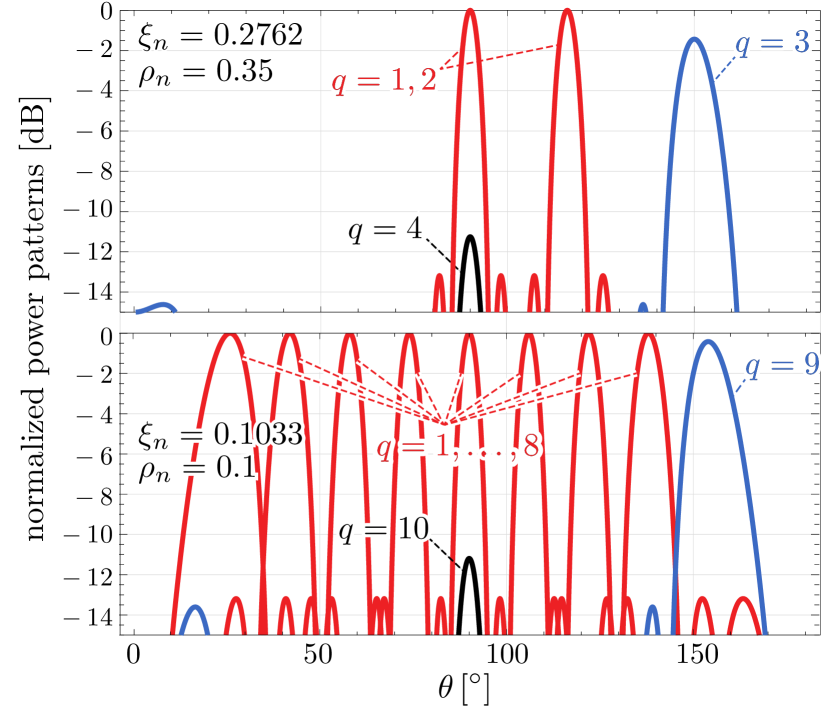
Fig. 4 shows the radiated patterns for the proposed SSB TM-MBPA and the cases =3 (top) and =9 (bottom), respectively. Notice the effect of narrowing the roll-off zone for =9, yielding a better filtering of the exploited higher order harmonics.
VI Conclusions
We have presented a novel MBPA scheme based on time modulation with periodic Nyquist pulsed signals and SSB operation. The proposed SSB TM-MBPA provides excellent levels of power efficiency and reconfigurability. Furthermore, both the performance and the MBPA BFN complexity are invariant to the number of multibeams.
References
- [1] W. Hong, Z. H. Jiang, C. Yu, J. Zhou, P. Chen, Z. Yu, H. Zhang, B. Yang, X. Pang, M. Jiang, Y. Cheng, M. K. T. Al-Nuaimi, Y. Zhang, J. Chen, and S. He, “Multibeam antenna technologies for 5G wireless communications,” IEEE Trans. Antennas Propag., vol. 65, no. 12, pp. 6231–6249, Dec. 2017.
- [2] G. Li, S. Yang, Y. Chen, and Z.-P. Nie, “A novel electronic beam steering technique in time modulated antenna array,” Progress In Electromagnetics Research, vol. 97, pp. 391–405, 2009.
- [3] L. Poli, P. Rocca, G. Oliveri, and A. Massa, “Harmonic beamforming in time-modulated linear arrays,” IEEE Trans. Antennas Propag., vol. 59, no. 7, pp. 2538–2545, Jul. 2011.
- [4] P. Rocca, Q. Zhu, E. Bekele, S. Yang, and A. Massa, “4-D arrays as enabling technology for cognitive radio systems,” IEEE Trans. Antennas Propag., vol. 62, no. 3, pp. 1102–1116, Mar. 2014.
- [5] R. Maneiro Catoira, J. Brégains, J. A. Garcia-Naya, L. Castedo, P. Rocca, and L. Poli, “Performance analysis of time-modulated arrays for the angle diversity reception of digital linear modulated signals,” IEEE J. Sel. Topics Signal Process., vol. 11, no. 2, pp. 247–258, Mar. 2017.
- [6] R. Maneiro-Catoira, J. Brégains, J. A. García-Naya, and L. Castedo, “Time modulated arrays: From their origin to their utilization in wireless communication systems,” Sensors, vol. 17, no. 3, pp. 1–14, Mar. 2017.
- [7] R. Maneiro-Catoira, J. Bregains, J. A. Garcia-Naya, and L. Castedo, “Analog beamforming using time-modulated arrays with digitally preprocessed rectangular sequences,” IEEE Antennas Wireless Propag. Lett., vol. 17, no. 3, pp. 497–500, Mar. 2018.
- [8] R. Maneiro-Catoira, J. Brégains, J. A. García-Naya, and L. Castedo, “Dual-signal transmission using RF precoding and analog beamforming with TMAs,” IEEE Communications Letters, vol. 22, no. 8, pp. 1640–1643, Aug. 2018.
- [9] A. M. Yao, W. Wu, and D. G. Fang, “Single-sideband time-modulated phased array,” IEEE Trans. Antennas Propag., vol. 63, no. 5, pp. 1957–1968, May 2015.
- [10] A. Goldsmith, Wireless Communications. Cambridge University Press, 2005.
- [11] E. T. Bekele, L. Poli, P. Rocca, M. D’Urso, and A. Massa, “Pulse-shaping strategy for time modulated arrays—analysis and design,” IEEE Trans. Antennas Propag., vol. 61, no. 7, pp. 3525–3537, Jul. 2013.
- [12] R. Maneiro Catoira, J. Brégains, J. A. Garcia-Naya, and L. Castedo, “Enhanced time-modulated arrays for harmonic beamforming,” IEEE J. Sel. Topics Signal Process., vol. 11, no. 2, pp. 259–270, Mar. 2017.
- [13] R. Maneiro-Catoira, J. Brégains, J. García-Naya, and L. Castedo, “On the feasibility of time-modulated arrays for digital linear modulations: A theoretical analysis,” IEEE Trans. Antennas Propag., vol. 62, no. 12, pp. 6114–6122, Dec. 2014.
- [14] S. Yuwono, S. Han, and S. Lee, “A 900-mV area-efficient source-degenerated CMOS four-quadrant multiplier with 10.6-GHz bandwidth,” in Proc. of the 5th International Conference on Wireless Communications, Networking and Mobile Computing, Beijing, China, Sep. 2009, pp. 1–4.
- [15] I. Makwana and V. Sheth, “A low power high bandwidth four quadrant analog multiplier in 32 nm CNFET technology,” International Journal of VLSI design & Communication Systems (VLSICS), vol. 3, no. 2, pp. 73–83, Apr. 2012.
- [16] M. Mincica, D. Pepe, and D. Zito, “Cmos uwb multiplier,” IEEE Transactions on Circuits and Systems II: Express Briefs, vol. 58, no. 9, pp. 570–574, Sep. 2011.
- [17] L. Zhou, Y. P. Xu, and F. Lin, “A gigahertz wideband CMOS multiplier for UWB transceiver,” in Proc. of the 2005 IEEE International Symposium on Circuits and Systems, vol. 5, Kobe, Japan, May 2005, pp. 5087–5090.