Resistive Wall Tearing Mode Disruptions
H. R. Strauss 1, B. E. Chapman 2, B. C. Lyons 3
1 HRS Fusion, West Orange, USA
2 Dept. of Physics, University of Wisconsin, Madison WI 53706 USA
2 General Atomics, San Diego, CA 92121 USA
Email: hank@hrsfusion.com
Abstract
This paper deals with resistive wall tearing mode (RWTM) disruptions. RWTMs are closely related to resistive wall modes (RWMs). The nonlinear behavior of these modes is strongly dependent on the resistive wall outside the plasma. A conducting wall is highly mitigating for RWTM disruptions. The consequence for ITER, which has a highly conducting wall, is that the thermal quench (TQ) time could be much longer than previously conjectured. Active feedback stabilization is another possible way to mitigate or prevent RWTM disruptions. Simulations of disruptions are reviewed for DIII-D and MST. MST has a longer resistive wall time than ITER, and disruptions are not observed experimentally when MST is operated as a standard tokamak. Simulations indicate that the RWTM disruption time scale is longer than the experimental shot time. In general, edge cooling by tearing mode island overlap or by impurity radiation causes contraction of the current profile, which destabilizes RWTMs. The equilibria studied here have a rational surface close to the edge of the plasma, and low current density between the surface and the wall. A sequence of low edge current model equilibria has major disruptions only for a resistive, not ideal, wall, and edge This is consistent with typical regimes of tokamak disruption avoidance, suggesting that typical tokamak disruptions could be RWTMs.
1 Introduction
Disruptions are loss of plasma confinement in tokamaks, which could damage large tokamaks like ITER. The thermal flux in an ITER disruption would be intolerable if it occurred on the timescale typical of most present tokamaks. Until recently, the instability which caused locked mode disruptions was not known. Recent work identified the thermal quench in JET locked mode disruptions with a resistive wall tearing mode (RWTM) [1]. The RWTM was also predicted in ITER [2], where it produces a slow self mitigated thermal quench. A similar instability was found in a DIII-D locked mode shot [3, 4]. The MST experiment [5, 6] when operated as a standard tokamak, does not have disruptions. Recent theory and simulations showed this is because the timescale of RWTMs, which could cause a thermal quench, is longer than the experimental pulse time.
The RWTM instability is studied with simulations, theory, and comparison to experimental data. Linear simulations show the mode is stable for an ideal wall, and unstable with a resistive wall. Nonlinear simulations show that the mode grows to large amplitude, causing a thermal quench. The mode onset occurs when the rational surface is sufficiently close to the plasma edge [7], and the edge current density is sufficiently small.
RWTM disruptions can be passively slowed by a highly conducting wall, or actively slowed by feedback. Simulations of feedback stabilization of RWTM disruptions will be presented.
Simulations of a DIII-D disruption show the dependence of the linear growth rate on for large where is the resistive wall penetration time, is the wall minor radius, is the wall thickness, is the wall resistivity, and is the Alfvén time. In the simulations, the RWTMs cause a complete thermal quench, in a time proportional to the linear growth time. There is good agreement between the simulations and experimental data.
Simulations of MST show that RWTMs connect smoothly to RWMs, when the edge , where are poloidal and toroidal mode number. For all , the RWTM growth rate is proportional to and even satisfies the same linear dispersion relation as a RWM. This scaling holds when is sufficiently small, where is the plasma Lundquist number. This might be satisfied in ITER.
The onset condition for RWTMs requires the rational surface to be sufficiently close to the wall. It also requires the current density near the plasma edge to be small. Experimentally, disruptions are often preceded by edge cooling, which causes the current profile to contract. This can happen in locked mode disruptions and density limit disruptions. A sequence of model low edge current equilibria is simulated, showing that major disruptions occur for small enough Only minor disruptions occur if the wall is ideally conducting. Major disruptions only occur when the wall is resistive, indicating that they are RWTMs.
RWTMs can be stabilized passively by a sufficiently conducting wall, which is sufficiently close to the plasma. It appears that active feedback stabilization is also possible. This is illustrated in simulations.
Sec.2 reviews RWTM disruptions, including observed or predicted TQ times for JET, DIII-D, ITER, and MST based on experimental data, theory, and simulations. It suggests a difference in cases with high and low Sec.2.1 summarizes DIII-D locked mode studies. Sec.2.2 reviews MST disruptions, which are not observed due to the short pulse time but are predicted by theory and simulations, and discusses the relation between RWTMs and RWMs. Sec.3 describes current contraction as a precursor to disruptions, with nonlinear studies of contracted equilibria including the effect of a resistive or ideal walls. Sec.4 presents work on feedback stabilization; and Sec.5 gives conclusions.
2 RWTM disruptions
In devices with long resistive wall magnetic perturbation time, the TQ duration produced by RWTMs is long.
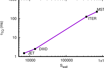
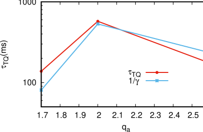
Fig.1 shows the TQ duration as a function of For JET and DIII-D, The TQ duration was obtained from experiment and simulations. In ITER, and in MST For ITER and MST, the TQ value is based on theory and simulations. MST disruptions are not observed experimentally within the the experimental shot time of which sets a lower bound on The simulated There appear to be two regimes of , depending on In MST, the RWTM growth time is proportional to like a RWM. This may also be the case in ITER.
(a)
 (b)
(b)
 (c)
(c)
2.1 DIII-D locked mode disruption
Data from DIII-D locked mode shot 154576 [4] was compared with simulations. During the locked mode, moderate amplitude magnetic perturbations are present. Then an magnetic perturbation grows to large amplitude, and the core temperature is quenched, in time This is followed by a current quench.
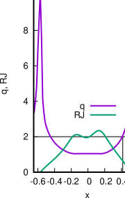
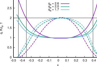
Simulations were carried out using an equilibrium reconstruction before the start of the mode growth. Linear simulations with M3D-C1 [8] found instability with a resistive wall, and stability with an ideally conducting wall, and agreement with linear theory. The RWTM growth rate scales asymptotically as The linear simulations establish that the equilibrium reconstruction is unstable with a resistive wall, and stable with an ideal wall. Initial profiles are shown in Fig.2(a), which indicates that the rational surface is close to the plasma edge, and the toroidal current density is small in the edge. These are typical conditions for RWTM instability. The initial profiles of and toroidal current as a function of where is the plasma major radius. Nonlinear simulations show that the mode grows to large amplitude, sufficient to cause a thermal quench.
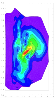
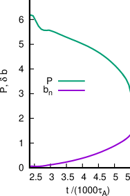
Nonlinear simulations done with M3D [9] show contours of the temperature when the total pressure is of its initial value, in Fig.2 (b). The time history of the total pressure is shown in Fig.2 (c) demonstrating a TQ. The radial magnetic perturbation at the wall is also shown, showing that the growth of the RWTM causes the TQ. Simulations were done with several values of It was found that the TQ time scales as like the linear growth time. For the experimental value the TQ time is in agreement with the data. The simulations also find that the maximum radial magnetic field at the wall agrees with the maximum value in the experiment.
2.2 MST disruptions
Disruptions are not observed in the Madison Symmetric Torus (MST) [5, 6] when the device is operated as a standard tokamak. (At extremely low density, the discharge can contain a large runaway electron component, which will not be considered here.) The predicted growth time of RWTMs is much longer than the experimental shot duration of , which gives a lower limit to the possible TQ time. The predicted linear growth rate is the same as an RWM, even when the surfaces are inside the plasma.
The predicted thermal quench time in MST is much longer than in conventional tokamaks such as JET and DIII-D, and is longer than a prediction for ITER based on RWTMs, as shown in Fig.1. Simulations were done with M3D of equilibrium reconstructions with edge Initial profiles of and are shown in Fig.3(a). They have the typical feature of rational surface near the edge, with low edge current.
In MST, the RWTM growth time scales linearly in the resistive wall penetration time [5]. This is characteristic of large , in which the RWTM asymptotically satisfies the resistive wall mode (RWM) dispersion relation.
The RWTM linear dispersion relation is [5, 11]
| (1) |
where is the plasma Lundquist number, is the poloidal mode number, is the rational surface radius, is the wall radius, Resistive wall tearing modes have ideal - wall tearing parameter and no - wall tearing parameter The RWTM growth rate scalings vary as with In a JET example [1] while in the DIII-D example of Sec.2.1 [3] In MST simulations [5] This is because of the smallness of the left side of (1) Taking edge in JET, with , In DIII-D, with , In MST, with and in ITER, with ITER can be in the linear regime like MST.
Using a model equilibrium [11], the linear growth rate is, neglecting the left side of (1),
| (2) |
This is also the growth rate of a RWM [11]. In this model, is on axis, the normalized toroidal current density is constant within radius , and is zero for larger radius. The crossover from RWTM to RWM occurs smoothly at For the rational surface exits the plasma and the mode becomes a RWM.
(a)
 (b)
(b)
3 Low edge current and RWTM disruptions
A common precursor of disruptions is edge cooling, which causes contraction of the current profile. During locked modes and other disruption precursors in devices like JET and DIII-D, low current and temperature can develop [12] in the plasma edge. This can be caused by tearing mode island overlap, which has been described [4] as a collapse, meaning a minor disruption causing a drop of the temperature at the rational surface. Prior to a major disruption, there can be several minor disruptions. The temperature drop causes the resistivity to increase, and the edge current is suppressed.
Another effect on edge temperature is impurity radiation in the edge or in the core [13]. These effects shape the current profile to be more contracted away from the edge, and to become more flattened in the core. When the edge impurity radiation is large, it may be possible to trigger multifaceted asymmetric radiation from the edge (MARFE) and density limit disruptions [14, 15, 16].
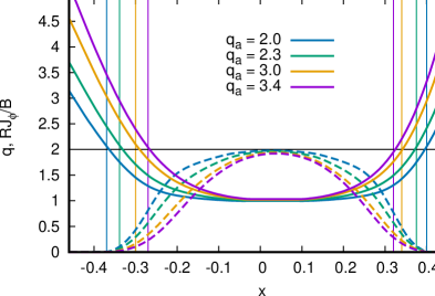
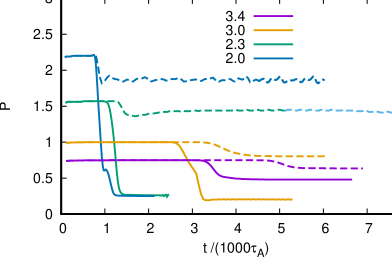
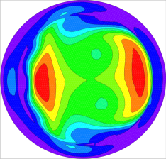
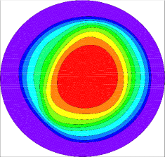
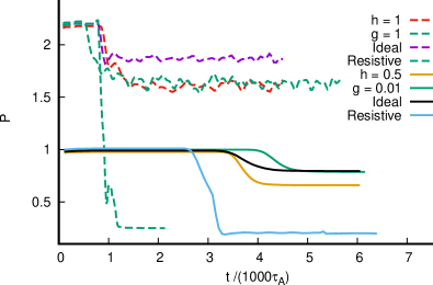
During precursors to a disruption, the plasma edge region cools, causing the current to contract. A model sequence of low edge current equilibria [10] are shown in Fig.4 (a). They were derived from the MST equilibrium with in Fig.3(a) in which the plasma radius was reduced so that as is approximately the case in DIII-D. Linear combinations of the initial current density and the square of the initial current density gave initial states in which on axis and has a range of values Current and profiles as a function of are shown in Fig.4(a). They have the typical feature of near the edge, with small edge current density. There is a striking difference in the results, depending on whether the wall is ideal or resistive. With an ideal wall, the perturbations saturate at moderate amplitude, causing a minor disruption without a thermal quench. Fig.4 shows time histories of total pressure cases with as labeled in the plot. With a resistive wall, indicated with solid curves, there are large perturbations of , which are major disruptions. For there is a minor disruption. With an ideal wall, indicated with dotted curves, there are only small perturbations of , which are minor disruptions.
(a)
 (b)
(b)
(a)
 (b)
(b)
Contours of pressure are shown in Fig.5, comparing two cases with In Fig.5(a), the wall is resistive, which in Fig.5(b), the wall is ideal. The perturbations of are much larger in the resistive wall case. Major disruptions only occur with a resistive wall.
The major disruption onset limit in Fig.4(b) depends on the amount of current contraction. Fig.4(a) shows that the rational surface moves inward as increases. If the rational surface is too far from the wall, RWTMs are stable [10]. In that case, major disruptions do not occur, a result noted in a DIII-D database [3, 7]. The limiting value depends on details of the equilibrium, which will be investigated elsewhere.
These results demonstrate that RWTMs can cause a TQ under typical tokamak conditions for disruptions.
4 Feedback
It was shown in the previous sections than with an ideal wall, only minor disruptions occurred. This suggests that active feedback could make the wall effectively ideal and suppress major disruptions, even for
Feedback experiments on DIII-D [17] and RFX - mod [18] showed stabilization of what was thought to be a RWM. The same approach ought to work for RWTMs.
There have been extensive theoretical studies of feedback stabilization [19, 20, 21, 22]. To model feedback, consider the magnetic diffusion equation at a thin resistive wall [1, 3, 11]
| (3) |
where is the magnetic potential at the wall, is its radial derivative on the plasma side of the wall, are the wall resistivity and thickness, and is the radial derivative of on the vacuum side of the wall. The vacuum field is taken of the form
| (4) |
where is the feedback signal, is the normal gain, is the transverse gain, are screening functions of poloidal and toroidal angle of the wall, modeling the location of the sensors, and is the wall radius. For now, take They could be taken non zero in future numerical studies, might affect detailed predictions of the modeling. To obtain , saddle coils which sense , are required, which is fed back into The measurement can be outside the wall, by continuity of To obtain , probes which sense transverse perturbed magnetic field inside the wall are required, and fed back into Saddle coil sensors were used in RFX - mod [23], filtering the aliasing error. Probes were used in DIII-D [17].
The linear dispersion relation [3] (1) becomes
| (6) |
where When the dispersion relation is that of an ideal wall. The term has to be much larger to have a similar effect.
Nonlinear M3D simulations were carried out using (5) including applied only for toroidal harmonics. The equilibria of Fig.4 were used. Shown in Fig.6 are the total pressure as a function of time for ideal wall, resistive wall, and stabilization for the cases (dashed curves) and (solid curves) of Fig.4. Cases without feedback are reproduced from Fig.4(b) for comparison. For a major disruption is avoided applying feedback, while a similar result is obtained for with Major disruptions are avoided with , The TQ time of major disruptions slows down as in increases. This suggests that feedback is more effective for larger than for It appears more effective using than Using is not as effective as an ideal wall. When feedback experiments [17, 18] were performed, it was not known that RWTMs can cause disruptions. It would be desirable to repeat the experiments at higher to try to prevent disruptions. Further results will be reported elsewhere.
Complex feedback will be studied elsewhere.
5 Conclusion
This article discussed disruptions caused by RWTMs. Linearly, RWTMs have growth times scaling as For moderate such as in JET and DIII-D, For large , as in MST, which could also be the case in ITER. The thermal quench time in disruptions caused by RWTMs is proportional to the linear growth time, which can be orders of magnitude longer for large than for moderate The large growth time has the same scaling as a RWM, and in simulations of MST the RWTM and RWM connect smoothly, as the rational surface moves out of the plasma.
Simulations of a DIII-D disruption [3] were consistent with a RWTM. The mode growth rate, thermal quench time, and model amplitude agreed with experiment. Simulations of MST [5] found a RWM scaling of growth time and the nonlinear thermal quench time.
RWTM unstable equilibria have characteristic and current profiles, in which the rational surface is near the plasma edge, and the edge current density is small. It was noted that common precursors to disruptions can cause low edge temperature, which in turn causes low edge current density. The precursors could be overlapping tearing modes or impurity radiation. The latter could cause density limit disruptions by RWTMs. It was found in simulations of a sequence of low edge current equilibria, that a resistive wall is required for a major disruption, indicating RWTMs. With an ideal wall, there can be minor disruptions. It was found that there is an edge limit for major disruptions, This is typical of empirical tokamak operating limits.
The ideal wall stability suggests that active feedback could prevent major disruptions. Simulations indicate that this is the case. Feedback from probes and saddle coils was modeled, and it appears that probe feedback is more effective. It also was found that it is harder to stabilize than equilibria. This is encouraging for feedback experiments to suppress major disruptions.
The RWTMs and RWMs considered here have low The more well studied high RWMs will be likely to have a high RWTM counterpart, which will be studied in the future.
Acknowledgement This work was supported by U.S. D.O.E. grants DE-SC0020127, DE-SC0020245 and DE-SC0019003.
References
- [1] H. Strauss and JET Contributors, Effect of Resistive Wall on Thermal Quench in JET Disruptions, Phys. Plasmas 28, 032501 (2021)
- [2] H. Strauss, Thermal quench in ITER disruptions, Phys. Plasmas 28 072507 (2021)
- [3] H. Strauss, B. C. Lyons, M. Knolker, Locked mode disruptions in DIII-D and application to ITER, Phys. Plasmas 29 112508 (2022).
- [4] R. Sweeney, W. Choi, M. Austin, et al. , Relationship between locked modes and thermal quenches in DIII-D, Nucl. Fusion 58, 056022 (2018)
- [5] H. R. Strauss, B. E. Chapman, N. C. Hurst, MST Resistive Wall Tearing Mode Simulations, Plasma Phys. Control. Fusion 65 084002 (2023);
- [6] N. C. Hurst, B. E. Chapman, A. F. Almagri, et al. Self-organized magnetic equilibria in tokamak plasmas with very low edge safety factor, Phys. Plasmas 29 080704 2022.
- [7] R. Sweeney, W. Choi, R. J. La Haye, S. Mao, K. E. J. Olofsson, F. A. Volpe, and the DIII-D Team, Statistical analysis of m/n = 2/1 locked and quasi - stationary modes with rotating precursors in DIII-D, Nucl. Fusion 57 0160192 (2017).
- [8] S. C. Jardin, N. Ferraro, J. Breslau, J. and Chen, Comput. Sci. & Disc. 5 014002 (2012)
- [9] W. Park, E. Belova, G. Y. Fu, X. Tang, H. R. Strauss, L. E. Sugiyama, Plasma Simulation Studies using Multilevel Physics Models, Phys. Plasmas 6, 1796 (1999).
- [10] H. R.Strauss, Models of resistive wall tearing mode disruptions, Phys. Plasmas 30, 112507 (2023); doi:10.1063/5.0172375
- [11] J. A. Finn, Resistive wall stabilization of kink and tearing modes Phys. Plasmas 2, 198 (1995)
- [12] F.C. Schuller, Disruptions in tokamaks, Plasma Phys. Controlled Fusion 37, A135 (1995).
- [13] G. Pucella, P. Buratti, E. Giovannozzi, et al. Nucl. Fusion 61 046020 (2021)
- [14] D. R. Ferreira, P. J. Carvalho, C. Sozzi, P. J. Lomas, and JET Contributors, Deep learning for the analysis of disruption precursors based on plasma tomography, Fusion Science and Technology, 76(8), 901-911 (2020).
- [15] B. Lipschultz, B. LaBombard, E. Marmar, M. Pickrell, J. Terry, R. Watterson, and S. Wolfe, Marfe: an edge plasma phenomenon, Nuclear Fusion, 24, 8, 977 (1984).
- [16] M. Giacomin, A. Pau, P. Ricci, O. Sauter, T. Eich, the ASDEX Upgrade team, JET Contributors, and the TCV team, First-Principles Density Limit Scaling in Tokamaks Based on Edge Turbulent Transport and Implications for ITER Phys. Rev. Lett. 128, 185003 (2022)
- [17] J. M. Hanson, J. M. Bialek, M. Baruzzo et al. Phys. Plasmas 21 072107 (2014)
- [18] P. Piovesan, J. M. Hanson, P. Martin et al. Phys. Rev. Lett. 113 045003 (2014)
- [19] C.G. Gimblett, On free boundary instabilities induced by a resistive wall, Nucl. Fusion 26, 617 (1986)
- [20] A. Bondeson and M. Persson, Stabilization by resistive walls and q-limit disruptions in tokamaks, Nucl. Fusion 28, 1887 (1988)
- [21] Y. Q. Liu and A. Bondeson, Active Feedback Stabilization of Toroidal External Modes in Tokamaks, Phys. Rev. Lett., 84 907 (2000).
- [22] D. P. Brennan, J. M. Finn, Control of linear modes in cylindrical resistive magnetohydrodynamics with a resistive wall, plasma rotation, and complex gain, Phys. Plasmas 21, 102507 (2014).
- [23] P. Zanca, L. Marrelli, R. Paccagnella, A. Soppelsa, M. Baruzzo, T. Bolzonella, G. Marchiori, P. Martin and P. Piovesan, Feedback control model of the m = 2, n = 1 resistive wall mode in a circular plasma, Plasma Phys. Control. Fusion 54 094004 (2012).