Self-generated spin-orbit torque driven by anomalous Hall current
Abstract
Spin-orbit torques enable energy-efficient manipulation of magnetization by electric current and hold promise for applications ranging from nonvolatile memory to neuromorphic computing. Here we report the discovery of a giant spin-orbit torque induced by anomalous Hall current in ferromagnetic conductors. This anomalous Hall torque is self-generated as it acts on magnetization of the ferromagnet that engenders the torque. The magnitude of the anomalous Hall torque is sufficiently large to fully negate magnetic damping of the ferromagnet, which allows us to implement a microwave spin torque nano-oscillator driven by this torque. The peculiar angular symmetry of the anomalous Hall torque favors its use over the conventional spin Hall torque in coupled nano-oscillator arrays. The universal character of the anomalous Hall torque makes it an integral part of the description of coupled spin transport and magnetization dynamics in magnetic nanostructures.
Spin-orbit torques (SOTs) are relativistic quantum effects at the heart of spintronic devices such as nonvolatile magnetic memory [1], microwave nano-oscillators [2, 3, 4, 5, 6], ultrafast spectrum analyzers [7] and terahertz emitters [8]. SOTs generated by electric charge currents via spin-orbit coupling (SOC) act on magnetic order parameters of ferromagnets (FM) [9, 10] and antiferromagnets (AFM) [11, 12, 13]. Practical applications of SOTs are based on their ability to efficiently drive nonlinear magnetic dynamics such as switching [14, 15], auto-oscillations [5, 4, 6, 16, 17] and skyrmion transport [18].
SOTs are usually studied in multilayers of FM and non-magnetic materials (NM). The most explored SOTs are spin Hall torque (SHT) originating from SOC in NM layers [9, 1, 5, 19, 20] and Rashba torque (RT) induced by SOC at FMNM interfaces [14]. Recently, several other types of SOTs emerged, including planar Hall torque (PHT) [21], spin-swapping torque [22] and interface-generated torques [23, 24]. Other types of torques such as orbital torque [25] and spin Seebeck torque [26] can be present in FMNM heterostructures as well. The multiplicity of coexistent spin torques of similar magnitude but different origin and symmetry [27, 28, 29] is a challenge for the development of spintronic devices.
SOTs universally present in all magnetic systems are especially important for the formulation of a comprehensive theory of current-driven magneto-dynamics. Here we report the discovery of a universal SOT driven by spin and charge currents of anomalous Hall origin in FM conductors. This anomalous Hall torque (AHT) is self-generated because it acts on magnetization of the FM producing the torque. The magnitude of AHT is sufficiently large to cancel magnetic damping of the FM and thereby drive persistent auto-oscillations of its magnetization. AHT exhibits an unusual angular symmetry that favors its applications in coupled spin torque nano-oscillators (STNOs) for neuromorphic signal processing [30].
Anomalous Hall torque
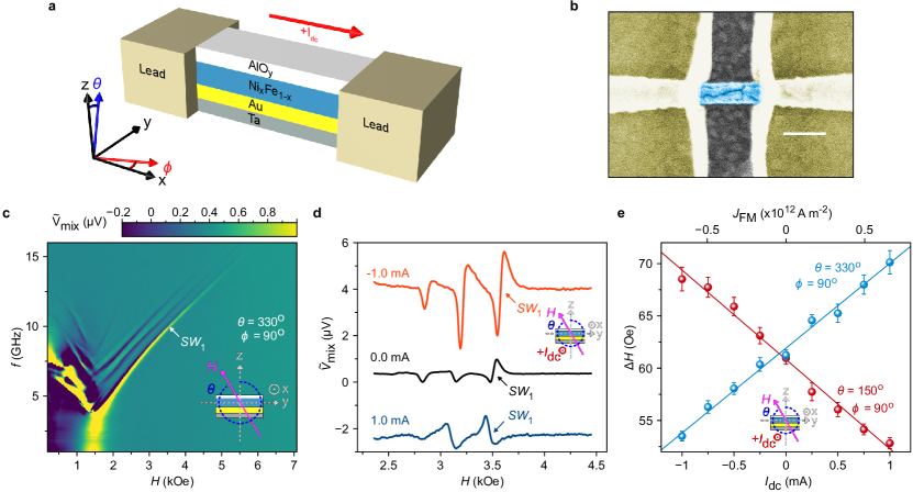
We measure SOTs in substrate nanowire devices (Methods and Supplementary Note 1) schematically shown in Fig. 1(a) along with the coordinate system. Figure 1(b) shows a scanning electron micrograph of such a device. The 171 nm gap between two leads attached to a 56 nm wide, 30 m long nanowire defines the active region where high electric current density is applied. The FM layer allows us to tune the magnitude and sign of the anomalous Hall effect (AHE) via variation of the Ni content . The NM under-layer NM acts as a good sink of spin current generated in the FM and impingent upon the NM1 layer. The NM) capping layer is a poor sink of spin current generated in the FM (Supplementary Note 2). The different spin current absorption properties at the top and bottom surfaces of the FM film are essential for the generation of AHT.
We use spin torque ferromagnetic resonance (ST-FMR) [31] to measure damping-like SOTs acting on magnetization of the FM layer, where is a unit vector and is the FM saturation magnetization (Methods). Room-temperature ST-FMR spectra of the rectified voltage versus external magnetic field and frequency of the applied microwave current reveal multiple spin wave resonances shown in Fig. 1(c) [32]. The discrete spectrum of spin wave eigenmodes arises from geometric confinement to the active region [6]. The data in Fig. 1(c) reveal that is saturated for kOe [33].
A damping-like SOT from the direct current applied to the device tunes the effective magnetic damping of the FM. Since the linewidth of a spin wave resonance is linear in , measurements of probe . Figure 1(d) shows that modifies for applied in the -plane (, ), revealing a damping-like SOT. In these measurements, exceeds the saturation field, which forces to be nearly parallel to the field. Figure 1(e) shows that of the lowest-frequency mode () is linear in , confirming a damping-like SOT in the -plane with efficiency characterized by the slope .
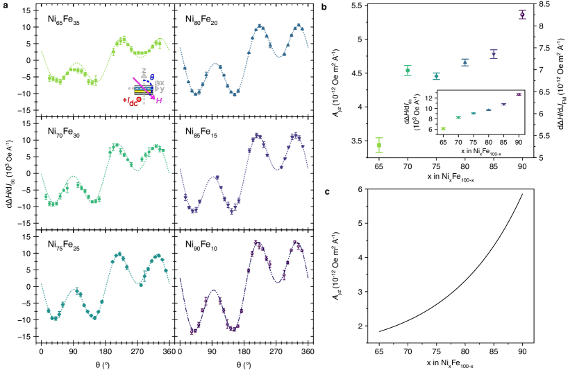
Figure 2(a) shows the dependence of on the direction of in the -plane for six alloy compositions. The expected angular dependence of the SHT- and RT-induced damping in the -plane is while the measured angular dependence is . The lines in Fig. 2(a) are best fits to with fitting parameters and , where is constrained to be identical for all alloy compositions . The fitting gives for all , consistent with small spin Hall angle in Au [32].
The observed angular dependence in Fig. 2(a) coincides with that recently predicted for self-generated AHT [34]. This torque is predicted to arise from -component of anomalous Hall spin and charge currents in a FM conductor, and is applied to magnetization of the same FM conductor. The theory predicts AHT-induced angular-dependent linewidth [34]:
| (1) |
where is the -component of the electric charge current density in the FM, and characterizes the AHT-induced damping efficiency. Equation 1 is not a truncated expansion in odd harmonics because both and terms have identical amplitudes. The unusual angular dependence of Eq. 1 describes our experimental data in Fig. 2(a) well, suggesting that AHT is the dominant SOT in our system.
Using Fig. 2(a), we plot the maximum of (observed at versus in the inset of Fig. 2(b). Measurements of electrical conductivity of the individual FM and NM layers (Supplementary Note 3) allow us to calculate and plot at versus in Fig. 2(b). It is clear from Eq. 1 that is proportional to at : . The data in Fig. 2(b) reveal that increases with increasing concentration of Ni in the alloy. Supplementary Note 4 shows that the measured AHT magnitude is frequency- and field-independent consistent with the AHT theory [34].
Anomalous Hall torque nano-oscillator
The damping-like AHT is sufficiently large to cancel the intrinsic damping of and thereby induce persistent auto-oscillations of [35]. To demonstrate a STNO driven by AHT, we make a 56 nm-wide nanowire device with a 297 nm long active region from a substrate multilayer. Compared to the device in Fig. 1(b), we remove the Au layer in order to (i) increase and thus the magnitude of AHT and (ii) increase anisotropic magnetoresistance (AMR, Supplementary Note 5) and thus the output microwave power. Resistivity measurements of and layers (Supplementary Note 3) show that 87 of flows in the layer.
Spin pumping measurements show that the Ta layer acts as an efficient spin sink in agreement with previous studies (Supplementary Note 2). Therefore, the spin current absorption asymmetry at the top and bottom FM surfaces necessary for the generation of AHT is realized [34]. Figure 3(a) shows ST-FMR spectra for this device measured for applied in the -plane at and . The spectra show multiple spin wave eigenmodes and reveal that is saturated for .
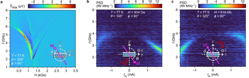
Figure 3(b) shows the spectra of microwave signal spontaneously emitted by the STNO in response to (Methods). To maximize the AHT-induced antidamping, these measurements are made for applied in the -plane at and . The value of below the saturation field creates a small deviation of the equilibrium direction of from the -plane. Such a deviation increases the conversion efficiency of magnetization auto-oscillations into AMR oscillations and boosts the output power [6]. To mitigate detrimental effects of Ohmic heating on the STNO operation at large values of [36], the data in Fig. 3 are collected at 77 K.
Figure 3(b) reveals spontaneous microwave signal generation by the STNO at the lowest-frequency spin wave mode for exceeding the critical value of approximately 0.75 mA. This auto-oscillatory mode shows red frequency shift with increasing primarily due to Ohmic heating that decreases and magnetic shape anisotropy. For , we observe magnoise signal arising from incoherent thermal magnons induced by Ohmic heating [36]. The amplitude of magnoise is significantly lower than that due to the coherent auto-oscillations at . Figure 3(c) shows that reversal of leads to auto-oscillatory dynamics for negative , as expected from Eq. 1.
Our observation of large AHT in the devices with different NM1 layers and is consistent with the mechanism of AHT, which only requires asymmetry of spin current absorption at the top and bottom surfaces of the FM film [34] as discussed in the next section.
Discussion
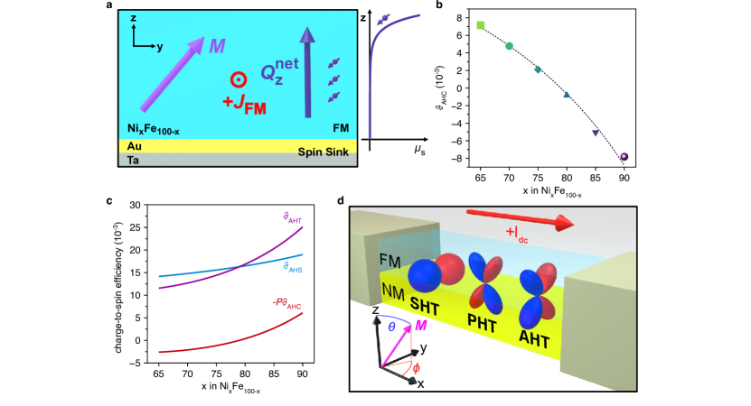
The origin of the self-generated AHT [34] is schematically illustrated in Fig. 4(a). A charge current density in the FM generates a transverse anomalous Hall spin current density flowing along the -axis [37]. The origin of is SOC in the FM, its magnitude depends on the FM electronic band structure and its direction is collinear with the spin angular momentum it carries. The vector generally has components parallel and perpendicular to [37]. Since only the component parallel to contributes to the damping-like AHT [34], we neglect the perpendicular component and assume .
The magnitude of depends on the direction of [37]: where is reduced Planck constant, is electron charge and is a material-specific dimensionless parameter describing the conversion efficiency of into . Here is a spin-sector analog of the anomalous Hall angle in the charge sector, where quantifies the conversion of into transverse anomalous Hall charge current density . In the literature [37], is usually split onto two terms: spin Hall angle and spin anomalous Hall angle . For the physics of AHT, only the algebraic sum is relevant [37, 34].
While characterizes the anomalous Hall spin current in an infinite FM, another contribution to the transverse spin current is present in a FM film [38, 34] due to generating charge accumulation at the top and bottom surfaces of the FM film (Supplementary Note 6). This charge accumulation drives a counter-flow charge current density along the -axis. The counter-flow charge current is spin-polarized along , which gives rise to a counter-flow spin current density [37], where is intrinsic spin polarization of charge current in the FM.
The magnitude of the net transverse spin current density in the FM film is the sum of and :
| (2) |
Asymmetric spin current sinks at the top and bottom surfaces of the FM film give rise to an asymmetric spatial profile of spin accumulation driven by , as illustrated in Fig. 4(a). A significant spin accumulation is created at the FM interface with a poor spin sink NM2, and at the interface with a good spin sink NM1. This creates a net current-driven spin accumulation within the FM film .
For the direction of shown in Fig. 4(a), the magnetic moment of is opposite to . Such spin accumulation can give rise to antidamping spin torque applied to . The mechanism of such torque can be either magnonic or induced by a symmetry-breaking SOC at the FMNM2 interface [34]. In the magnonic mechanism, relaxes via generation of an non-equilibrium magnon cloud, which in turn interacts with the quasi-uniform dynamic mode of and thereby decreases the mode’s effective damping [34, 26]. The conversion efficiency of into the damping-like AHT depends on the direction of and the symmetry of the magnetic system [34]. For a thin-film FM with rotation symmetry around -axis, the conversion efficiency of into current-induced damping is proportional to [34]. Assuming maximum efficiency of spin angular momentum transfer from to the quasi-uniform mode of allowed by symmetry (Supplementary Note 7):
| (3) |
where is the FM layer thickness and is the dimensionless AHT coefficient:
| (4) |
The derivation of Eq. 3 neglects the effect of magnetic anisotropy on the linewidth . This is a reasonable approximation because used in the measurements of significantly exceeds the saturation field.
The angular dependence of the current-induced damping given by Eq. 3 is in full agreement with our experimental data in Fig. 2(a) described by Eq. 1. Equation 2 clearly shows that the observed damping-like torque is driven by a combination of the anomalous Hall spin and charge currents in the FM film, which justifies naming this torque the self-generated AHT.
Comparison of Eq. 1 and Eq. 3 gives the AHT-induced damping efficiency (Supplementary Note 7):
| (5) |
The current-induced damping described by Eq. 3 corresponds to the AHT vector applied to [34]:
| (6) |
where is the absolute value of the electron gyromagnetic ratio. This vector form of AHT can be directly used in micromagnetic simulations in the presence of AHT (Supplementary Note 8).
The dependence of on the FM alloy composition can be calculated from Eq. 4 and Eq. 5, provided the dependence of , , , and on is known. We measure for our samples as shown in Fig. 4(b) (Supplementary Note 5). The function and the values of and for Fe and Ni are known [37], which allows us to approximate and shown in Fig. 4(c) along with their sum, , by interpolating functions (Supplementary Note 7). This figure reveals that for is predominantly determined by the anomalous Hall spin current . The counter-flow current contribution is smaller but non-negligible, and does not change sign as a function of in agreement with the data in Fig. 2(b).
Figure 2(c) shows calculated from Eq. 5. The agreement between the measured in Fig. 2(b) and the predicted in Fig. 2(c) is very good given that no fitting parameters are used in the calculation. The theory accurately captures the sign of , is overall magnitude and its monotonic increase with . Since the theory of Eq. 3 through Eq. 5 captures the angular dependence, the magnitude, the sign and the alloy composition dependence of the measured damping-like SOT, we conclude that this SOT is indeed the self-generated AHT [34]. The residual differences between the measured and predicted are likely a result of the approximations used in the calculation of : (i) the use of interpolating functions for and , (ii) neglecting magnetic anisotropy contributions to in Eq. 3 and (iii) approximating the top and bottom FMNM interfaces by perfectly good and poor spin sinks, respectively. The critical current of the AHT-based STNO predicted by the theory (Supplementary Note 9) is similar to its measured value in Fig. 3(b) as well.
Figure 4(c) demonstrates that and can add constructively to enhance . This holds promise for engineering of magnetic materials with giant AHT, because materials with [39] and [40] far exceeding those of have recently been found. A systematic search aiming to maximize is likely to yield materials with giant AHT, which is very promising because the magnitude of AHT in is already similar to that of the giant SHT in Pt [9].
The mechanism of AHT is analogous to the mechanism of the self-generated PHT in FM conductors [21, 34]. In the case of PHT, a transverse spin current in a FM along -axis is generated by the SOC that gives rise to AMR and planar Hall effect (PHE). The dependence of this transverse planar Hall spin current on is different from that of the anomalous Hall spin current given by Eq. 2, resulting in the angular dependence of PHT-induced damping different from that of Eq. 3 [21, 34].
Figure 4(d) illustrates the dependence of current-induced damping on the direction of due to SHT, PHT [21] and AHT (Eq. 3) in a FMNM bilayer. While the effect of SHT on damping is maximized for along the -axis, both AHT and PHT do not modify the damping for in the -plane and along the -axis. AHT is active in the -plane while PHT is active in the -plane. Given that AMR and AHE are generally non-zero in a FM conductor, we expect AHT and PHT to be universally present in FM systems with spin sink asymmetry. Therefore, AHT and PHT should be a part of the general description of SOTs in systems with FM conductors. Furthermore, AFM conductors have been shown to exhibit AMR and AHE [41]; therefore, we expect PHT and AHT to be relevant for AFM spintronics.
The peculiar angular dependence of AHT and PHT makes these torques ideal candidates for STNO arrays coupled via spin waves [42]. Indeed, STNO coupling via spin waves demands a large out-of-plane component of [35, 42]. However, Fig. 4(d) shows that SHT efficiency decreases when rotates out of the sample plane, leading to large currents and reduced energy efficiency in SHT-based coupled STNO arrays. In contrast, STNOs based on AHT or PHT are expected to show maximum efficiency for having a large out-of-plane component. Coupled STNOs hold promise for neuromorphic signal processing [43, 3].
The self-generated AHT described here is fundamentally different from previously studied torques induced by anomalous Hall currents. Anomalous Hall spin currents can be used to transfer angular momentum from one FM conductor to another via a NM spacer in a FMNMFM2 multilayer, which gives rise to spin transfer torque induced by anomalous Hall currents [38, 44, 45, 46]. Anomalous Hall current in a single FM conductor also gives rise to anomalous spin-orbit torque (ASOT) [47]. ASOT is equal in magnitude but opposite in direction at the top and bottom surfaces of the FM film, leading to fanning of across the FM film thickness rather than to modification of the FM damping.
Self-generated SOTs of origins different from AHT have been observed in several systems [48, 32, 47, 49, 50, 51, 39] (Supplementary Note 8). A combination of Dresselhaus and Rashba SOC terms gives rise to self-generated SOTs in a (Ga,Mn)As FM semiconductor with broken bulk crystal inversion symmetry [48]. Field-free switching due to a self-generated SOT has been demonstrated in FM layers where a chemical composition gradient along the film thickness leads to bulk inversion symmetry breaking [50, 51]. These torques have angular symmetry different from AHT and, in contrast to AHT, modify the FM damping for in the -plane [39].
Conclusions
The universal AHT reported here opens new venues of research in spintronics and magnonics. The peculiar angular symmetry of AHT can drive unusual dynamics of magnetic textures such as skyrmions, vortices, and domain walls. Magnetization reversal process in non-volatile SOT memories is generally affected by AHT, and development of energy-efficient switching strategies that take advantage of AHT is needed. The symmetry of AHT is ideal for energy-efficient coupling of STNOs, and arrays of AHT-based STNOs can be explored for neuromorphic computing applications. A systematic search of materials supporting giant anomalous Hall spin and charge currents is likely to yield systems with very large AHT.
AHT, along with SHT and PHT, forms a triad of universal Hall-type SOTs active in FMNM systems. Therefore, AHT is an integral part of the general description of coupled spin transport and magnetization dynamics in magnetic heterostructures.
Methods
Sample description. The multilayer films were deposited by dc magnetron sputtering on Al2O3(0001) substrates in 2 mTorr of Ar process gas. Highly resistive, amorphous Ta seed layer was used to reduce the multilayer roughness while the highly conductive Au spacer in the multilayer was employed for enhancement of the microwave drive field applied to the magnetization in ST-FMR measurements. The Au spacer was removed in the multilayer used for fabrication of the AHT STNO. Naturally oxidized AlOy layer was used as a cap to prevent oxidation of . The multilayers were patterned into 56 nm wide, 30 m long nanowires by means of electron-beam lithography using DisChem H-SiQ negative resist and Ar ion mill etching. The electric leads to the nanowire were patterned via electron-beam lithography using a methyl methacrylatepoly(methyl methacrylate) positive resist bilayer followed by deposition of and liftoff. The spacing between the leads defined an active region nm long in the series of nanowire samples. The active region of the STNO nanowire device was was nm long.
Spin torque ferromagnetic resonance. We employ field-modulated spin torque ferromagnetic resonance (ST-FMR) to measure the linewidths of spin wave modes as a function of in the nanowire devices [31]. All ST-FMR measurements reported in this article are made in the linear regime of magnetization dynamics. Application of a microwave current to the sample excites forced magnetization oscillations at the drive frequency by a combination of SOT and Oersted field from the microwave current in NM layers adjacent to the FM. Owing to AMR, the magnetization oscillations produce resistance oscillations at the frequency of the drive, which mix with the applied microwave current and generate the rectified voltage Vmix. Resonances in Vmix are observed at the microwave drive frequency and applied magnetic field values corresponding to spin wave eigenmodes. To enhance ST-FMR signal-to-noise ratio, we employ phase-sensitive detection. Here, the applied magnetic field is modulated and the ac voltage is measured using a lock-in amplifier [31]. The measured signal is proportional to magnetic field derivative of the rectified voltage . The linewidth of the spin wave eigenmodes is extracted via fitting the resonances in to a sum of magnetic field derivatives of the symmetric and anti-symmetric Lorentzian functions [31]. Here the linewidth is defined as half-width-at-half-maximum of the Lorentzian function.
Microwave emission. Microwave power spectral density generated by the AHT STNO is measured using a standard circuit based on a microwave spectrum analyser and a low-noise direct current source. A direct current is applied to the device through the low-frequency port of a bias tee. The microwave signal generated by the nanowire is taken from the high-frequency port of the bias tee, amplified by a low-noise 33 dB microwave amplifier, and recorded by the microwave spectrum analyzer. These measurements are made with the sample submerged in a liquid nitrogen bath . The values of the power spectral density reported here are those delivered to a 50 load with the frequency-dependent circuit amplification calibrated out.
Data availability
All data generated or analysed during this study are included in this published article and are available from the corresponding author on reasonable request.
References
- Liu et al. [2012a] L. Liu, C.-F. Pai, Y. Li, H. W. Tseng, D. C. Ralph, and R. A. Buhrman, Science 336, 555 (2012a).
- Haidar et al. [2019] M. Haidar, A. A. Awad, M. Dvornik, R. Khymyn, A. Houshang, and J. Åkerman, Nature Communications 10, 2362 (2019).
- Zahedinejad et al. [2022] M. Zahedinejad, H. Fulara, R. Khymyn, A. Houshang, M. Dvornik, S. Fukami, S. Kanai, H. Ohno, and J. Åkerman, Nature Materials 21, 81 (2022).
- Demidov et al. [2012] V. E. Demidov, S. Urazhdin, H. Ulrichs, V. Tiberkevich, A. Slavin, D. Baither, G. Schmitz, and S. O. Demokritov, Nature Materials 11, 1028 (2012).
- Liu et al. [2012b] L. Liu, C.-F. Pai, D. C. Ralph, and R. A. Buhrman, Physical Review Letters 109, 186602 (2012b).
- Duan et al. [2014a] Z. Duan, A. Smith, L. Yang, B. Youngblood, J. Lindner, V. E. Demidov, S. O. Demokritov, and I. N. Krivorotov, Nature Communications 5, 5616 (2014a).
- Litvinenko et al. [2022] A. Litvinenko, A. Sidi El Valli, V. Iurchuk, S. Louis, V. Tyberkevych, B. Dieny, A. N. Slavin, and U. Ebels, Nano Letters 22, 1874 (2022).
- Seifert et al. [2016] T. Seifert, S. Jaiswal, U. Martens, J. Hannegan, L. Braun, P. Maldonado, F. Freimuth, A. Kronenberg, J. Henrizi, I. Radu, E. Beaurepaire, Y. Mokrousov, P. M. Oppeneer, M. Jourdan, G. Jakob, D. Turchinovich, L. M. Hayden, M. Wolf, M. Münzenberg, M. Kläui, and T. Kampfrath, Nature Photonics 10, 483 (2016).
- Ando et al. [2008] K. Ando, S. Takahashi, K. Harii, K. Sasage, J. Ieda, S. Maekawa, and E. Saitoh, Physical Review Letters 101, 036601 (2008).
- Huang et al. [2021] X. Huang, S. Sayed, J. Mittelstaedt, S. Susarla, S. Karimeddiny, L. Caretta, H. Zhang, V. A. Stoica, T. Gosavi, F. Mahfouzi, Q. Sun, P. Ercius, N. Kioussis, S. Salahuddin, D. C. Ralph, and R. Ramesh, Advanced Materials 33, 2008269 (2021).
- Wadley et al. [2016] P. Wadley, B. Howells, J. Železný, C. Andrews, V. Hills, R. P. Campion, V. Novák, K. Olejník, F. Maccherozzi, S. S. Dhesi, S. Y. Martin, T. Wagner, J. Wunderlich, F. Freimuth, Y. Mokrousov, J. Kuneš, J. S. Chauhan, M. J. Grzybowski, A. W. Rushforth, K. W. Edmonds, B. L. Gallagher, and T. Jungwirth, Science 351, 587 (2016).
- Yan et al. [2022] G. Q. Yan, S. Li, H. Lu, M. Huang, Y. Xiao, L. Wernert, J. A. Brock, E. E. Fullerton, H. Chen, H. Wang, and C. R. Du, Advanced Materials 34, 2200327 (2022).
- Higo et al. [2022] T. Higo, K. Kondou, T. Nomoto, M. Shiga, S. Sakamoto, X. Chen, D. Nishio-Hamane, R. Arita, Y. Otani, S. Miwa, and S. Nakatsuji, Nature 607, 474 (2022).
- Miron et al. [2011] I. M. Miron, K. Garello, G. Gaudin, P.-J. Zermatten, M. V. Costache, S. Auffret, S. Bandiera, B. Rodmacq, A. Schuhl, and P. Gambardella, Nature 476, 189 (2011).
- Petrović et al. [2021] M. D. Petrović, P. Mondal, A. E. Feiguin, P. Plecháč, and B. K. Nikolić, Physical Review X 11, 021062 (2021).
- Hache et al. [2020] T. Hache, Y. Li, T. Weinhold, B. Scheumann, F. J. T. Gonçalves, O. Hellwig, J. Fassbender, and H. Schultheiss, Applied Physics Letters 116, 192405 (2020).
- Hamadeh et al. [2023] A. A. Hamadeh, D. Slobodianiuk, R. Moukhader, G. Melkov, V. Borynskyi, M. Mohseni, G. Finocchio, V. Lomakin, R. Verba, G. de Loubens, P. Pirro, and O. Klein, Science Advances 9, eadk1430 (2023).
- Woo et al. [2016] S. Woo, K. Litzius, B. Krüger, M.-Y. Im, L. Caretta, K. Richter, M. Mann, A. Krone, R. M. Reeve, M. Weigand, P. Agrawal, I. Lemesh, M.-A. Mawass, P. Fischer, M. Kläui, and G. S. D. Beach, Nature Materials 15, 501 (2016).
- Li et al. [2021] P. Li, L. J. Riddiford, C. Bi, J. J. Wisser, X.-Q. Sun, A. Vailionis, M. J. Veit, A. Altman, X. Li, M. DC, S. X. Wang, Y. Suzuki, and S. Emori, Physical Review Materials 5, 064404 (2021).
- Ikebuchi et al. [2022] T. Ikebuchi, Y. Shiota, T. Ono, K. Nakamura, and T. Moriyama, Applied Physics Letters 120, 072406 (2022).
- Safranski et al. [2020] C. Safranski, J. Z. Sun, J.-W. Xu, and A. D. Kent, Physical Review Letters 124, 197204 (2020).
- Pauyac et al. [2018] C. O. Pauyac, M. Chshiev, A. Manchon, and S. A. Nikolaev, Physical Review Letters 120, 176802 (2018).
- Belashchenko et al. [2020] K. D. Belashchenko, A. A. Kovalev, and M. van Schilfgaarde, Physical Review B 101, 020407 (2020).
- Hibino et al. [2021] Y. Hibino, T. Taniguchi, K. Yakushiji, A. Fukushima, H. Kubota, and S. Yuasa, Nature Communications 12, 6254 (2021).
- Lee et al. [2021] D. Lee, D. Go, H.-J. Park, W. Jeong, H.-W. Ko, D. Yun, D. Jo, S. Lee, G. Go, J. H. Oh, K.-J. Kim, B.-G. Park, B.-C. Min, H. C. Koo, H.-W. Lee, O. Lee, and K.-J. Lee, Nature Communications 12, 6710 (2021).
- Safranski et al. [2017] C. Safranski, I. Barsukov, H. K. Lee, T. Schneider, A. A. Jara, A. Smith, H. Chang, K. Lenz, J. Lindner, Y. Tserkovnyak, M. Wu, and I. N. Krivorotov, Nature Communications 8, 117 (2017).
- Garello et al. [2013] K. Garello, I. M. Miron, C. O. Avci, F. Freimuth, Y. Mokrousov, S. Blügel, S. Auffret, O. Boulle, G. Gaudin, and P. Gambardella, Nature Nanotechnology 8, 587 (2013).
- Dc et al. [2023] M. Dc, D.-F. Shao, V. D.-H. Hou, A. Vailionis, P. Quarterman, A. Habiboglu, M. B. Venuti, F. Xue, Y.-L. Huang, C.-M. Lee, M. Miura, B. Kirby, C. Bi, X. Li, Y. Deng, S.-J. Lin, W. Tsai, S. Eley, W.-G. Wang, J. A. Borchers, E. Y. Tsymbal, and S. X. Wang, Nature Materials 22, 591 (2023).
- Gibbons et al. [2022] J. Gibbons, T. Dohi, V. P. Amin, F. Xue, H. Ren, J.-W. Xu, H. Arava, S. Shim, H. Saglam, Y. Liu, J. E. Pearson, N. Mason, A. K. Petford-Long, P. M. Haney, M. D. Stiles, E. E. Fullerton, A. D. Kent, S. Fukami, and A. Hoffmann, Physical Review Applied 18, 024075 (2022).
- Romera et al. [2022] M. Romera, P. Talatchian, S. Tsunegi, K. Yakushiji, A. Fukushima, H. Kubota, S. Yuasa, V. Cros, P. Bortolotti, M. Ernoult, D. Querlioz, and J. Grollier, Nature Communications 13, 883 (2022).
- Gonçalves et al. [2013] A. M. Gonçalves, I. Barsukov, Y.-J. Chen, L. Yang, J. A. Katine, and I. N. Krivorotov, Applied Physics Letters 103, 172406 (2013).
- Safranski et al. [2019] C. Safranski, E. A. Montoya, and I. N. Krivorotov, Nature Nanotechnology 14, 27 (2019).
- Duan et al. [2014b] Z. Duan, C. T. Boone, X. Cheng, I. N. Krivorotov, N. Reckers, S. Stienen, M. Farle, and J. Lindner, Phys. Rev. B 90, 024427 (2014b).
- Ochoa et al. [2021] H. Ochoa, R. Zarzuela, and Y. Tserkovnyak, Journal of Magnetism and Magnetic Materials 538, 168262 (2021).
- Slavin and Tiberkevich [2009] A. Slavin and V. Tiberkevich, IEEE Transactions on Magnetics 45, 1875 (2009).
- Demidov et al. [2011] V. E. Demidov, S. Urazhdin, E. R. J. Edwards, M. D. Stiles, R. D. McMichael, and S. O. Demokritov, Physical Review Letters 107, 107204 (2011).
- Amin et al. [2019] V. P. Amin, J. Li, M. D. Stiles, and P. M. Haney, Physical Review B 99, 220405 (2019).
- Taniguchi et al. [2015] T. Taniguchi, J. Grollier, and M. D. Stiles, Physical Review Applied 3, 044001 (2015).
- Céspedes-Berrocal et al. [2021] D. Céspedes-Berrocal, H. Damas, S. Petit-Watelot, D. Maccariello, P. Tang, A. Arriola-Córdova, P. Vallobra, Y. Xu, J.-L. Bello, E. Martin, S. Migot, J. Ghanbaja, S. Zhang, M. Hehn, S. Mangin, C. Panagopoulos, V. Cros, A. Fert, and J.-C. Rojas-Sánchez, Advanced Materials 33, 2007047 (2021).
- Liu et al. [2018] E. Liu, Y. Sun, N. Kumar, L. Muechler, A. Sun, L. Jiao, S.-Y. Yang, D. Liu, A. Liang, Q. Xu, J. Kroder, V. Süß, H. Borrmann, C. Shekhar, Z. Wang, C. Xi, W. Wang, W. Schnelle, S. Wirth, Y. Chen, S. T. B. Goennenwein, and C. Felser, Nature Physics 14, 1125 (2018).
- Nakatsuji et al. [2015] S. Nakatsuji, N. Kiyohara, and T. Higo, Nature 527, 212 (2015).
- Awad et al. [2017] A. A. Awad, P. Dürrenfeld, A. Houshang, M. Dvornik, E. Iacocca, R. K. Dumas, and J. Åkerman, Nature Physics 13, 292 (2017).
- Hassan et al. [2019] O. Hassan, R. Faria, K. Y. Camsari, J. Z. Sun, and S. Datta, IEEE Magnetics Letters 10, 1 (2019).
- Gibbons et al. [2018] J. D. Gibbons, D. MacNeill, R. A. Buhrman, and D. C. Ralph, Physical Review Applied 9, 064033 (2018).
- Bose et al. [2018] A. Bose, D. Lam, S. Bhuktare, S. Dutta, H. Singh, Y. Jibiki, M. Goto, S. Miwa, and A. Tulapurkar, Physical Review Applied 9, 064026 (2018).
- Sun et al. [2019] C. Sun, J. Deng, S. M. Rafi-Ul-Islam, G. Liang, H. Yang, and M. B. A. Jalil, Physical Review Applied 12, 034022 (2019).
- Wang et al. [2019] W. Wang, T. Wang, V. P. Amin, Y. Wang, A. Radhakrishnan, A. Davidson, S. R. Allen, T. J. Silva, H. Ohldag, D. Balzar, B. L. Zink, P. M. Haney, J. Q. Xiao, D. G. Cahill, V. O. Lorenz, and X. Fan, Nature Nanotechnology 14, 819 (2019).
- Kurebayashi et al. [2014] H. Kurebayashi, J. Sinova, D. Fang, A. C. Irvine, T. D. Skinner, J. Wunderlich, V. Novák, R. P. Campion, B. L. Gallagher, E. K. Vehstedt, L. P. Zârbo, K. Výborný, A. J. Ferguson, and T. Jungwirth, Nature Nanotechnology 9, 211 (2014).
- Zhu et al. [2020] L. Zhu, X. S. Zhang, D. A. Muller, D. C. Ralph, and R. A. Buhrman, Advanced Functional Materials 30, 2005201 (2020).
- Liu et al. [2020] L. Liu, J. Yu, R. González-Hernández, C. Li, J. Deng, W. Lin, C. Zhou, T. Zhou, J. Zhou, H. Wang, R. Guo, H. Y. Yoong, G. M. Chow, X. Han, B. Dupé, J. Železný, J. Sinova, and J. Chen, Physical Review B 101, 220402 (2020).
- Zheng et al. [2021] Z. Zheng, Y. Zhang, V. Lopez-Dominguez, L. Sánchez-Tejerina, J. Shi, X. Feng, L. Chen, Z. Wang, Z. Zhang, K. Zhang, B. Hong, Y. Xu, Y. Zhang, M. Carpentieri, A. Fert, G. Finocchio, W. Zhao, and P. Khalili Amiri, Nature Communications 12, 4555 (2021).
Acknowledgements
This work was supported by the National Science Foundation (ECCS-2213690). Materials development for this project was supported by the National Science Foundation (DMREF-2324203). Device development and nanofabrication for this project was supported by the National Science Foundation Materials Research Science and Engineering Center program through the UC Irvine Center for Complex and Active Materials (DMR-2011967). The authors acknowledge the use of facilities and instrumentation at the UC Irvine Materials Research Institute (IMRI), which is supported in part by the National Science Foundation through the UC Irvine Materials Research Science and Engineering Center (DMR-2011967). The use of facilities and instrumentation at the Integrated Nanosystems Research Facility (INRF) in the Samueli School of Engineering at the University of California Irvine is also acknowledged.
Author contributions
E.A.M. and I.N.K. designed the study. E.A.M. formulated the experimental approach. X.P. and E.A.M. deposited the multilayer samples, performed device and film level experiments, developed the nanofabrication process, and made the nano-devices. All authors wrote the manuscript and discussed the results.
Competing interests
The authors declare no competing interests.