Universal control of four singlet-triplet qubits
Abstract
The coherent control of interacting spins in semiconductor quantum dots is of strong interest for quantum information processing as well as for studying quantum magnetism from the bottom up. On paper, individual spin-spin couplings can be independently controlled through gate voltages, but nonlinearities and crosstalk introduce significant complexity that has slowed down progress in past years. Here, we present a germanium quantum dot array with full and controllable interactions between nearest-neighbor spins. As a demonstration of the level of control, we define four singlet-triplet qubits in this system and show two-axis single-qubit control of all qubits and SWAP-style two-qubit gates between all neighbouring qubit pairs. Combining these operations, we experimentally implement a circuit designed to generate and distribute entanglement across the array. These results highlight the potential of singlet-triplet qubits as a competing platform for quantum computing and indicate that scaling up the control of quantum dot spins in extended bilinear arrays can be feasible.
The coherent control of a large-scale array of spins in the solid state represents a major challenge in the field of quantum-coherent nanoscience [1, 2, 3, 4]. As a quintessential platform for quantum spin control, the lithographically-defined semiconductor quantum dot has shown great promise both for fault-tolerant digital quantum computationo [5, 6, 7, 8, 9, 10, 11, 12, 13, 14, 15] and for analog quantum simulation of emergent quantum phenomena [16, 17, 18, 19]. Nevertheless, the inherent nanoscale dimensions of the devices, the geometrical constraints in integrating all the required components, and the necessity of employing high-frequency electromagnetic fields in cryogenic environments present important challenges for the integration and control a large number of spins.
Already, significant efforts have been undertaken to tackle these challenges. For single-spin qubits, the number of coherently controlled spins has been scaled up to six in a one-dimensional array [11] and four in a two-dimensional array [10]. A six-dot linear array was also used to achieve universal control of two qubits that are each encoded in a subspace of three electron spins distributed over three dots [15]. For singlet-triplet qubits defined in a subspace of two spins across two dots, recent progress includes the individual control of three to four uncoupled qubits [20, 21] and the operation of a single qubit in a quantum dot array [22].
Similar to exchange-only qubits, singlet-triplet qubits [6, 23, 24, 25, 13, 26, 14, 27, 28, 29, 30, 21] allow fully electrical qubit control using baseband voltage pulses. The use of baseband-only control signals can avoid commonly encountered problems of single-spin qubits such as microwave heating effects [31, 11, 32] and may furthermore alleviate crosstalk effects [33]. Singlet-triplet qubits also map naturally to the spin-readout basis in Pauli spin blockade (PSB), which is a common method for spin-to-charge conversion in quantum dots [34, 24]. By using pulse optimization, single-qubit control fidelities of single-triplet qubits have exceeded [28], whereas two-qubit gate fidelities relying on the relatively weak capacitive (Coulomb) interaction reached 72-90% [13, 14]. In theory, the two-qubit gate fidelity can be further improved by replacing the capacitive coupling with the stronger exchange coupling [29], although it has been little investigated in experiments [35]. Despite this progress, universal control of more than two interacting singlet-triplet qubits remains yet to be achieved. Recently, a controlled number of charge carriers were loaded in arrays, a array and a array [36, 37, 38, 39, 40]. These advances set the stage for exploring the operation of three or more interacting singlet-triplet qubits experimentally.
Here we demonstrate coherent control of four interacting singlet-triplet qubits in a 2x4 germanium quantum dot array, which forms a quantum dot ladder. Taking advantage of the strong intrinsic spin-orbit coupling and small in-plane g-factors of holes in strained germanium quantum wells [41], we encode the qubit in the singlet () and the lowest triplet () of two exchange-coupled spins, a variant of the originally proposed singlet-triplet qubit [42, 43, 44, 45, 46, 47, 48, 19, 49]. By controlling the exchange interaction inside each spin pair along the ladder rungs, we first map out the qubit energy spectrum. Then we show universal control of each qubit by pulsing both the detuning and tunneling barrier of the corresponding double quantum dot (DQD). With proper simultaneous control of detunings and tunneling barriers of neighbouring qubits, we achieve a two-qubit SWAP-style gate induced by exchange interactions for each pair of neighbouring qubits in the ladder. Finally, with the demonstrated single- and two-qubit control, we implement a quantum circuit for quantum state transfer across the ladder.
I Germanium quantum dot ladder
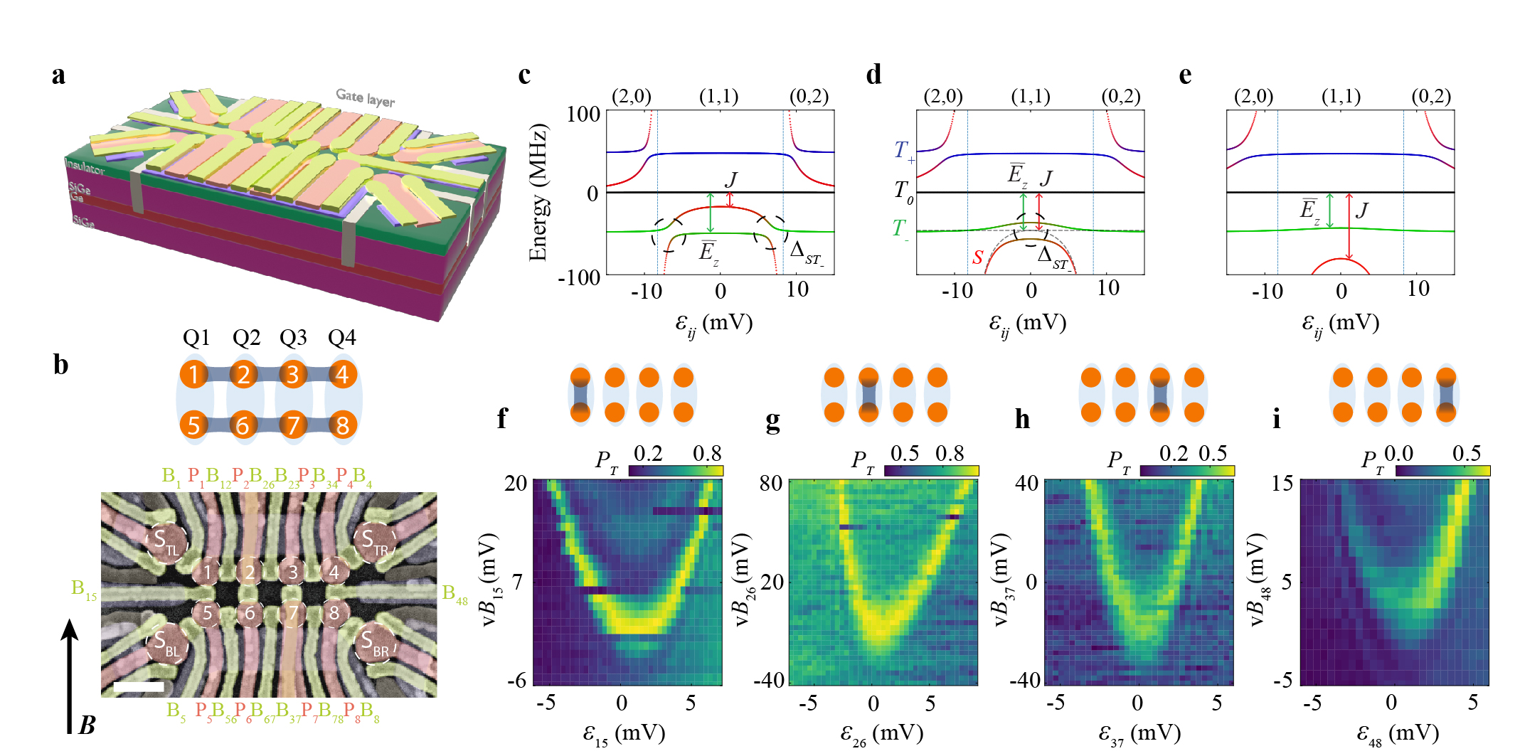
As shown in Fig. 1a and b, the 2x4 quantum dot ladder is fabricated in a germanium quantum-well heterostructure [50]. The gate pattern and substrate have the same design as that in ref. [38]. The eight quantum dots are labeled with numbers 1 to 8 and the four charge sensors to measure the charge states in the quantum dots are labeled , , and , respectively. The quantum dot potentials are controlled by plunger gates , and the interdot or dot-sensor tunnel couplings are controlled by barrier gates or , with or denoting the corresponding quantum dot number. Linear combinations of plunger gate voltages allow us to set the overall electrochemical potential of each DQD and the interdot detuning . The prefix “v” indicates that the physical gate voltages are virtualized to compensate the crosstalk on the dot potentials [16] (see Supplementary Information section III for the virtual gate matrix). Single-hole occupation of each quantum dot in the array is confirmed by measuring the charge stability diagrams using sensors and (see Supplementary Information section II). All plunger and interdot barrier gates are connected to a bias tee to allow both DC voltages and voltage pulses to be applied.
II Singlet-triplet qubit and energy spectroscopy

We encode the qubit into the two-spin singlet-triplet states, and , of the DQDs along the rungs of the quantum dot ladder, with the singlet and the lowest-energy triplet . Thus Q1, Q2, Q3 and Q4 are formed using DQD 1-5, 2-6, 3-7 and 4-8. Qubit readout is achieved by pulsing the corresponding DQD to the PSB regime. This regime converts the singlet and triplet states into distinct charge states, which are then measured through the charge sensor. The single-qubit Hamiltonian can be written as
| (1) |
where and are the Pauli matrices, is a function of both the detuning and the barrier gate voltage , and is the average Zeeman energy of the two hole spins in the DQD, with the average -factor, the Bohr magneton, and the magnetic field strength. Unless indicated otherwise, an in-plane magnetic field (up to alignment precision) of mT is applied to the device. The intrinsic spin-orbit interaction for holes in germanium couples the states and with an energy .
Figs. 1c-e show the energy levels of the two-spin and states in a DQD with , , , respectively. The other two-spin states are and . In a DQD, we can describe the charge states as (,) to denote the charge number distribution in the left () and right () quantum dot. By adjusting the detuning of the DQD from negative to positive, we can change the charge state from (2,0) to (1,1) and then to (0,2), as indicated by the labels on top of each diagram, and the energy levels of the two-spin states in the DQD will change accordingly. As shown in Fig. 1c, when is smaller than , the singlet crosses the triplet twice in the (1,1) regime. Due to intrinsic spin-orbit coupling, these are in fact avoided crossings with a gap , where the states and are admixed. As increases, the two anticrossings approach each other and eventually merge into one, as shown in Fig. 1d. When increases even further, see Fig. 1e, and no longer exhibit an anvoided crossing.
Experimentally, we probe the position of the avoided crossings as follows. First, we initialize one of the qubits to a singlet by diabatically pulsing from (0,2) or (2,0) to the detuning in (1,1). After waiting for a certain time, we pulse the qubit back to the PSB regime to record the triplet probability. When the pulse takes the system to an anticrossing, the singlet will evolve into a triplet during the waiting time (a 40 ns duration is chosen to obtain a sizable triplet probability). Performing such measurements as a function of the barrier gate voltage that controls for each qubit, results in the parabola-like patterns, also called spin mixing maps [51, 22], in Fig. 1f-i. As expected, when is tuned from positive to negative, increases and the positions of the anticrossings move inwards before disappearing. The asymmetry visible in panel g in particular can arise from imperfect virtualization of the barrier gates or from a detuning-dependent Zeeman energy [52] (see Supplementary Information section IV).
III Universal single-qubit control
With the knowledge of the energy spectrum of the four qubits, we next implement the two-axis control of each qubit, which is necessary and sufficient for universal single-qubit control. By operating the qubit in the regime where , the first term of Eq. 1 goes to zero and rotates the qubit around the -axis in the Bloch sphere, as shown in Fig. 2a. Furthermore, we tune the barrier voltage to obtain at zero detuning, which is a symmetry point where the effect of detuning noise is strongly suppressed [53, 54]. The pulse scheme for testing -axis control is shown in Fig. 2k: first we initialize the qubit into a singlet by starting in the (2,0) (or (0,2)) regime, then pulse the detuning to the center of the (1,1) regime where , next allow the qubit to evolve for a variable time , and finally pulse the detuning back to a point in the (2,0) (or (0,2)) regime for spin readout via PSB. The measured rotations of Q1-Q4 as a function of the pulsed detuning position are shown in Fig. 2c-f. With proper calibration, the qubits rotate around the -axis at zero detuning (this condition occurs slightly away from the point extracted from charge stability diagrams).
To realize -axis control, we operate the Hamiltonian in the opposite limit where we increase to such a large value that the effect of spin-orbit coupling becomes negligible. As a result, the qubit is rotated around an axis close to the -axis, with a frequency proportional to . The rotation is never exactly around the -axis due to the presence of a finite , yet, sufficiently orthogonal control is possible when (furthermore, by finely tuning the magnet field direction, can be achievable [49, 46]). In experiments, we perform a Ramsey-like pulse sequence to demonstrate -axis control. As illustrated in Fig. 2b and l, we first initialize the qubit into a singlet, perform a rotation around the -axis of duration , and then change diabatically by pulsing the corresponding barrier gate by an amount to implement a -axis rotation. Throughout the barrier gate pulse, we aim to stay at the symmetry point to minimize the sensitivity to charge noise [53, 54]. Finally, we perform another operation around the -axis and project the qubit into the basis for spin readout.
The measured -axis rotations as a function of the change of barrier voltage for the four qubits are shown in Fig. 2g-j. The oscillation frequency is given by , where is Planck’s constant. Fig. 2n summarizes how can be tuned via . We note that the outer two barrier gates and have a stronger effect on the corresponding than the inner barrier gates and . This may be explained by additional residues below the inner barrier gates, which are fabricated in the last step [38], and by the different fan-out routing for the outer barrier gates (see Fig. 1a,b). With the tuning range shown in panel n, the highest ratio amounts to around 20 for the outer qubits Q1 and Q4 and about 10 for the inner qubits Q2 and Q3. When the external magnetic field strength is varied while keeping the gate voltages fixed, the oscillation speed increases linearly with the field due to the contribution from Zeeman energy in (see Fig. 2m). From the slope, we extract for the four qubits, obtaining values of 0.33(1) - 0.37(1), similar to previous devices [10].
The dephasing time under free evolution, which is traditionally termed , is an important metric for assessing the qubit quality. Since the qubit rotations around both the -axis and the -axis are the result of free evolution, we here introduce and to describe the corresponding dephasing times. Fig. 2o,p show the measured damped oscillations of the qubits under -axis and -axis control, to which we fit with a function . , , , , are fitting parameters, where refers to the oscillation frequency and refers to or . From the fits, we obtain a of 0.5 - 2.1 s and a of 42(5) - 147(31) ns. The measured values of are slightly lower than previously reported values measured at mT [19] under the same condition that is parallel to the hole movement direction. This can be partly attributed to the larger magnetic field in the present experiment: scales with [44, 45] and not only sets but also constitutes a proportionality factor between noise and fluctuations (see also Supplementary Information section VIII). The extracted -axis rotation frequencies in Fig. 2o reflect the values of for each qubit, which are around 11.9-15.9 MHz, nearly an order of magnitude larger than the results reported at mT [19]. This confirms that is stronger in the present experiment than in the previous work at 3 mT. The small variation in and in the measured average -factors suggests a homogeneous spin-orbit coupling in this device. In comparison, the variations in are quite large, which may be caused by spatially dependent charge noise or inhomogeneous hyperfine-induced dephasing due to dot size differences [55].
We also observe that is nearly an order of magnitude smaller than . Possibly this is due to the fact that fluctuations in the tunnel barrier translate to fluctuations in , which couple in directly during -axis evolution but only to second order for -axis evolution [56, 57]. Additionally, the increased curvature of the singlet branch for larger implies a higher sensitivity to detuning noise. The variations in thus may contribute to the spread of the values we obtained in Fig. 2p.
IV Two-qubit gate
In order to realize universal control of the full four-qubit register, we need to complement single-qubit gates with two-qubit entangling gates. Assuming isotropic exchange interactions between adjacent qubits, the two-qubit Hamiltonian in the basis of , , and can be written as:
| (2) |
where and refer to the respective qubit dot pair, and the interqubit coupling . The coupling term is reminiscent of two well-known interaction Hamiltonians. If the factor of the coupling term were 1 instead, we recover the exchange Hamiltonian that generates the SWAP gate and the universal gate. If that factor were zero, only the flip-flop terms would survive, which generate the iSWAP and gate. The coupling Hamiltonian in Eq. 2 thus generates a SWAP-style gate that is not a standard two-qubit gate but is also universal from the perspective of quantum computing (see Supplementary Information section VIII). For simplicity, we call it a SWAP gate in the remainder of this work.
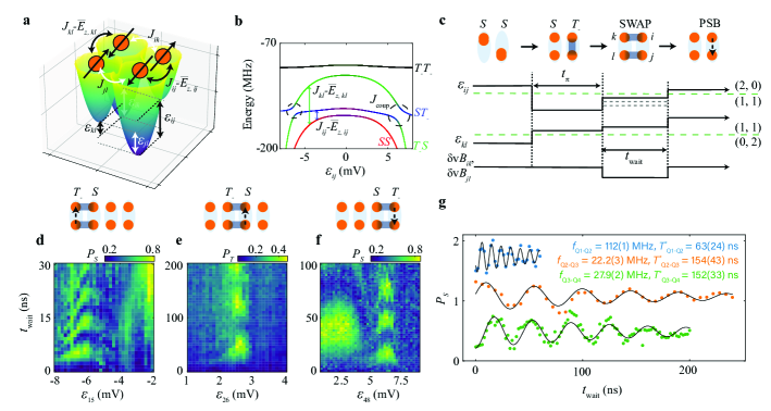
To activate the SWAP gate, we equalize the energy splittings of two qubits and turn on and such that the flip-flop terms can exchange the qubit populations (note that if the qubit energies were set very different from each other, a CZ gate would result instead). Our strategy for meeting both requirements at the same time is to use the interdot detuning of both qubits [18, 19]. A typical potential landscape for the two qubits in DQD and is shown in Fig. 3a, where we pulse to large positive and to large negative detuning. The detunings and , which control the interactions between the qubits, are then automatically increased as well. Therefore, all the exchange interactions involved are enhanced simultaneously and the effect of the single-qubit terms is made negligible. In practice, we fix the (large) detuning of one qubit and fine-tune that of the other to find the position where two qubits have equal energy splittings. This is illustrated by the energy spectrum in Fig. 3b, where we fix the detuning to a large negative value and scan the detuning . We see that the states and anticross at the two positions where is equal to . The gap size is given by . Since and , which control via and , are also dependent on , the sizes of the two gaps are not necessarily the same.
Fig. 3c shows an example of the pulse scheme we use in the experiment to observe two-qubit SWAP oscillations. Starting from both qubits in (0,2) or (2,0), we initialize one qubit to using single-qubit control by pulsing to zero and waiting for a rotation, and we initialize the other qubit to by pulsing to a large value in (1,1) (other qubits are either initialized to singlets by pulsing back and forth to (0,2) or (2,0), or remain in the (1,1) regime all the time). Then we pulse the detuning of one qubit such that the energies of the two qubits match, and SWAP oscillations are initiated. Simultaneously, several barrier voltages are pulsed to help set the respective exchange-interaction strengths to appropriate values (details of these pulses vary).
Fig. 3d-f show the resulting SWAP oscillations for Q1-Q2, Q2-Q3, and Q3-Q4. Chevron-style patterns are observed with the energies of the two qubits aligned in the middle of the patterns. Moving away from the middle, the energy of one qubit is shifted with respect to that of the other. This qubit-qubit energy detuning tilts the rotation axis and accelerates the rotation. Looking closely, the chevron patterns are not symmetrical. This can be understood by the fact that the qubit energy does not vary linearly with detuning. In some panels, single-qubit oscillations around an axis close to the -axis are also observed, such as the data at mV in Fig. 3d and that at mV in Fig. 3f. These values are close to zero interdot detuning, and when is not much larger than , such rotations are expected. We note that SWAP oscillations between and were also observed in previous research on simulating the dynamics of an antiferromagnetic spin chain and resonating-valence-bond states based on the Heisenberg model in four-quantum-dot systems [18, 19].
The oscillation frequencies in the middle of the chevron patterns are in the range of 22.2(3) - 112(1) MHz, corresponding to a (entangling) gate with durations of just 2.2 ns to 11.3 ns, more than an order of magnitude faster than the entangling gate based on capacitive coupling [13, 14]. To determine the dephasing times of the SWAP oscillations, we collect data in the middle of the chevron patterns, as shown in Fig. 3g, and fit them with the same function as used for single-qubit oscillations. The extracted dephasing times are between 63(24) and 154(43) ns. The dephasing times may be further increased by executing the SWAP oscillations at the symmetry points of the detuning of each qubit, which requires a stronger tunability of the exchange interactions using the barrier gates.
V Quantum circuit implementation
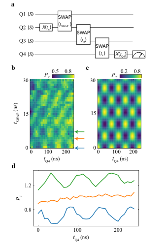
Finally, using a combination of the single- and two-qubit gates demonstrated above, we aim to implement a quantum circuit designed to create and distribute an entangled state. As shown in Fig. 4a, we first initialize Q1 and Q2 into by applying a rotation on Q2 and then activate a SWAP interaction between Q1 and Q2 for a duration . This interaction is expected to generate entanglement when corresponds to a quarter period, i.e. for a gate. Next, we apply consecutive half-period SWAP gates of Q2-Q3 and Q3-Q4 to transfer the state of Q2 to Q4 via Q3. Finally, we perform a single-qubit -axis rotation of Q4 for a time and measure Q4.
The experimental results are shown in Fig. 4b, where the single-qubit oscillations of Q4 as a function of are modulated in phase by , resulting in a checkerboard pattern. The underlying mechanism is that the state of Q2 oscillates as a function of , as quantum information is periodically exchanged between Q1 and Q2. Therefore the state of Q4 following the quantum state transfer also oscillates with . Where the evolution of Q4 changes phase, corresponds to the duration of a operation (modulo an integer number of SWAP operations), at which point maximal entanglement between Q1 and Q2 is expected. When two qubits are maximally entangled, the density matrix of each qubit by itself is fully mixed. At this point, the measured of Q4 should not oscillate as a function of . This is indeed what we observe, see Fig. 4d, where we show the linecuts from Fig. 4b. A trace without oscillations is observed between two sets of out-of-phase oscillations of Q4, as expected. The same features are seen in Fig. 4c, which shows the ideally expected checkerboard pattern obtained from numerical simulations of the protocol of Fig. 4a, assuming perfect initialization, operations and readout.
We note the checkerboard pattern is quite robust to errors in the SWAP gates. Small errors will merely change the contrast of the pattern; for large SWAP errors, the alternating rows are no longer equal in height. However, when the initialization of Q1 or Q2 leads to superposition states with a -axis component (and assuming perfect SWAP gates), the pattern acquires a tilt. In this case, the rotation angle of the final -axis rotation needed to maximize or minimize is no longer exactly or but depends on the -axis component of Q4 (and hence also on ) after the sequence of SWAP operations. Looking closely, the blue and green oscillations in Fig. 4d are not perfectly out of phase with each other, and the data in Fig. 4b shows weak diagonal features not seen in the numerical simulations. These point at the imperfect initialization of Q1 or Q2.
VI Conclusion
In conclusion, we have experimentally demonstrated initialization, readout, and universal control of four singlet-triplet () qubits in a 2x4 germanium quantum dot array. The intrinsic spin-orbit coupling in germanium combined with tunnel barrier control of the exchange interactions within each qubit, allows us to realize two-axis control of the four individual qubits using baseband signals only. Furthermore, through independent control of the exchange interactions between any pair of neighbouring spins across the device, we are able to demonstrate and SWAP gates for each neighboring pair of qubits and implement a quantum circuit that spans the entire array. With four universally controlled qubits in a bilinear array, these results put baseband-controlled singlet-triplet spin qubits in germanium firmly on the map as a potential candidate for large-scale quantum computing.
In future experiments, the control fidelities and error channels of these qubits can be thoroughly characterized by various metrology methods such as randomized benchmarking and gate set tomography [7, 15]. The qubit quality and control fidelity can be potentially improved by tuning the qubits into the operational sweet spot with respect to the electric field or magnetic field [58, 59, 55], optimizing control pulses [28, 47], reducing charge noise [60], further improvements in the Ge/SiGe heterostructure [61, 62], and suppressing nuclear spin noise using substrates with reduced spinful nuclei [41]. Moreover, with programmable control of exchange interactions in the array, this spin ladder can also be used for analog simulation of a wealth of rich physical phenomena such as quantum magnetism [63].
Acknowledgements.
We thank C. Déprez for insightful discussions and kind help. We also thank other members of the Vandersypen group and Veldhorst group for their stimulating discussions. We acknowledge S. L. de Snoo’s help in software development and technical support by O. Benningshof, J. D. Mensingh, R. Schouten, R. Vermeulen, R. Birnholtz, E. Van der Wiel, and N. P. Alberts. This work was funded by an Advanced Grant from the European Research Council (ERC) under the European Union’s Horizon 2020 research. M.R.-R. acknowledges support from the Netherlands Organization of Scientific Research (NWO) under Veni grant VI.Veni.212.223.Author contributions X.Z. and E.M. performed the experiment and analyzed the data with help from M.R.-R. and D.J.. X.Z. performed the numerical simulations with help from M.R.-R. and D.J.. M.R-R developed the theory model. T.-K.H., P.C.F. and C.-A.W. contributed to the preparation of the experiments. S.D.O. fabricated the device with inputs from T.-K.H., P.C.F. and X.Z.. A.S. grew the Ge/SiGe heterostructure, M.V. supervised the device fabrication and G.S. supervised the heterostructure growth and development. X.Z. and L.M.K.V. conceived the project and L.M.K.V. supervised the project. X.Z., M.R.-R., E.M. and L.M.K.V. wrote the manuscript with inputs from all authors.
Data availibility The data reported in this paper are archived on a Zenodo data repository at https://doi.org/10.5281/zenodo.10431402
References
- [1] Vandersypen, L. et al. Interfacing spin qubits in quantum dots and donors—hot, dense, and coherent. npj Quantum Inf. 3, 34 (2017).
- [2] Heinrich, A. J. et al. Quantum-coherent nanoscience. Nat. Nanotechnol. 16, 1318–1329 (2021).
- [3] Gonzalez-Zalba, M. et al. Scaling silicon-based quantum computing using CMOS technology. Nat. Electron. 4, 872–884 (2021).
- [4] Chatterjee, A. et al. Semiconductor qubits in practice. Nat. Rev. Phys. 3, 157–177 (2021).
- [5] Stano, P. & Loss, D. Review of performance metrics of spin qubits in gated semiconducting nanostructures. Nat. Rev. Phys. 4, 672–688 (2022).
- [6] Burkard, G., Ladd, T. D., Pan, A., Nichol, J. M. & Petta, J. R. Semiconductor spin qubits. Rev. Mod. Phys. 95, 025003 (2023).
- [7] Xue, X. et al. Quantum logic with spin qubits crossing the surface code threshold. Nature 601, 343–347 (2022).
- [8] Noiri, A. et al. Fast universal quantum gate above the fault-tolerance threshold in silicon. Nature 601, 338–342 (2022).
- [9] Mills, A. R. et al. Two-qubit silicon quantum processor with operation fidelity exceeding 99%. Sci. Adv. 8, eabn5130 (2022).
- [10] Hendrickx, N. W. et al. A four-qubit germanium quantum processor. Nature 591, 580–585 (2021).
- [11] Philips, S. G. et al. Universal control of a six-qubit quantum processor in silicon. Nature 609, 919–924 (2022).
- [12] Lawrie, W. et al. Simultaneous single-qubit driving of semiconductor spin qubits at the fault-tolerant threshold. Nat. Commun. 14, 3617 (2023).
- [13] Shulman, M. D. et al. Demonstration of entanglement of electrostatically coupled singlet-triplet qubits. Science 336, 202–205 (2012).
- [14] Nichol, J. M. et al. High-fidelity entangling gate for double-quantum-dot spin qubits. npj Quantum Inf. 3, 3 (2017).
- [15] Weinstein, A. J. et al. Universal logic with encoded spin qubits in silicon. Nature 615, 817–822 (2023).
- [16] Hensgens, T. et al. Quantum simulation of a Fermi–Hubbard model using a semiconductor quantum dot array. Nature 548, 70–73 (2017).
- [17] Dehollain, J. P. et al. Nagaoka ferromagnetism observed in a quantum dot plaquette. Nature 579, 528–533 (2020).
- [18] van Diepen, C. J. et al. Quantum simulation of antiferromagnetic Heisenberg chain with gate-defined quantum dots. Phys. Rev. X. 11, 041025 (2021).
- [19] Wang, C.-A. et al. Probing resonating valence bonds on a programmable germanium quantum simulator. npj Quantum Inf. 9, 58 (2023).
- [20] Jang, W. et al. Individual two-axis control of three singlet-triplet qubits in a micromagnet integrated quantum dot array. Appl. Phys. Lett. 117, 234001 (2020).
- [21] Fedele, F. et al. Simultaneous operations in a two-dimensional array of singlet-triplet qubits. PRX Quantum 2, 040306 (2021).
- [22] Mortemousque, P.-A. et al. Coherent control of individual electron spins in a two-dimensional quantum dot array. Nat. Nanotechnol. 16, 296–301 (2021).
- [23] Levy, J. Universal quantum computation with spin- pairs and Heisenberg exchange. Phys. Rev. Lett. 89, 147902 (2002).
- [24] Petta, J. R. et al. Coherent manipulation of coupled electron spins in semiconductor quantum dots. Science 309, 2180–2184 (2005).
- [25] Maune, B. M. et al. Coherent singlet-triplet oscillations in a silicon-based double quantum dot. Nature 481, 344–347 (2012).
- [26] Wu, X. et al. Two-axis control of a singlet–triplet qubit with an integrated micromagnet. Proc. Natl. Acad. Sci. U.S.A. 111, 11938–11942 (2014).
- [27] Jock, R. M. et al. A silicon metal-oxide-semiconductor electron spin-orbit qubit. Nat. Commun. 9, 1768 (2018).
- [28] Cerfontaine, P. et al. Closed-loop control of a GaAs-based singlet-triplet spin qubit with 99.5% gate fidelity and low leakage. Nat. Commun. 11, 4144 (2020).
- [29] Cerfontaine, P., Otten, R., Wolfe, M., Bethke, P. & Bluhm, H. High-fidelity gate set for exchange-coupled singlet-triplet qubits. Phys. Rev. B 101, 155311 (2020).
- [30] Jirovec, D. et al. A singlet-triplet hole spin qubit in planar Ge. Nat. Mater. 20, 1106–1112 (2021).
- [31] Takeda, K. et al. Optimized electrical control of a Si/SiGe spin qubit in the presence of an induced frequency shift. npj Quantum Inf. 4, 54 (2018).
- [32] Undseth, B. et al. Hotter is easier: Unexpected temperature dependence of spin qubit frequencies. Phys. Rev. X 13, 041015 (2023).
- [33] Undseth, B. et al. Nonlinear response and crosstalk of electrically driven silicon spin qubits. Phys. Rev. Appl. 19, 044078 (2023).
- [34] Ono, K., Austing, D., Tokura, Y. & Tarucha, S. Current rectification by pauli exclusion in a weakly coupled double quantum dot system. Science 297, 1313–1317 (2002).
- [35] Qiao, H. et al. Floquet-enhanced spin swaps. Nat. Commun. 12, 2142 (2021).
- [36] Chanrion, E. et al. Charge detection in an array of CMOS quantum dots. Phys. Rev. Appl. 14, 024066 (2020).
- [37] Duan, J. et al. Remote capacitive sensing in two-dimensional quantum-dot arrays. Nano Lett. 20, 7123–7128 (2020).
- [38] Hsiao, T. K. et al. Exciton transport in a germanium quantum dot ladder. arXiv preprint arXiv:2307.02401 (2023).
- [39] Borsoi, F. et al. Shared control of a 16 semiconductor quantum dot crossbar array. Nat. Nanotechnol. 1–7 (2023).
- [40] Neyens, S. et al. Probing single electrons across 300 mm spin qubit wafers. arXiv preprint arXiv:2307.04812 (2023).
- [41] Scappucci, G. et al. The germanium quantum information route. Nat. Rev. Mater. 6, 926–943 (2021).
- [42] Petta, J., Lu, H. & Gossard, A. A coherent beam splitter for electronic spin states. Science 327, 669–672 (2010).
- [43] Ribeiro, H., Petta, J. R. & Burkard, G. Harnessing the GaAs quantum dot nuclear spin bath for quantum control. Phys. Rev. B 82, 115445 (2010).
- [44] Nichol, J. M. et al. Quenching of dynamic nuclear polarization by spin-orbit coupling in GaAs quantum dots. Nat. Commun. 6, 7682 (2015).
- [45] Jirovec, D. et al. Dynamics of hole singlet-triplet qubits with large -factor differences. Phys. Rev. Lett. 128, 126803 (2022).
- [46] Mutter, P. M. & Burkard, G. All-electrical control of hole singlet-triplet spin qubits at low-leakage points. Phys. Rev. B 104, 195421 (2021).
- [47] Fernández-Fernández, D., Ban, Y. & Platero, G. Quantum control of hole spin qubits in double quantum dots. Phys. Rev. Appl. 18, 054090 (2022).
- [48] Cai, X., Connors, E. J., Edge, L. F. & Nichol, J. M. Coherent spin–valley oscillations in silicon. Nature Physics 19, 386–393 (2023).
- [49] Rooney, J. et al. Gate modulation of the hole singlet-triplet qubit frequency in germanium. arXiv preprint arXiv:2311.10188 (2023).
- [50] Lodari, M. et al. Low percolation density and charge noise with holes in germanium. Mater. Quantum Technol. 1, 011002 (2021).
- [51] Bertrand, B. et al. Quantum manipulation of two-electron spin states in isolated double quantum dots. Phys. Rev. Lett. 115, 096801 (2015).
- [52] Hendrickx, N. et al. A single-hole spin qubit. Nat. Commun. 11, 3478 (2020).
- [53] Martins, F. et al. Noise suppression using symmetric exchange gates in spin qubits. Phys. Rev. Lett. 116, 116801 (2016).
- [54] Reed, M. D. et al. Reduced sensitivity to charge noise in semiconductor spin qubits via symmetric operation. Phys. Rev. Lett. 116, 110402 (2016).
- [55] Hendrickx, N. et al. Sweet-spot operation of a germanium hole spin qubit with highly anisotropic noise sensitivity. arXiv preprint arXiv:2305.13150 (2023).
- [56] Hu, X. & Das Sarma, S. Charge-fluctuation-induced dephasing of exchange-coupled spin qubits. Phys. Rev. Lett. 96, 100501 (2006).
- [57] Huang, P., Zimmerman, N. M. & Bryant, G. W. Spin decoherence in a two-qubit CPHASE gate: the critical role of tunneling noise. npj Quantum Inf. 4, 62 (2018).
- [58] Wang, Z. et al. Optimal operation points for ultrafast, highly coherent Ge hole spin-orbit qubits. npj Quantum Inf. 7, 54 (2021).
- [59] Wang, C.-A., Scappucci, G., Veldhorst, M. & Russ, M. Modelling of planar germanium hole qubits in electric and magnetic fields. arXiv preprint arXiv:2208.04795 (2022).
- [60] Massai, L. et al. Impact of interface traps on charge noise, mobility and percolation density in Ge/SiGe heterostructures. arXiv preprint arXiv:2310.05902 (2023).
- [61] Lodari, M. et al. Lightly strained germanium quantum wells with hole mobility exceeding one million. Appl. Phys. Lett. 120 (2022).
- [62] Stehouwer, L. E. et al. Germanium wafers for strained quantum wells with low disorder. Appl. Phys. Lett. 123 (2023).
- [63] Dagotto, E. & Rice, T. Surprises on the way from one-to two-dimensional quantum magnets: The ladder materials. Science 271, 618–623 (1996).