Sheng Jiang 33institutetext: School of Microelectronics, South China University of Technology, 511442 Guangzhou, Chinas
Sunjae Chung 44institutetext: Department of Physics Education, Korea National University of Education, Cheongju 28173, Korea
Johan Åkerman* 55institutetext: Department of Physics, University of Gothenburg, 41296, Gothenburg, Sweden, and also with Research Institute of Electrical Communication (RIEC) and Center for Science and Innovation in Spintronics (CSIS), Tohoku University, 2-1-1 Katahira, Aoba-ku, Sendai 980-8577 Japan.
(*e-mail: johan.akerman@physics.gu.se)
Magnetic droplet solitons
Abstract
Magnetic droplets are nanoscale, non-topological, dynamical solitons that can be nucleated in different spintronic devices, such as spin torque nano-oscillators (STNOs) and spin Hall nano-oscillators (SHNOs). This chapter first briefly discusses the theory of spin current driven dissipative magnetic droplets in ferromagnetic thin films with uniaxial anisotropy. We then thoroughly review the research literature on magnetic droplets and their salient features, as measured using electrical, microwave, and synchrotron techniques, and as envisaged by micromagnetic simulations. We also touch upon a closely related soliton, the dynamical skyrmion. Finally, we present an outlook of new routes in droplet science.
1 Introduction
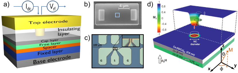
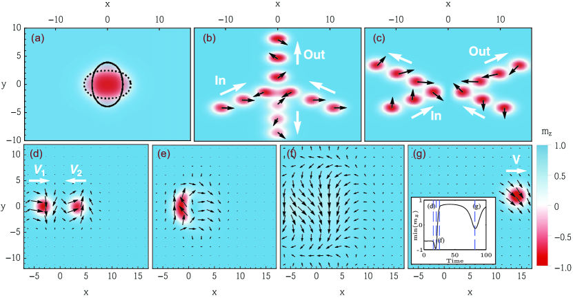
A soliton is a localized and particle-like wave that preserves its shape and is robust against perturbations. Solitons are found in a large variety of systems, but share vital elements such as self-organization through a balance of strong non-linearity and dispersion in the medium. Purwins2010 Solitons were first described by John Scott Russell in 1834 as he observed remarkably stable waves in the Union Canal in Scotland, which traveled for miles without losing their shape. The name ”soliton” was coined by Zabusky and Kruskal who found localized, self-reinforcing, and highly stable propagating solutions to the Korteweg-de Vries (KdV) equation. Magnetodynamical solitons111There exists another class of static solitons that are topological. They are topological particle-like objects in ordered states of matter, which cannot be smoothed out through continuous transformation of the order parameter. In magnetism, they are e.g. represented by the domain wall, the vortex, the skyrmion, and other topological objects. As our chapter treats magnetodynamical solitons, we will not further discuss static solitons. have been theoretically studied for over 40 years, with many erly important results Ivanov1989 ; Kosevich1981 ; Kosevich1990 ; Bespyatykh1994 . Conservative solitons (zero damping) in perpendicular anisotropy magnets were analyzed and termed “magnon drops”, in an analogy of a gas compared to a drop of quasi-particles (”free” versus condensed magnons). Ivanov1976 ; Ivanov1977 However, the envisaged phenomenon was never experimentally realized due to the detrimental effect of magnetic damping. Micromagnetic simulations, where the anti-damping effect of spin transfer torque (STT) Hoefer2010 was used to cancel the damping locally, suggested that spin torque nano-oscillators (STNOs) should be able to sustain a so-called magnetic droplet. This paved the way for the first experimental demonstrations of magnetic droplets, published as late as 2013 Mohseni2013a . The distinction “droplet” in contrast to “drop”, was made to emphasize the strongly dissipative nature of the STT-stabilized soliton. The archetype device hosting droplets, the STNO, is outlined in Fig. 1a)–c) together with an illustration of the droplet itself (Fig. 1d)). Since its discovery, this distinctive soliton has continued to attract interest, both from fundamental and application-driven perspectives. While many early aspects of magnetic droplets have been covered by previous reviews on the topic Sulymenko2018ltp ; Macia2020 ; Chung2015 ; Akerman2018 , and can be used as a complement to this chapter, a number of very recently demonstrated novel droplet phenomena are here summarized for the first time.
In this chapter we give a thorough description of the droplet, starting with the initial prediction, realization, and verification. We continue with the details of generation, inherent dynamics, and means to control and maneuver the droplet. The final subsections portray complementary devices and resemblant solitons. Taken together, the content serves as a valuable introduction to the curious reader, as well as a comprehensible overview of the field.
2 Pioneer Studies
2.1 Theoretical Prediction
Spin wave drops, i.e. particle-like magnon condensates, were predicted in Ref. Ivanov1977 ; Ivanov1989 ; Ivanov1976 for the conservative case, i.e. in the absence of damping. The simplest system where an attraction between magnons can be realized is a uniaxial ferromagnet with easy-axis anisotropy (in the form ) and an external field along the anisotropy axis. Thin films with sufficiently strong perpendicular magnetic anisotropy (PMA) to overcome the demagnetizing field are examples of such systems. In this geometry, magnons experience an attractive force and can condense into drops.
We define as the polar angle between the easy-axis and the magnetization, while is the azimuthal angle in the film plane (see Fig. 1c). Throughout the drop, the azimuthal angle of all its spins varies linearly in time as , with lying between the Zeeman frequency and the ferromagnetic resonance (FMR): . The polar angle is both azimuthally symmetric and independent on time , and, hence, at every point, the magnetization precesses with the same phase and with a radially dependent cone angle. The precession frequency and the radial profile are strongly connected and depend on the number of magnons in the condensate. Close to FMR, the soliton profile is quite narrow and the angle at the center is small, i.e. the drop is not yet reversed. However, as more magnons condense, the frequency decreases and grows towards the limit value of a reversed core (), and the drop and its profile expand. Thus, for low droplet frequencies, there is a substantial area at the core of the drop where the magnetization is reversed. The profile of the drop satisfies a balance between exchange and anisotropy. Similar to a domain wall, the exchange length () defines the width of the transition region between the reversed core and the surroundings aligned with the field.
A dissipative magnetic droplet is closely related to the magnon drop and inherits most of its general properties. A droplet can exist in a magnetic medium with damping, as long as there is an energy source available to sustain it. In spin torque nano-oscillators, the droplet is nucleated and sustained by spin transfer torque (STT) provided by a spin-polarized current through a nano-contact. The theory for such magnetic droplets in STNOs was developed in a seminal paper from 2010 by Hoefer, Silva, and Keller Hoefer2010 . In addition to the magnon drop’s balance between exchange and anisotropy, a droplet also requires a balance between magnetic losses in the form of Gilbert damping and the energy gain provided by the STT. This additional condition selects a certain frequency and thereby the profile of the droplet, as well as a minimum sustaining current. In a fully symmetric system described by rescaled, dimensionless units, the sustaining droplet current is given solely by the nanocontact (NC) radius, apart from a weak influence of the spin torque asymmetry (). The NC radius also sets the maximum frequency, the core reversal, and the size of the droplet. Thus, in contrast to the conservative case, where the drop can be of any size, the dissipative droplet is mostly limited by the size of the NC. Smaller droplets exhibit higher frequencies and less core reversal.
The symmetry is broken by the Oersted field, which shifts the droplet position off-center, leads to spatial magnetic phase variations, and induces a minor frequency drop. A canted applied field, and/or a canted reference layer magnetization, also breaks the symmetry. These three perturbations together can trigger the droplet to escape the NC. This so-called drift instability is reviewed in Sec. 5.2 below.
2.2 First Experiments
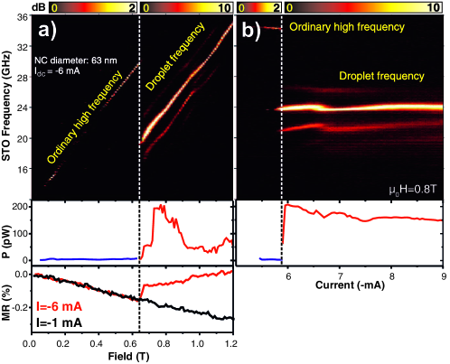
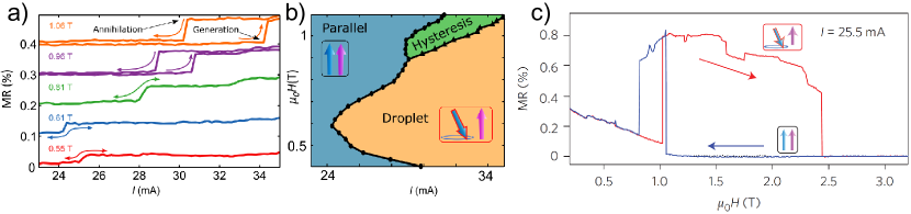
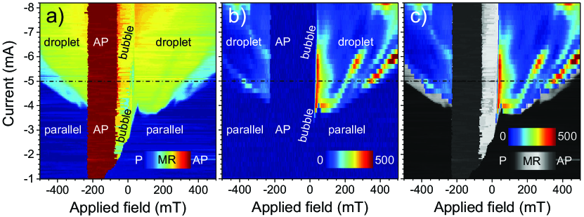
Three years after the theoretical prediction, Mohseni et al. reported the first experimental demonstration of a magnetic droplet soliton Mohseni2013a . The authors used orthogonal STNOs, with an out-of-plane (OOP) anisotropy Co/Ni-multilayer as the free layer (FL) and in-plane anisotropy Co as the reference layer (RL). The experimental signature of droplet nucleation is remarkably distinct. Figure 2(a) shows how the power spectral density (PSD), the signal power, and the magnetoresistance (MR) evolve with applied field (). Below T, a weak high-frequency signal is observed, and the MR decreases linearly as the free and fixed layers become more parallel. Then, at the threshold field, all measured parameters change drastically. The signal frequency drops by 10.3 GHz, the power rises substantially, and the magnetoresistance increases abruptly and its slope reverses sign. Likewise, with increasing current the same type of changes are observed above the critical nucleation current, as illustrated in Fig. 2(b). These measured characteristics align with the theoretical predictions of the droplet state Hoefer2010 . Simply put, this abrupt threshold is the experimental fingerprint of droplet formation.
Another confirmed theoretical prediction was the hysteresis in sustaining current. A lower current is needed to sustain an existing droplet, compared to the initial nucleation current. Thus, there is an energy barrier separating the droplet state from the parallel state.
The nucleation of a droplet, and its general field dependence, were reproducible from device to device. However, additional sidebands of the main frequency (Fig. 2 top) were only observed in some devices. Simulations reveal that the sidebands originate from auto-modulation and drift instabilities more sensitive to device-to-device variations, which are topics covered in Sec. 5.3 and 5.2.
The authors argued that the nucleation current () should predominantly be driven by the perpendicular component of the polarized spin current, which is directly proportional to the magnitude of the out-of-plane magnetization of the reference layer (). The higher the OOP applied field, the higher the , and the lower the nucleation current, . This relation is indeed observed for low fields ( of the reference layer saturation field ()). Later studies have shown that this is only half of the story, see below and Sec. 4.1.
After the first demonstration, another independent experimental study of magnetic droplets was reported by Macià et al. Macia2014 . This paper explores the droplet evolution using detailed MR measurements at low temperatures (4.2 K). Again, orthogonal STNOs was used, but here permalloy served as the reference layer. The droplet state was recognized by the characteristic abrupt drop in frequency at the nucleation current, and the presence of an energy barrier for droplet formation was verified by current sweeps showing hysteresis. Notably, no hysteresis was found at low fields, and the hysteresis area increased with the applied out-of-plane field.
The MR showed an excellent signal-to-noise ratio, which allowed the identification of spin wave (SW) excitations, preexisting the droplet at lower currents. Furthermore, the maximum expected MR (assuming a full free layer reversal beneath the nanocontact) was calculated and compared to the measured step at droplet nucleation. The measured MR was consistently lower than the maximum MR for fields below the reference layer saturating field. As the applied field becomes high enough to saturate the fixed layer out-of-plane, the difference between measured and calculated MR almost vanished, leaving a 5% deviation. The result confirmed that the droplet core is essentially fully reversed compared to the surrounding magnetization.
This study also examined the field dependence of the nucleation current. Contrary to the findings in Ref. Mohseni2013a , they found a linear trend, which they could fit using a macrospin model. However, the two reports focus on different field ranges: Mohseni et al. Mohseni2013a reported on the low field limit, while Macià et al. Macia2014 considered fields above .
3 Direct Observation
The first experimental droplet studies yielded results in good agreement with the theory, which were also corroborated by micromagnetic simulations. However, it was still possible to argue that there were weaknesses in the experimental approach – all measurements were indirect. The final piece of evidence was missing. To confirm the existence of the dissipative droplet soliton, a direct observation, an image, was needed.
The droplet radius is only about 100 nm and few imaging techniques are available that provide the required resolution. Scanning transmission X-ray microscopy (STXM) is one of them, and it can also measure very small changes in magnetization, down to , as well as an element selective contrast Bonetti2015 ; Macia2012 . Using this method, the first successful direct observation a droplet was made in 2015 by Backes et al. Backes2015 . They detected a magnetic contrast, which clearly corresponded to a decrease in and only appeared above a threshold current (see Fig. 3(a)). Furthermore, they were able to confirm that a soliton indeed forms under the nanocontact (NC) by comparing the spin wave excitation profile with calculated predictions. The measured envelope was consistent with a droplet, while propagating SWs could be discarded. As expected, the full-width-half-maximum of the reversed magnetic area matched the NC diameter. Yet, the observed of reversal was far from the inferred earlier from magnetoresistance measurements. The origin of this discrepancy lies in the droplet drift instabilities caused by temperature fluctuations and/or a non-saturated fixed layer. During the 60–90 minutes it takes to acquire one image, the droplet may have moved around and even annihilated/re-nucleated. Thus, the final image represented a time average and displayed a mean value rather than an instantaneous picture of a fully developed droplet.
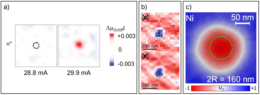
Another study used holography combined with extended reference autocorrelation by linear differential operator (HERALDO) Guizar2007 ; Guizar2008 in an attempt to image a droplet Burgos2018 . As in STXM, the magnetic contrast is given by X-ray magnetic circular dichroism (XMCD) Thole1992 ; Chen1995 . The paper reports on the evolution of the domain pattern in the free layer with applied field and current. However, while holography should enable single-shot images, only time-averaged results are presented in the paper, likely to enhance the signal-to-noise ratio. The authors detected a droplet-like feature for a single experimental setting. The image is presented in Fig. 3(b). The discrepancies between a well-defined circular perimeter and the observed deformed structure were attributed to the time-averaging of the moving droplet. Hence, an experimental image of a stable droplet, which could be compared to simulations, was still lacking in the literature.
Finally, in 2018, the first direct image of a fully reversed magnetic droplet soliton was published (Fig. 3(c)) Chung2018PRL . To the authors’ surprise, the droplet was twice as big as the nanocontact. A possible explanation could again be the time-averaging of a droplet moving about the NC. However, theory and simulations predicting a droplet with about the same size as the NC diameter rely on a simplified model of the electrical current distribution within the device, commonly described as just a cylinder. However, more realistic COMSOL calculations revealed that the electrical current also has an in-plane radial component. The in-plane component leads to a lateral spin-torque, known as Zhang-Li torque (ZLT), which could account for the droplet enlargement. Further evidence was given by electrical measurements, which showed that the effect was reversed upon reversing the sign of the current and thereby ZLT. In the anti-parallel state, a droplet is nucleated by a positive current and this droplet is instead compressed compared to the parallel state droplet. The unveiled importance of the lateral torque inspired a subsequent report on broader effects of ZLT on different modes in spin-torque nano-oscillators. Albert2020
4 Generation and Annihilation
4.1 Nucleation Boundaries
Droplets form when the applied current generates sufficient spin torque to overcome the magnetic damping in a material with large perpendicular anisotropy. For an all-perpendicular system, ignoring perturbations such as the Oersted field (), the PMA-to-exchange balance decides the droplet frequency. The nucleation current () is a function of this frequency, which increases linearly with applied field. Hoefer2010 . Hence, in the simplest approximation, should only depend on material parameters of the free layer and be directly proportional to , as long as the STT overcomes the damping.
On the other hand, one can also describe droplet nucleation as a consequence of the Slonczewski mode being modulationally unstable, i.e. propagating spin waves collapse into a localized soliton Hoefer2010 ; Chung2016 . The primary requirement is accordingly that the applied current exceeds the SW excitation threshold, which is field dependent slonczewski1999jmmm ; Slonczewski2002 . This line of argument leads to a similar conclusion as above, but highlights the role of the STT and thereby the reference layer. For all-perpendicular devices, increases linearly with , which has also been observed experimentally Chung2018PRL , but for orthogonal devices two different field regimes emerge.
We described in Sec. 2.2 how the two pioneering studies concluded on dissimilar equations for . This inconsistency was resolved in a study by Chung et al. Chung2016 . They followed the work by Slonczewski slonczewski1999jmmm and Hoefer Hoefer2010 to derive an equation for the nucleation current:
| (1) |
where is the damping. All three constants 222, 333, and 444 contain material parameters, the NC area, and spin torque coefficients555 is the FL magnetization, is the polarizing RL magnetization, the NC radius, the FL anisotropy field, the FL exchange length, , and , where is the FL thickness, is the elementary charge, the permeability of free space, and the reduced Planck’s constant.. Specifically, and include the spin torque asymmetry () and efficiency (). Equation 1 unites the low and high field regions, taking into account both spin wave stiffening () and reference layer saturation ().
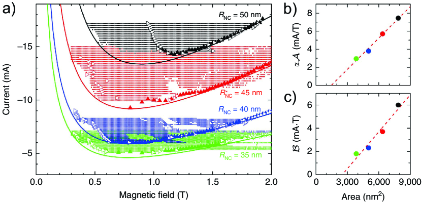
Moreover, their report includes a large compilation of nucleation field/current values, using four different NC radii. The result is found in Fig. 4(a) together with fits to Eq. 1. The dotted areas illustrate regions where the low-frequency noise exceeds 0.3 pW. Figures 4(b) and (c) display the determined constants and , which subsequently were used to extract and of the Co reference layer. Droplet nucleation boundaries thus offer a straightforward method to determine the STT asymmetry. Furthermore, these values should constitute a better estimate compared to values extracted from single device data. The advantage is that a set of devices is used together to reach the final estimate, compensating random sample-to-sample imperfections.
The model was later revised by the same research group to include the impact of the Oersted field Jiang2018ieee , which affects the response of the RL magnetization to the applied field. Using calculations where an Oersted-term was added to the equation, they showed that can not be taken as linear in , calling for a modification of Eq. 1, which they provided. The extracted values of the revised fit were about lower compared to the original work. The improved model has been used to determine the STT asymmetry and efficiency of thin films Jiang2018pra .
In short, Eq. 1 describes the droplet nucleation boundaries well, but the Oersted field should be taken into account. It should be noted that the original model also is used in Ref. Lendinez2017 , but gives a poor fit, which was resolved by adding a constant offset to the field (). Perhaps the fit could have been improved by carefully calculating .
Another aspect of droplet nucleation is the role of the reference layer canting. In orthogonal STNOs, the magnetization angle of the RL is set by the strength of the applied OOP field. Ref. Mohseni2018nanotech compares droplets at a single field and different RL saturation magnetization, resulting in different canting angles. They found that the nucleation time is shorter with a tilted reference layer, while a fully OOP RL gives lower nucleation current, higher droplet precession angles, and a more robust droplet frequency in relation to and .
A similar question is the role of the applied field canting on systems with an in-plane reference layer. Measurements supported by simulations reveal a critical angle of separating spin wave emission at lower angles and droplet nucleation at higher angles. A qualitative explanation of the transition from the propagating to the soliton mode is given by the nonlinear frequency-shift parameter , which changes sign to negative when the field points sufficiently out-of-plane. Mohseni2018prb
4.2 Hysteresis
In the previous section (Sec. 4.1) we discussed the conditions for droplet nucleation, but these threshold values are not equal to those required to sustain the soliton state, which are lower. Consequently, the droplet is bistable, and the phase diagram shows hysteresis. Already in the first publications, it was observed that the droplet survives in currents below Hoefer2010 ; Mohseni2013a ; Macia2014 . Figure 5(a) presents five examples of current sweeps, and Fig. 5(b) displays a compilation of several measurements. At high fields, there is clear hysteresis, which disappears at moderate fields due to drift instabilities.
Similarly, at high enough fields, the droplet annihilates but re-nucleates if the field is reduced, and sustains at fields below the initial threshold Macia2014 , see Fig. 5(c). The measurement history is, therefore, important, and one cannot simply exchange the current and field axis of a droplet stability map.
The inherent annihilation field of a stable droplet is rarely seen in measurements since the droplet experiences drift in a wide range of parameters, especially in orthogonal STNOs. This is exemplified in Figure 2(a) in Ref Chung2016 . Out of thirty-one field sweeps, only two deviate from the general trend. These two correspond to a stable state, where the droplet is sustained above the threshold and collapses due to the applied field, not by escaping the NC.
The hysteretic region has been used to experimentally investigate the nucleation/annihilation process and the associated time scales Hang2018 . The sample was biased with a current corresponding to the bistable state, and the response to current pulses was investigated. The results showed that much longer and stronger pulses are needed to generate a droplet than to destroy it. The timescales differ by orders of magnitude. A larger NC radius increases the nucleation time even further while leaving the annihilation time unchanged.
Micromagnetic simulations were used to examine the origin of this discrepancy, which was found to be an incubation time for the droplet state Hang2018 . After the pulse is applied, nothing happens until 21 ns later whereafter the droplet forms rapidly. The waiting time can be eliminated if the initial magnetization state is destabilized by an in-plane field pulse. The nucleation then occurs at the same time scale as annihilation, a few nanoseconds. Accordingly, the intrinsic times to reconfigure the magnetic state from uniform to droplet or vice versa are the same. Furthermore, adequate spin wave excitations must precede droplet nucleation, and in the absence of external stimuli the excitation only relies on random thermal fluctuations, which implies that the nucleation time increases with decreasing temperature.
5 Dynamics
5.1 Fundamental Frequency
The droplet radius and its frequency are intimately related. The larger the droplet, the lower the frequency and the relation can be expressed as Xiao2017 :
| (2) |
where is the fundamental perimeter frequency, ,666In the original publication this relation stated as , where is incorrectly given in units of T. , is the gyromagnetic ratio, the perpendicular applied field, is the permeability of free space, is the full-width half-maximum radius of the droplet and is the saturation magnetization, is the exchange length, is the exchange constant, and the anisotropy constant of the free layer. The spin precession is largest at the perimeter, while the center of a fully reversed droplet is practically static.
The equation was first derived for the conservative drop and should be regarded as approximate. It does not account for e.g. long-range magnetostatic interactions nor the strength of the current. Analytics and simulations show that droplets in thicker films display lower frequencies Bookman2013 ; Yazdi2021 . Theoretically, an increasing current is inferred to induce a red shift Hoefer2010 , but the experimental data reveal a dispersed behavior. With increasing current the frequency has been observed to decrease Mohseni2014 ; Xiao2017 ; Mohseni2020prb , stay virtually constant Mohseni2013a ; Xiao2017 , vary slightly up and down Chung2016 ; Jiang2018pra , increase Hang2018 ; Macia2014 , and increase with some discontinuous drops Lendinez2015 ; Statuto2019 ; Mohseni2013a . Nonetheless, a fundamental relation is that larger droplets precess with lower frequency Hoefer2010 .
5.2 Drift instabilities
A droplet residing in a uniform magnetic environment is very stable, with the in-plane, in-phase precession at the perimeter being the only dynamics Hoefer2010 . Nevertheless, real samples are rarely uniform. In addition to potential grain boundaries and distribution of material parameters, the current flow may be non-symmetric, and the ever-present Oersted field modifies the energy landscape. The consequence of inhomogeneities are different types of shape perturbations and dislocations. The notation ”drift instabilities” refers to events where the droplet escapes the nanocontact completely. Figure 6 displays such an event, where the applied field and fixed layer magnetization are slightly tilted along the -direction, and , respectively. The droplet dislodges downwards, i.e. along the -axis. The drift instability disappears at higher currents, leaving a stable droplet state.
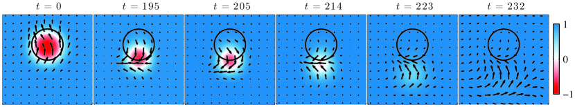
Drift instabilities were originally predicted to arise in certain regions of the available parameter space, although it appeared complex to designate which regions are stable and which are not Hoefer2010 . Later theoretical work uncovered well-defined boundaries as functions of current and field, where the droplet is either linearly stable or deterministically prone to drift. The deterministic drift instability regime develops in the region of high current and field. Furthermore, thermal fluctuations give rise to additional rare events where the droplet experiences drift. Factors that promote a stable state are a large NC, low field, moderate current, and high perpendicular anisotropy. Wills2016
The significance of temperature was further investigated, and the authors could conclude ”Consequently, we have shown that the droplet’s ”drift” instability is unavoidable in a finite-temperature device.” But they also stated that rare events can be reduced. Moore2019 The significance of the RL magnetization canting angle has not been systematically investigated, although it was included in the earliest paper Hoefer2010 . In both Ref. Wills2016 and Moore2019 the reference layer magnetization was considered to be parallel to the applied field, perpendicular to the sample plane.
Initial experimental studies only probed the high-frequency dynamics, and overlooked any signals arising from slow drift instabilities Mohseni2013a ; Macia2014 ; Mohseni2014 ; Chung2014 . Albeit drift was acknowledged, it was believed that hysteresis warrants stable droplets. This idea was challenged by experiments and micromagnetic simulations, which proved that low-frequency signals (hundreds of MHz) can arise from periodic drift instabilities even in the hysteretic regime, since the droplet is inclined to re-nucleate as long as there still is some SW precession underneath the nanocontact. Lendinez2015 .
Later low-frequency noise became identified as a characteristic of the droplet Chung2016 and a means to distinguish the soliton state in all-perpendicular STNOs Chung2018PRL ; Ahlberg2022 ; Shi2022 . However, the droplet does not experience drift in all parameter space, but there exists field and current combinations where the low-frequency power is zero, and the designation of stable/unstable regions is indeed complex Jiang2018pra ; Ahlberg2022 . Moreover, although the details of the measured noise are very reproducible for an individual device, it differs between samples Ahlberg2022 . Further experiments are needed to resolve all aspects of drift instabilities.
5.3 Automodulation and Perimeter Modes
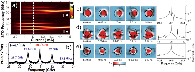
The droplet’s main frequency is sometimes accompanied by modulation sidebands. They have been observed in both early simulations Finocchio2013 and experiments. An example of the latter is found in Fig. 7(a) and the cut along the dashed white line is displayed in Fig. 7(b). Since the external drive is simply a dc current, the sidebands must arise from intrinsic automodulation. Simulations tuned to specific sets of parameters unfolded a number of scenes corresponding to GHz-signals outside the main frequency. Figure 7(c) illustrates how the droplet experiences an approximate circular (gyrotropic) motion underneath the NC. Another scenario is displayed in Fig. 7(d) where the droplet rotates at the NC edge, producing concomitant propagating spin waves. This situation gives rise to clear sidebands. Lastly, Fig. 7(e) reveals a breathing mode associated with frequencies at and of the fundamental mode. Mohseni2013a
A new perspective on the appearance of sidebands was presented in a later publication Mohseni2020prb . The droplet motion was described in terms of inertia and effective mass, giving similar conclusions as numerical studies discussing “the basin of attraction” Wills2016 ; Moore2019 . That is, the droplet experiences a restoring force when field gradients drive it out of the NC area. Both views establish that droplets in large nanocontacts and high perpendicular fields are less susceptible to drift. The simulations in Ref. Mohseni2020prb expose that inertia responding to the Oersted field force leads to additional modes evidenced by sideband signals. Mapping of the spatial profiles of the sideband frequencies unveils that the sideband mode with above the main frequency precesses clockwise, while the low-f mode precesses counterclockwise.
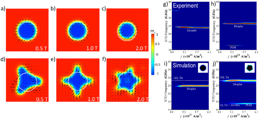
Further dynamics have been experimentally detected. For certain conditions, a single frequency emerges below the fundamental signal. This frequency is associated with perimeter excitation modes (PEMs), that are ordered perimeter distortions. Ordinary stable droplets are depicted in Fig. 8(a)–(c), and PEMs in (d)–(f). To excite these modes the magnetization of the reference layer needs to be nearly perpendicular to the sample plane. That condition fulfilled, a particular PEM will evolve when the fundamental droplet frequency is close to double that of the PEM, which signifies that the process is parametric. Fig. 8(g)–(h) and (i)–(j) represents experimental and simulation data, respectively. The data convincingly corroborate the existence of PEMs, and also show that they disappear at high currents (Fig. 8(h)). Xiao2017 Signals associated with PEMs have been measured in Ref. Mohseni2020prb as well, and possibly in Ref. Jiang2018pra . In addition, these modes are readily encountered in simulations.
5.4 Multiple Modes
Droplets in real materials with defects and disorder, cannot be described simply by a single set of material parameters and a few well-defined perturbations, such as the Oersted field and temperature. On the contrary, reproducible kinks in the magnetoresistance Chung2014 ; Macia2014 ; Lendinez2015 ; Chung2016 as well as signals deviating from a continuous function Mohseni2013a ; Mohseni2014 ; Lendinez2015 , are commonly found in experiments. These variations are most likely connected to droplet mode transitions, ultimately caused by the complex energy landscape.
Statuto et al. Statuto2019 examined devices displaying a number of separate fundamental mode frequencies, manifested in both field and current sweeps. The authors linked the low-frequency noise to the high-frequency behavior and identified distinct droplet modes. The modes are tied to particularities in the energy landscape. Moreover, droplets at low currents may be very stable with no concomitant low-frequency noise, not even during mode transitions. In contrast, noise is always present when the droplet experiences instabilities, and then the noise amplitude increases substantially when the droplet shifts from one mode to another.
Similarly, kinks in the MR usually reflect mode transitions with concomitant low-frequency noise. This has been observed for symmetric all-perpendicular STNOs Ahlberg2022 . Traces of mode transitions are clearly seen in the integrated noise map presented in Fig. 10b) in Sec. 6.4. Well-defined droplet modes have also been reported in Ref. Mohseni2014 .
6 Control and Maneuvering
6.1 Propagation and Collisions
Propagating and/or interacting droplets has thus far not been studied experimentally, but theoretical work has unveiled intriguing features which warrant attention.
Droplets can be made to propagate by a field gradient, and the propagation will be in the direction of the lower field. In the absence of damping a moving droplet is robust and keeps its size, frequency, and velocity even if it is exposed to significant perturbations Hoefer2012physD . However, damping is always present, albeit small and/or effectively tuned to zero by spin currents. The propagation of droplets in realistic settings has been studied analytically together with micromagnetic simulations. Under the action of damping, the droplet velocity accelerates while its size decreases and the frequency increases accordingly. When the frequency reaches the ferromagnetic resonance, the droplet collapses into spin waves. Nonetheless, by using a feed-back controlled alternating applied field, the droplet motion can be stabilized and the velocity kept constant. Hoefer2012
An effective field gradient can also be realized by alteration of the host material’s anisotropy. In Ref. Mohseni2020pra they model a waveguide where the material surrounding the NC has a higher anisotropy than the area next to the NC designed for droplet propagation. The droplet escapes the NC due to the gradient and propagates in an almost straight line only distorted by small wiggles around the main direction. Despite moderate damping the droplet can travel up to a micrometer until it eventually annihilates. The annihilation process results in a burst of spin waves, whose wave-vectors are set by the droplet’s initial velocity. The moving droplet can thus be used as a mobile SW source with a given emission direction. Spin Hall nano-oscillators can also host droplets, which spontaneously leave the active area and propagate for more than 1.5 m.
An often-stated attribute of solitons is that they are unaffected by collisions, keeping their original shape. However, this is only true for classical, conservative solitons and should not be assumed valid for dissipative states. Purwins2010
Collisions between two droplets can be categorized by their relative phase (of the perimeter precession) and momenta (velocities). They will experience an attractive interaction if they are in-phase, and a repulsive interaction if they are out-of-phase. For intermediate phases they are either attracted or repulsed; the two forms of interaction are separated by a critical phase difference . Four typical scenarios have been described. i) Small velocity, small phase difference: the droplets merge and form a breathing mode, see Fig. 9(a). ii) Large velocity, small phase difference: the droplets merge, unmerge and continue in opposite directions along the symmetry axis, see Fig. 9(b). iii) Any velocity, the phase difference larger than : reflection reminiscent of Bragg’s law, see Fig. 9(c). iv) Any velocity, the phase difference close to : the droplets merge, collapse into spin waves, and re-nucleates as a moving single droplet, see Fig. 9(d–g). Maiden2014
6.2 Routing
Droplet propagation can be controlled by utilizing voltage controlled magnetic anisotropy (VCMA). Micromagnetic simulations have been used to outline a routing device for magnetic droplets. The envisioned device consists of a MgO/Fe/MgO trilayer shaped into a small rectangular waveguide connected to a larger routing area. A circular gate electrode and a semiconducting nanostripe are placed on the waveguide and the routing area, respectively. First, the droplet is nucleated underneath the circular electrode by applying a nanosecond voltage pulse, which temporarily reduces the PMA. A small constant in-plane field is also used to further destabilize the OOP magnetization. The droplet is accelerated by the gradient of the demagnetization field in the waveguide and propagates toward the stripe electrode. Next, a semiconducting stripe is biased by a dc voltage giving rise to a PMA gradient perpendicular to the droplet path. The droplet turns by an angle set by the dc bias, changing the direction up to °. The maximum propagation length is m. Consequently, an input voltage can be used to route the droplet to different output MTJ gates where it can be electrically detected. Nikitchenko2022
6.3 Merging
Interactions between lateral droplet pairs can also occur if two neighboring nanocontacts host one droplet each. If they are close enough, the droplets may merge. This process is the topic of Ref. Xiao2016 . They use zero-temperature simulations of an all-perpendicular system to map out the conditions of merging. The maximum NC spacing is a function of applied field and current. It decreases with field and increases with current, reaching a plateau. The merging process is reversible, but it takes very high fields, up to 7–8 T, to re-separate the droplets. An intermediate state precedes the separation. At medium fields the merged droplet is highly unstable and takes a hollow shape, resembling a donut. Once disconnected, the droplets stay detached while the field is decreased down to T where they again merge. Thus, the process show hysteresis. A notable similarity to the interactions during collisions is that the droplets must precess in-phase to merge. The pair spontaneously synchronize if they are generated simultaneously, but if they form at different times, they may develop opposite phase making merging impossible. External manipulation of the droplet synchronization is possible by means of mutual lock-in to an oscillating microwave magnetic field. Wang2017
6.4 Freezing
Early droplet research consistently used orthogonal STNOs, since they allow for detection of the fundamental precession frequency. However, this hindered the exploration of the low field limit of the droplet phase diagram. The knowledge about this regime only relied on simulations and they suggested that the droplet should be stable in zero field and only annihilate once the current was switched off. Macia2014 Recently, Ahlberg et al. have utilized all-perpendicular devices to experimentally access the full field range of droplet existence. Ahlberg2022 They discovered that the droplet freezes at low fields into a static nanobubble, which is stabilized by domain wall pinning to magnetic inhomogeneities. Moreover, the nanobubble survives in zero current and persists for days, if not longer. Their conclusions based on in-house electrical measurements were confirmed by STXM images.
Figure 10 presents a droplet phase diagram based on measurements of the magnetoresistance and integrated low-frequency noise. The low-frequency noise emerges when the droplet moves around the nanocontact, or experiences continuing annihilation/re-nucleation. The nanobubble is static and produces no microwave signal. As seen in the figure (Fig. 10), the bubble nucleates already at currents below the droplet threshold of mA. At larger currents the droplet state preexists the bubble, and the transition generates large noise. The noise arises from erratic dynamics linked to sporadic pinning to magnetic defects. The transition droplet–bubble is fully reversible without any hysteresis, and thus there is no energy barrier between the two states. Consequently, it is possible to toggle between a dynamic and a static mode, and save the latter, which could be of interest for potential applications.
7 Miscellaneous Devices
7.1 Voltage controlled magnetic anisotropy (VCMA)
One approach to control the magnetization dynamics is to employ voltage-controlled magnetic anisotropy Wang2012 ; Shiota2012 ; Verba2014 . Simulations show that this effect provides an effective method to tune the auto-oscillation mode from droplet to propagating spin waves.
The dynamics has been mapped out as a function of electric field , where corresponds to zero effective PMA. Zheng2020 In contrast to the commonly used layout of an NC in an extended film, the simulated device had a well-defined radius of 256 nm, i.e. a nanopillar structure. This means that the SWs can be reflected at the device boundary and confinement is important.
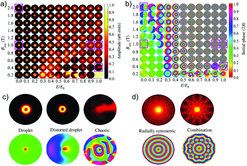
At a low electrical field, an ordinary droplet is formed, which displays the usual sub-FMR frequency. However, at the droplet frequency crosses the FMR. Further increase in leads to a droplet mode with a frequency significantly above FMR. The droplet becomes distorted, its diameter decreases, and the in-plane precession coherency is lost, but the component stays reversed. Thus, the mode can still be regarded as localized, whereas the unexpectedly high frequency must originate from an interplay between the droplet and simultaneously excited spin waves. Above the localization vanishes and the dynamics consists solely of propagating spin waves.
Figure 11 displays an exhaustive phase diagram of the dynamic state as a function of and applied field, constructed of Fourier transform images of the excited modes. Figure 11(a) show the Fourier amplitude, and Fig. 11(b) the Fourier phase. Different enlarged examples are found in Fig. 11(c) and (d). At low magnetic and electric fields, the ordinary droplet is stable. In higher magnetic fields, the main frequency crosses the FMR and a distorted droplet is present. High , i.e. low PMA, facilitates propagating spin waves, but without a strong stabilizing -field, the coherent SWs collapse into chaotic patterns.
The simulations described above did not take the Oersted field into account, which can be justified by the small magnitude of compared to the edge demagnetization field in the nanopillar geometry. A later publication included the Oersted field and discovered a new droplet-like configuration, which was denoted a spiral mode. Zheng2021 This mode appears at low currents and is attributed to a competition between , which is directed clock-wise, and the inertia of the inherent STT-driven droplet precession, which is counter-clock-wise. The spiral mode only exists for quite low and currents, while the distorted droplet emerges if the PMA is reduced. Both modes transform into an ordinary droplet at high currents.
7.2 Magnetic Tunnel Junction (MTJ)
Two desired properties of potential devices are tunability and a strong output signal. Magnetic tunnel junctions can be utilized to achieve both. MTJs are superior to spin valves and SHNOs in terms of power emission, since the magnetoresistance ratio can be orders of magnitude larger: 200% Wang2018 , or even 600% Ikeda2008 . However, the high resistance tunnelling barrier makes it impossible to use the standard NC-STNO mesa design. The current will flow through the top layers to the ground, instead of getting spin-polarized during tunneling. A common method to restrain the current flow is to use the nanopillar design, but droplets have not been experimentally observed in that type of device. Instead, careful manufacturing of devices where the current is forced to pass the tunnel layer is needed.
The magnetodynamics of sombrero-shaped MTJs with PMA-free layers was studied, but droplets were not detected Jiang2019 . This called for a revised device design, and droplets were later demonstrated in similar MTJs with a double free layer. Shi2022 The new design reduced the lateral current density () by half, thereby also reducing the Zhang-Li torque, which appears to be detrimental to droplet stability. Simulations showed that the soliton also may appear in single free layer MTJs, but only in a narrow current range. In contrast, with double free layers the available current range is wide, and local inhomogeneities promote an even wider range.
7.3 Exchange Spring Magnet
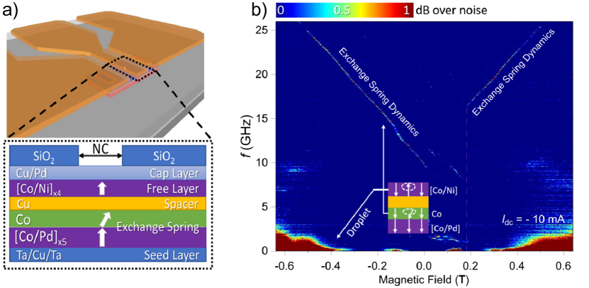
The droplet typically forms in magnetic materials with strong perpendicular magnetic anisotropy, where an in-plane or out-of-plane reference layer is used. Recently, Jiang et al. Jiang2023 attempted to generate droplets using an exchange-spring-based RL. This reference layer comprises a thick Co layer with in-plane magnetic anisotropy (IMA) and a [Co/Pd] multilayer with strong PMA. By controlling the IMA and PMA, the exchange-coupled structure enables the realization of the tilted anisotropy illustrated in Fig. 12(a). Notably, the formation and dynamic behavior of the droplets were observed in the exchange-spring layer as seen in Fig. 12(b). These exchange-spring spin-torque nano-oscillators also function as bipolar oscillators, operating under both positive and negative currents. This significantly broadens the design possibilities and functionality of the current STNO technology for energy-efficient high-frequency spintronic and neuromorphic applications.
7.4 Nanowire STNO
Physical confinement is an important aspect of all nanoscience. The impact of lateral boundaries on the magnetic droplet has been investigated in a publication by Iacocca et al. Iacocca2014 . They used micromagnetic simulations of nanowire (NW) STNOs and discovered that the droplet envelope transforms as the NW width decreases. Three modes were identified: an ordinary droplet (M1, Fig. 13(a)), a half 2D-droplet attached to one NW edge (M2, Fig. 13(b)), and a chiral quasi-1D droplet appended to both NW edges (M3, Fig. 13(c)). The frequency as a function of nanowire width is given in Fig. 13(d), where the different modes are easily distinguished. Including temperature in the simulations gave the same results, but the frequencies were slightly shifted towards the Zeeman frequency.

The half 2D-droplet behaves simply as an ordinary droplet in all essential means. The large footprint leads to a low frequency, but this can be described using the same analytical expression as for M1 (red lines in Fig. 13). Whether the droplet sticks to the upper or lower edge is a random process. The physical trigger for the mode transformation between M1 to M2 is still not fully understood.
The quasi-1D droplet exhibit a sub-Zeeman frequency, which the authors link to the topological quality of the mode. The sub-Zeeman value persists when the external field is varied, and of M3 has a slope of GHz/T. Furthermore, the quasi-1D droplet is effectively described by the same theory as conservative 1D magnetic solitons in biaxial materials, with a few quantitative exceptions. The dissipative droplet only exhibits breathing (oscillating size) in non-zero applied fields, and the breathing matches the precessional frequency, not twice the precessional frequency.
Experiments on droplets in nanowires have only been reported in brief, but the results suggest a transition to the half 2D-droplet edge mode with increasing field or current Chung2015 . A more comprehensive study is needed to confirm the findings in simulations. Nevertheless, it is important to consider the effects of physical confinement when designing spintronic droplet devices.
7.5 Spin Hall Nano-oscillator (SHNO)
The NC-STNO has dominated droplet science thus far, but there are other mechanisms to produce spin currents/torque and overcome damping. One of them is the spin Hall effect (SHE). This mechanism occurs in materials with strong spin orbit coupling, where spin dependent scattering generates a spin current transverse to the electronic current flow Song2020 . Devices relying on this effect are referred to as spin Hall nano-oscillators (SHNOs) Chen2016 . Only two layers are needed: one heavy metal with strong spin-orbit coupling, and one magnetic layer. The current flow needs to be restrained to a limited area to get substantial current densities and thereby a large spin torque. A common means to define an active area is by pattern nanoconstrictions Demidov2014apl ; Mazraati2016apl . The current, and the concomitant Oersted field and spin torque, have a much more complex distribution in SHNOs compared to STNOs.
Divinskiy et al. were the first to report on droplets in SHNOs, using the very term magnetic droplet soliton Divinskiy2017 . (It can be discussed whether earlier experimental data interpreted as the dynamical skyrmion Liu2015 , in fact corresponds to a droplet Akerman2018 .) In Ref. Divinskiy2017 they use a device with a nanoconstriction width of 100 nm, and utilize micromagnetic simulations to picture the droplet behavior. At the initial state, when the droplet just has nucleated, there is a striking resemblance with the nanowire setting. The droplet attaches to one of the edges and has a size of the order of the constriction radius. However, the complex effective field landscape comes into play at longer time scales. Due to in-plane torques, the droplet grows, covers the full active area, and displays intricate dynamics. Thus, the SHNO layout cannot be expected to host well-defined, stable droplets. There is an advantage, though. The current covers an extended area, albeit weakened outside the constriction. The simulations show that a droplet can escape the active area and propagate more than 1.5 m. Consequently, SHNOs may be a good system to experimentally study droplet propagation.
Another SHNO design uses nanocontacts to restrain the current flow, just as in STNOs. Unsurprisingly, droplets have been detected in these devices as well Chen2020pra . The magnetic layer had a crystalline easy-axis anisotropy (along ) slightly weaker than the demagnetization field, which resulted in a small in-plane anisotropy, and the external field was directed almost perpendicular to the film plane () Under these conditions a mode transition occurs at cryogenic temperatures. At small currents a bullet soliton gerhart2007prb ; slavin2005prl is formed, which transforms into the droplet soliton above a threshold current. Measurements at room temperature only reveal a single droplet mode.
7.6 Exotic spin-orbit torque
The conventional SHNOs described in the last chapter (Sec. 7.5), only produce in-plane spin-torques by symmetry. But recent studies have found materials that generates out-of-plane spin-torque components as well, such as WTe2 MacNeill2017 , Mn3GaN Nan2020 , and IrMn3 Liu2019 . Klause and Hoffman have utilized the prospect of perpendicular torques, which they call exotic spin-orbit torques, in simulations of a magnetic nanowire (NW). The benefit of this approach is that the anti-damping torque can be applied to the whole sample, without confined constrictions or nanocontacts. Yet, the sample dimensions must be small enough to allow for high current densities. They used an area of 1125250 nm2 with a magnetic layer thickness of 5 nm.
They observed nucleation of droplets and followed the time evolution of the magnetization. First, a single droplet was formed in the middle of the nanowire. The nucleation spot was determined by the dipolar fields at zero temperatures, but became random if significant thermal fluctuations were included. A couple of nanoseconds after nucleation, the droplet had grown, and two additional droplets appeared at each side of the first one. The pair shared the same phase, while the initial droplet precessed independently. The droplets expanded with time, and yet another pair formed to the sides of the existing trio. Also this pair shared a common phase. In the next steps, droplets merged and attached to the NW boundary, forming quasi-1D droplets (see Sec. 7.4). When this happened, the original coherency of the spin precession was lost, and the droplet dynamics became chaotic. New small droplets emerged continuously. The continuous formation and growth of solitons could be stopped by taking advantage of that lower currents are needed to sustain, than to nucleate a droplet. By pulsing the applied current, the number of droplets could be controlled by the length and amplitude of the pulse. Klause2022
8 Other Resemblant Solitons
8.1 AFM and FiM Drops
Alongside ferromagnetic drops, equivalent soliton solutions have also been theoretically predicted for materials with other types of magnetic ordering - antiferromagnets (AFMs) and ferrimagnets (FiMs).
Magnetic drops in AFMs can benefit from the intrinsic ultra-fast spin dynamics inherent for these materials. Contrary to ferromagnets, uniaxial quadratic anisotropy (in the form ) does not provide necessary nonlinear coupling between magnons in AFMs. It was proposed in Refs. Kosevich1990 ; baryakhtar1983dynamical to employ higher-order terms in the anisotropy energy density, i.e. , to stabilize drops. The two anisotropy constants together with the exchange field defines the characteristic frequencies of the AFM: the antiferromagnetic resonance and the maximum-opening-angle precession frequency , which usually are in a sub-THz range for common AFM materials. The frequency of the drops is predicted to lay below the AFM resonance in the range . In contrast to ferromagnets, where the magnetization is reversed in the center of a droplet, the maximum opening angle of the Néel vector precession is .
The AFM drop solution requires particular signs of the anisotropy constants , which reduces the choice of the possible materials. The required form of anisotropy is reported for hematite Morrish1995 , where both and can be additionaly tuned by doping elements, such as Ru, Rh, Al and Ga Hayashi2021 . These properties make hematite a promising candidate for realizing AFM droplets in experiments.
It has also been shown theoretically that conservative and STT-stabilized drops (i.e. the latter are droplets) can form in two-sublattice FiMs zaspel2023ferrimagnetic . It was found that the properties of a conservative FiM drop is similar to the ferromagnetic one, but with a rescaled frequency, which strongly depends on the compensation of angular momentum between the sublattices, varying from the sub-THz range in the vicinity of a compensation point to the GHz range typical for ferromagnets.
8.2 Dynamical Skyrmion
Just as droplets, dynamical skyrmions (DS) were first investigated for idealized models of magnets without dissipation Kovalev1979 ; Voronov1983 . They are named after their static counterpart, the magnetic skyrmion. The common attribute is a non-zero topological charge777This value is also known as a topological index, or skyrmion number., which is given by Moutafis2009 ; Braun20121 . The topological character implicates that the state is exceedingly stable against perturbations, and this feature has motivated an enormous research interest in magnetic skyrmions Nagaosa2013 ; Fert2017 ; Everschor-Sitte2018 .
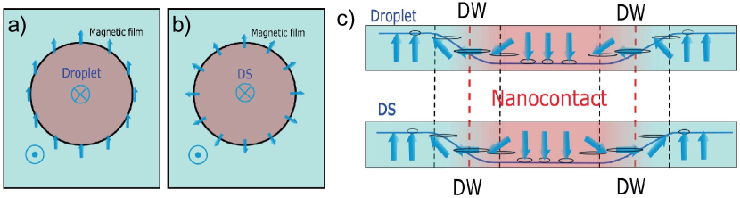
Systems that host dissipative droplets, can also host dynamical skyrmions. There is a considerable resemblance between the two types of solitons, but the spin texture is different, giving for droplets and for DS. Figure 14 displays schematics of the magnetic configurations. The perimeter spins of both solitons undergo precession, but while the droplet spins always keep the same phase, the dynamical skyrmion displays more intricate dynamics. The DS spins continuously alternate between all spins pointing out, clockwise alignment, all spins pointing in, and counterclockwise alignment. The dynamical soliton also exhibits breathing, i.e. the size expands and contracts. Liu2015
Two mechanisms can break the trivial topology of the droplet and trigger the skyrmion symmetry: i) the current-induced Oersted field Zhou2015 ; Statuto2018 ; Zaspel2019 , and ii) the asymmetric Dzyaloshinskii–Moriya interaction (DMI) Chen2016dmi ; Song2016 . Short rise times of the applied current also favor DS formation. Statuto2018 It is important to note that DMI is not necessary for DS formation, but in simulations this asymmetric interaction is needed in order to stabilize the soliton in zero current Zhou2015 ; Carpentieri2015 ; Chen2016dmi ; Song2016 . However, as described in Sec. 6.4, droplets freeze into static bubbles when the applied field is reduced, and they prevail when the current is switched off, pinned to magnetic inhomogeneities. Potentially, DS exhibits a similar transformation, enabling nucleation of individual nanoscale skyrmions in DMI-free materials.
Thus far, dynamical skyrmions have only been studied by simulations. Experimental observation has been claimed Liu2015 , but that conclusion relied on the support of simulations. Consequently, unambiguous evidence is still lacking for the existence of real DS. Experimental evidence is challenging due to the close resemblance between DS and droplets. The nucleation process is similar and only vanishingly small deviations in frequency are expected. The dynamical skyrmion differs from the droplet by being more persisting to low sustaining currents, less prone to drift and by experiencing breathing at the precession frequency. Zhou2015 ; Statuto2018 Those subtle distinctions are too weak to verify DS observation beyond a reasonable doubt.
Direct imaging of the magnetic texture is a conceivable path to distinguish the two solitons, but the necessary length scales make it a difficult task. Nevertheless, there is an experimentally accessible method to distinguish dynamical skyrmions, which was presented already in the first publication on DS Zhou2015 . The topological soliton can injection lock to an external microwave signal via the Oersted field, while droplets cannot. This test should be straightforward and will reveal the existence of dynamical skyrmions outside the mathematical regime covered by simulations.
8.3 More Examples
Dynamical skyrmions (DS) may also be called topological droplets Carpentieri2015 , a term which highlights the topological distinction between DS and ordinary droplets. Yet again, topology is an important quality and the use of distinctive terms benefits understanding and clear communication. Correspondingly, when any new feature of the droplet is observed, it is good to reflect on whether the discovered characteristic is inherent to “an ordinary droplet”, or if the modified state warrants a specific name. Naming of different modes usually occurs in papers presenting results of simulations, since magnetic states are easily distinguished in that kind of data. The outcome of experiments is harder to identify with a specific state, although distinct signs of mode transitions have been detected Statuto2019 ; Ahlberg2022 . Based on simulations, a number of droplet states have been identified.
Unique modes appear when the standard parameters are tweaked, e.g. reducing the spatial dimensions into a nanowire leads to the formation of quasi-1D droplets Iacocca2014 , and decreasing out-of-plane anisotropy results in spiral modes and distorted droplets Zheng2021 ; Zheng2020 . Investigations of the effect of Dzyaloshinskii–Moriya interaction lead to the classification of dynamical skyrmions Zhou2015 , instanton droplets Carpentieri2015 , singular droplets and pseudo-normal droplets Chen2016 ; Song2016 , and cigar-shaped droplets Song2016 . The term instanton droplet refers to a mode that alternates between an ordinary zero-topology droplet and a topological dynamical skyrmion. In-coherent spin waves are emitted in the process. Singular droplets are asymmetric modes appearing at low currents, “named for the character of topological charge” (the meaning of that description is not elaborated in the original paper). The core of the pseudo-normal droplet encircles the center of the nanocontact, and perhaps this minor deviation from normal is overstressed by giving the mode a prefix. Cigar-shaped droplets carry a topological charge of , and exhibit a peculiar shape described by its name.
9 Summary and Outlook
In summary, nowadays the magnetic droplet is a mature research object, and many of its mysteries have been resolved. Both experiments and simulations have provided pieces of vital knowledge needed to one day put the phenomena to use. However, simulations outnumber experiments by far, and although the interpretation of experiments needs computational aid, the validity of simulations may often be questioned. Good practice is to always include the Oe-field, which is a fundamental perturbation in a real system. Another disputed parameter is temperature. Experiments are rarely made at cryogenic temperatures Macia2014 ; Lendinez2017 ; Statuto2019 ; Chen2020pra . In contrast, most simulations ignore temperature effects with few exceptions Iacocca2014 ; Puliafito2014 ; Zhou2015 ; Statuto2018 . Fortunately, any quantitative modifications of the droplet state by temperature have not been observed. The effect of thermal fluctuations seems to be limited to details, such as the droplet stability, the nucleation current, and the coherence of the dynamics—all important details in designing reliable devices, but maybe of less academic interest. Generally, simulations may be tweaked in numerous ways, but one needs experimental support to sort out what is important.
For years, the promise of using droplets in applications has been used as a motivation for further studies. Mentioned applications include magnetic random access memory (MRAM) Okamoto2015 , magnonics Barman_2021 , neuromorphic computing Romera2018 ; Zahedinejad2020 , radio-frequency electronics Choi2014 ; Sharma2021 , and Ising machines Albertsson2021 . They all remain potential technologies, but recently a new flavor has emerged. Ferri- and antiferromagnetic materials are growing fields within spintronics and magnonics Kim2017 ; Caretta2018 ; Jungwirth2016 ; Wadley2016 ; Baltz2018 , and we expect that droplets soon will be explored in those materials. Just as drops exist (mathematically) in both FMs and AFMs, droplets with Neél order will take shape in proper devices. This is an exciting next step in droplet research. Besides, the realization of propagating droplets is an appealing route towards both a more complete experimental picture as well as applications.
Acknowledgements
We thank B. Ivanov for valuable discussions. This work was partially supported by the Swedish Research Council (VR Grants 2016-05980 and 2017-06711) and the Knut and Alice Wallenberg Foundation.
References
- (1) Purwins, H.-G., Bödeker, H. U. & Amiranashvili, S. Dissipative solitons. Adv. Phys. 59, 485–701 (2010). DOI https://doi.org/10.1080/00018732.2010.498228.
- (2) Ivanov, B. A. & Stephanovich, V. A. Two-dimensional soliton dynamics in ferromagnets. Phys. Lett. A 141, 89–94 (1989). DOI https://doi.org/10.1016/0375-9601(89)90453-2.
- (3) Kosevich, A. M., Ivanov, B. A. & Kovalev, A. S. Dynamical and topological solitons in a ferromagnet. Physica D 3, 363–373 (1981). DOI https://doi.org/10.1016/0167-2789(81)90140-8.
- (4) Kosevich, A. M., Ivanov, B. A. & Kovalev, A. S. Magnetic solitons. Phys. Rep. 194, 117 (1990). DOI https://doi.org/10.1016/0370-1573(90)90130-T.
- (5) Bespyatykh, Y. I., Dikshtein, I. E. & Nikitov, S. A. 3D surface precession solitons (surface magnetic drops) in uniaxial magnets. Phys. Lett. A 184, 198–203 (1994). DOI https://doi.org/10.1016/0375-9601(94)90777-3.
- (6) Ivanov, B. A. & Kosevich, A. M. Bound states of large number of magnons in a three-dimensional ferromagnet (magnons drops). JETP Lett. 24, 495 (1976).
- (7) Ivanov, B. A. & Kosevich, A. M. Bound states of a large number of magnons in a ferromagnet with a single-ion anisotropy. Zh. Eksp. Teor. Fiz. 72, 2000 (1977). (English Translation in Sov. Phys. JETP 45, 1050 (1977).).
- (8) Hoefer, M. A., Silva, T. J. & Keller, M. W. Theory for a dissipative droplet soliton excited by a spin torque nanocontact. Phys. Rev. B 82, 054432 (2010). DOI https://doi.org/10.1103/PhysRevB.82.054432.
- (9) Mohseni, S. M. et al. Spin Torque-Generated Magnetic Droplet Solitons. Science 339, 1295 (2013). DOI https://doi.org/10.1126/science.1230155.
- (10) Sulymenko, O. R., Prokopenko, O. V., Tyberkevych, V. S., Slavin, A. N. & Serga, A. A. Bullets and droplets: Two-dimensional spin-wave solitons in modern magnonics. Low Temp. Phys. 44, 602–617 (2018). DOI https://doi.org/10.1063/1.5041426.
- (11) Macià, F. & Kent, A. D. Magnetic droplet solitons. J. Appl. Phys. 128 (2020). DOI https://doi.org/10.1063/5.0018251.
- (12) Chung, S. et al. Magnetic droplet solitons in orthogonal spin valves. Low Temp. Phys. 41, 833–837 (2015). DOI https://doi.org/10.1063/1.4932358.
- (13) Åkerman, J. Spin Transfer Torque Driven Magnetodynamical Solitons, 335–356 (Springer International Publishing, 2018). URL https://doi.org/10.1007/978-3-319-97334-0_11.
- (14) Macià, F., Backes, D. & Kent, A. D. Stable Magnetic Droplet Solitons in Spin Transfer Nanocontacts. Nat. Nanotechnol. 9, 992 (2014). DOI https://doi.org/10.1038/nnano.2014.255.
- (15) Bonetti, S. et al. Microwave soft x-ray microscopy for nanoscale magnetization dynamics in the 5–10 ghz frequency range. Rev. Sci. Instrum. 86 (2015). DOI https://doi.org/10.1063/1.4930007.
- (16) Macià, F. et al. Perpendicular magnetic anisotropy in ultrathin CoNi multilayer films studied with ferromagnetic resonance and magnetic X-ray microspectroscopy. J. Magn. Magn. Mater. 324, 3629 (2012). DOI https://doi.org/10.1016/j.jmmm.2012.03.063.
- (17) Backes, D. et al. Direct observation of a localized magnetic soliton in a spin-transfer nanocontact. Phys. Rev. Lett. 115, 127205 (2015). DOI https://doi.org/10.1103/PhysRevLett.115.127205.
- (18) Burgos-Parra, E. et al. Investigation of magnetic droplet solitons using x-ray holography with extended references. Sci. Rep. 8, 11533 (2018). DOI https://doi.org/10.1038/s41598-018-29856-y.
- (19) Chung, S. et al. Direct Observation of Zhang-Li Torque Expansion of Magnetic Droplet Solitons. Phys. Rev. Lett. 120, 217204 (2018). DOI https://doi.org/10.1103/PhysRevLett.120.217204.
- (20) Guizar-Sicairos, M. & Fienup, J. R. Holography with extended reference by autocorrelation linear differential operation. Opt. Express 15, 17592 (2007). DOI https://doi.org/10.1364/OE.15.017592.
- (21) Guizar-Sicairos, M. & Fienup, J. R. Direct image reconstruction from a fourier intensity pattern using HERALDO. Opt. Lett. 33, 2668–2670 (2008). DOI https://doi.org/10.1364/OL.33.002668.
- (22) Thole, B. T., Carra, P., Sette, F. & van der Laan, G. X-ray circular dichroism as a probe of orbital magnetization. Phys. Rev. Lett. 68, 1943–1946 (1992). DOI https://doi.org/10.1103/PhysRevLett.68.1943.
- (23) Chen, C. T. et al. Experimental Confirmation of the X-Ray Magnetic Circular Dichroism Sum Rules for Iron and Cobalt. Phys. Rev. Lett. 75, 152 (1995). DOI https://doi.org/10.1103/PhysRevLett.75.152.
- (24) Albert, J., Macià, F. & Hernàndez, J. M. Effect of the Zhang-Li torque on spin-torque nano-oscillators. Phys. Rev. B 102, 184421 (2020). DOI https://doi.org/10.1103/PhysRevB.102.184421.
- (25) Chung, S. et al. Magnetic droplet nucleation boundary in orthogonal spin-torque nano-oscillators. Nat. Commun. 7, 11209 (2016). DOI https://doi.org/10.1038/ncomms11209.
- (26) Slonczewski, J. Excitation of spin waves by an electric current. J. Magn. Magn. Mater. 195, 261–268 (1999). DOI https://doi.org/10.1016/S0304-8853(99)00043-8.
- (27) Slonczewski, J. C. Currents and torques in metallic magnetic multilayers. J. Magn. Magn. Mater. 247, 324 (2002). DOI https://doi.org/10.1016/S0304-8853(02)00291-3.
- (28) Jiang, S. et al. Impact of the Oersted field on droplet nucleation boundaries. IEEE Magn. Lett 9, 1–4 (2018). DOI https://doi.org/10.1109/LMAG.2018.2850007.
- (29) Jiang, S. et al. Using Magnetic Droplet Nucleation to Determine the Spin Torque Efficiency and Asymmetry in Cox(Ni,Fe)1-x Thin Films. Phys. Rev. Appl. 10, 054014 (2018). DOI https://doi.org/10.1103/PhysRevApplied.10.054014.
- (30) Lendínez, S. et al. Effect of temperature on magnetic solitons induced by spin-transfer torque. Phys. Rev. Applied 7, 054027 (2017). DOI https://doi.org/10.1103/PhysRevApplied.7.054027.
- (31) Mohseni, M. & Mohseni, S. M. Designing magnetic droplet soliton nucleation employing spin polarizer. Nanotechnology 29, 155402 (2018). DOI https://doi.org/10.1088/1361-6528/aaac11.
- (32) Mohseni, M. et al. Magnetic droplet soliton nucleation in oblique fields. Phys. Rev. B 97, 184402 (2018). DOI https://doi.org/10.1103/PhysRevB.97.184402.
- (33) Lendínez, S., Statuto, N., Backes, D., Kent, A. D. & Macià, F. Observation of droplet soliton drift resonances in a spin-transfer-torque nanocontact to a ferromagnetic thin film. Phys. Rev. B 92, 174426 (2015). DOI https://doi.org/10.1103/PhysRevB.92.174426.
- (34) Hang, J., Hahn, C., Statuto, N., Macià, F. & Kent, A. D. Generation and annihilation time of magnetic droplet solitons. Sci. Rep. 8, 6847 (2018). DOI https://doi.org/10.1038/s41598-018-25134-z.
- (35) Xiao, D. et al. Parametric autoexcitation of magnetic droplet soliton perimeter modes. Phys. Rev. B 95, 024106 (2017). DOI https://doi.org/10.1103/PhysRevB.95.024106.
- (36) Bookman, L. D. & Hoefer, M. A. Analytical theory of modulated magnetic solitons. Phys. Rev. B 88, 184401 (2013). DOI https://doi.org/10.1103/PhysRevB.88.184401.
- (37) Yazdi, H. F., Ghasemi, G., Mohseni, M. & Mohseni, M. Tuning the dynamics of magnetic droplet solitons using dipolar interactions. Phys. Rev. B 103, 024441 (2021). DOI https://doi.org/10.1103/PhysRevB.103.024441.
- (38) Mohseni, S. M. et al. Magnetic droplet solitons in orthogonal nano-contact spin torque oscillators. Physica B 435, 84–87 (2014). DOI https://doi.org/10.1016/j.physb.2013.10.023.
- (39) Mohseni, M. et al. Chiral excitations of magnetic droplet solitons driven by their own inertia. Phys. Rev. B 101, 020417 (2020). DOI https://doi.org/10.1103/PhysRevB.101.020417.
- (40) Statuto, N., Hahn, C., Hernàndez, J. M., Kent, A. D. & Macià, F. Multiple magnetic droplet soliton modes. Phys. Rev. B 99, 174436 (2019). DOI https://doi.org/10.1103/PhysRevB.99.174436.
- (41) Wills, P., Iacocca, E. & Hoefer, M. A. Deterministic drift instability and stochastic thermal perturbations of magnetic dissipative droplet solitons. Phys. Rev. B 93, 144408 (2016). DOI https://doi.org/10.1103/PhysRevB.93.144408.
- (42) Moore, R. O. & Hoefer, M. A. Stochastic ejection of nanocontact droplet solitons via drift instability. Phys. Rev. B 100, 014402 (2019). DOI https://doi.org/10.1103/PhysRevB.100.014402.
- (43) Chung, S. et al. Spin transfer torque generated magnetic droplet solitons. J. Appl. Phys. 115, 172612 (2014). DOI https://doi.org/10.1063/1.4870696.
- (44) Ahlberg, M. et al. Freezing and thawing magnetic droplet solitons. Nat. Commun. 13, 2462 (2022). DOI https://doi.org/10.1038/s41467-022-30055-7.
- (45) Shi, K. et al. Observation of magnetic droplets in magnetic tunnel junctions. Sci. China: Phys. Mech. Astron. 65, 227511 (2022). DOI https://doi.org/10.1007/s11433-021-1794-4.
- (46) Finocchio, G. et al. Nanoscale spintronic oscillators based on the excitation of confined soliton modes. J. Appl. Phys. 114, 163908 (2013). DOI https://doi.org/10.1063/1.4827384.
- (47) Hoefer, M. A. & Sommacal, M. Propagating two-dimensional magnetic droplets. Physica D 241, 890–901 (2012). DOI https://doi.org/10.1016/j.physd.2012.02.003.
- (48) Hoefer, M. A., Sommacal, M. & Silva, T. J. Propagation and control of nanoscale magnetic-droplet solitons. Phys. Rev. B 85, 214433 (2012). DOI https://doi.org/10.1103/PhysRevB.85.214433.
- (49) Mohseni, M. et al. Propagating magnetic droplet solitons as moveable nanoscale spin-wave sources with tunable direction of emission. Phys. Rev. Appl. 13, 024040 (2020). DOI https://doi.org/10.1103/PhysRevApplied.13.024040.
- (50) Maiden, M. D., Bookman, L. D. & Hoefer, M. A. Attraction, merger, reflection, and annihilation in magnetic droplet soliton scattering. Phys. Rev. B 89, 180409 (2014). DOI https://doi.org/10.1103/PhysRevB.89.180409.
- (51) Nikitchenko, A. I. & Pertsev, N. A. Generation and routing of nanoscale droplet solitons without compensation of magnetic damping. Phys. Rev. Mater. 6, L101401 (2022). DOI https://doi.org/10.1103/PhysRevMaterials.6.L101401.
- (52) Xiao, D. et al. Merging droplets in double nanocontact spin torque oscillators. Phys. Rev. B 93, 094431 (2016). DOI https://doi.org/10.1103/PhysRevB.93.094431.
- (53) Wang, C., Xiao, D., Zhou, Y., Åkerman, J. & Liu, Y. Phase-locking of multiple magnetic droplets by a microwave magnetic field. AIP Adv. 7, 056019 (2017). DOI https://doi.org/10.1063/1.4975660.
- (54) Wang, W.-G., Li, M., Hageman, S. & Chien, C. L. Electric-field-assisted switching in magnetic tunnel junctions. Nat. Mater. 11, 64–68 (2012). DOI https://doi.org/10.1038/nmat3171.
- (55) Shiota, Y. et al. Induction of coherent magnetization switching in a few atomic layers of FeCo using voltage pulses. Nat. Mater. 11, 39–43 (2012). DOI https://doi.org/10.1038/nmat3172.
- (56) Verba, R., Tiberkevich, V., Krivorotov, I. & Slavin, A. Parametric excitation of spin waves by voltage-controlled magnetic anisotropy. Phys. Rev. Appl. 1, 044006 (2014). DOI https://doi.org/10.1103/PhysRevApplied.1.044006.
- (57) Zheng, C. et al. Tuning Magnetic Droplets in Nanocontact Spin-Torque Oscillators Using Electric Fields. Phys. Rev. Appl. 14, 054001 (2020). DOI https://doi.org/10.1103/PhysRevApplied.14.054001.
- (58) Zheng, C., Zhou, S., Chen, X. & Liu, Y. Effect of Oersted field on the localized droplet mode and propagating spin waves mode excited in spin-torque nano-oscillator. J. Magn. Magn. Mater. 539, 168379 (2021). DOI https://doi.org/10.1016/j.jmmm.2021.168379.
- (59) Wang, M. et al. Current-induced magnetization switching in atom-thick tungsten engineered perpendicular magnetic tunnel junctions with large tunnel magnetoresistance. Nat. Comm. 9, 671 (2018). DOI https://doi.org/10.1038/s41467-018-03140-z.
- (60) Ikeda, S. et al. Tunnel magnetoresistance of 604% at 300K by suppression of Ta diffusion in CoFeB/ MgO/ CoFeB pseudo-spin-valves annealed at high temperature. App. Phys. Lett. 93 (2008). DOI https://doi.org/10.1063/1.2976435.
- (61) Jiang, S. et al. Magnetodynamics in orthogonal nanocontact spin-torque nano-oscillators based on magnetic tunnel junctions. Appl. Phys. Lett. 115, 152402 (2019). DOI https://doi.org/10.1063/1.5121356.
- (62) Jiang, S. et al. Field-free high-frequency exchange-spring spin-torque nano-oscillators. Nano Lett. 23, 1159–1166 (2023). DOI https://doi.org/10.1021/acs.nanolett.2c03613.
- (63) Iacocca, E. et al. Confined dissipative droplet solitons in spin-valve nanowires with perpendicular magnetic anisotropy. Phys. Rev. Lett. 112, 047201 (2014). DOI https://doi.org/10.1103/PhysRevLett.112.047201.
- (64) Song, C. et al. Spin-orbit torques: Materials, mechanisms, performances, and potential applications. Prog. Mater Sci. 116, 100761 (2020). DOI https://doi.org/10.1016/j.pmatsci.2020.100761.
- (65) Chen, T. et al. Spin-Torque and Spin-Hall Nano-Oscillators. Proc. IEEE 104, 1919 (2016). DOI https://doi.org/10.1109/JPROC.2016.2554518.
- (66) Demidov, V., Urazhdin, S., Zholud, A., Sadovnikov, A. & Demokritov, S. Nanoconstriction-based spin-Hall nano-oscillator. Appl. Phys. Lett. 105 (2014). DOI https://doi.org/10.1063/1.4901027.
- (67) Mazraati, H. et al. Low operational current spin Hall nano-oscillators based on NiFe/W bilayers. Appl. Phys. Lett. 109 (2016). DOI https://doi.org/10.1063/1.4971828.
- (68) Divinskiy, B. et al. Magnetic droplet solitons generated by pure spin currents. Phys. Rev. B 96, 224419 (2017). DOI https://doi.org/10.1103/PhysRevB.96.224419.
- (69) Liu, R. H., Lim, W. L. & Urazhdin, S. Dynamical skyrmion state in a spin current nano-oscillator with perpendicular magnetic anisotropy. Phys. Rev. Lett. 114, 137201 (2015). DOI https://doi.org/10.1103/PhysRevLett.114.137201.
- (70) Chen, L., Urazhdin, S., Zhou, K., Du, Y. W. & Liu, R. H. Magnetic droplet mode in a vertical nanocontact-based spin Hall nano-oscillator at oblique fields. Phys. Rev. Appl. 13, 024034 (2020). DOI https://doi.org/10.1103/PhysRevApplied.13.024034.
- (71) Gerhart, G., Bankowski, E., Melkov, G. A., Tiberkevich, V. S. & Slavin, A. N. Angular dependence of the microwave-generation threshold in a nanoscale spin-torque oscillator. Phys. Rev. B 76, 024437 (2007). DOI https://doi.org/10.1103/PhysRevB.76.024437.
- (72) Slavin, A. & Tiberkevich, V. Spin Wave Mode Excited by Spin-Polarized Current in a Magnetic Nanocontact is a Standing Self-Localized Wave Bullet. Phys. Rev. Lett. 95, 237201 (2005). DOI https://doi.org/10.1103/PhysRevLett.95.237201.
- (73) MacNeill, D. et al. Control of spin-orbit torques through crystal symmetry in WTe2/ferromagnet bilayers. Nat. Phys. 13, 300 (2017). DOI https://doi.org/10.1038/nphys3933.
- (74) Nan, T. et al. Controlling spin current polarization through non-collinear antiferromagnetism. Nat. Commun. 11, 4671 (2020). DOI https://doi.org/10.1038/s41467-020-17999-4.
- (75) Liu, Y. et al. Current-induced Out-of-plane Spin Accumulation on the (001) Surface of the IrMn3 Antiferromagnet. Phys. Rev. Appl. 12 (2019). DOI https://doi.org/10.1103/PhysRevApplied.12.064046.
- (76) Klause, R. & Hoffmann, A. Multiple magnetic droplet solitons from exotic spin–orbit torques. Appl. Phys. Lett. 120, 242407 (2022). DOI https://doi.org/10.1063/5.0099491.
- (77) Bar’yakhtar, I. V. & Ivanov, B. A. Dynamical solitons in uniaxial antiferromagnet. Zh. Eksp. Teor. Fiz. 85, 328–340 (1983). (English Translation in Sov. Phys. JETP 58, 190 (1983).).
- (78) Morrish, A. H. Canted Antiferromagnetism: Hematite (World Scientific, 1995). URL https://www.worldscientific.com/worldscibooks/10.1142/2518.
- (79) Hayashi, K. et al. Control of antiferromagnetic resonance and the Morin temperature in cation doped -Fe2-xMxO3 (M = Al, Ru, Rh, and In). Appl. Phys. Lett. 119, 32408 (2021). DOI https://doi.org/10.1063/5.0053586.
- (80) Zaspel, C. E., Galkina, E. G. & Ivanov, B. A. Ferrimagnetic magnon drop solitons close to the angular momentum compensation point. Phys. Rev. B 108, 064403 (2023). DOI https://doi.org/10.1103/PhysRevB.108.064403.
- (81) Kovalev, A. S., Kosevich, A. M. & Maslov, K. V. Magnetic vortex-topological soliton in a ferromagnet with an easy-axis anisotropy. JETP Lett. 30, 296 (1979).
- (82) Voronov, V. P., Ivanov, B. A. & Kosevich, A. M. Two-dimensional dynamic topological solitons in ferromagnets. Zh. Eksp. Teor. Fiz. 84, 2235 (1983). (English Translation in Sov. Phys. JETP 57, 1303 (1983).).
- (83) Moutafis, C., Komineas, S. & Bland, J. A. C. Dynamics and switching processes for magnetic bubbles in nanoelements. Phys. Rev. B 79, 224429 (2009). DOI https://doi.org/10.1103/PhysRevB.79.224429.
- (84) Braun, H.-B. Topological effects in nanomagnetism: From superparamagnetism to chiral quantum solitons. Adv. Phys. 61, 1 (2012). DOI https://doi.org/10.1080/00018732.2012.663070.
- (85) Nagaosa, N. & Tokura, Y. Topological properties and dynamics of magnetic skyrmions. Nat. Nanotechnol. 8, 899 (2013). DOI https://doi.org/10.1038/nnano.2013.243.
- (86) Fert, A., Reyren, N. & Cros, V. Magnetic skyrmions: Advances in physics and potential applications. Nat. Rev. Mater. 2, 17031 (2017). DOI https://doi.org/10.1038/natrevmats.2017.31.
- (87) Everschor-Sitte, K., Masell, J., Reeve, R. M. & Kläui, M. Perspective: Magnetic skyrmions - overview of recent progress in an active research field. J. Appl. Phys. 124, 240901 (2018). DOI https://doi.org/10.1063/1.5048972.
- (88) Statuto, N., Hernàndez, J. M., Kent, A. D. & Macià, F. Generation and stability of dynamical skyrmions and droplet solitons. Nanotechnology 29, 325302 (2018). DOI https://doi.org/10.1088/1361-6528/aac411.
- (89) Zhou, Y. et al. Dynamically stabilized magnetic skyrmions. Nat. Commun. 6, 8193 (2015). DOI https://doi.org/10.1038/ncomms9193.
- (90) Zaspel, C. E., Wysin, G. M. & Ivanov, B. A. Magnetic Chiral Solitons Stabilized by Oersted Field at a Thin-Film Nanocontact with Electric Current. Ukr. J. Phys. 64, 933–933 (2019). DOI https://doi.org/10.15407/ujpe64.10.933.
- (91) Chen, S. et al. Dynamic response for Dzyaloshinskii–Moriya interaction on bubble-like magnetic solitons driven by spin-polarized current. J. Phys. D: Appl. Phys. 49, 195004 (2016). DOI https://doi.org/10.1088/0022-3727/49/19/195004.
- (92) Song, C. et al. Effect of perpendicular magnetic field on bubble-like magnetic solitons driven by spin-polarized current with Dzyaloshinskii–Moriya interaction. J. Appl. Phys. 120, 183901 (2016). DOI https://doi.org/10.1063/1.4967798.
- (93) Carpentieri, M., Tomasello, R., Zivieri, R. & Finocchio, G. Topological, non-topological and instanton droplets driven by spin-transfer torque in materials with perpendicular magnetic anisotropy and Dzyaloshinskii–Moriya interaction. Sci. Rep. 5, 16184 (2015). DOI https://doi.org/10.1038/srep16184.
- (94) Puliafito, V. et al. Micromagnetic analysis of dynamical bubble-like solitons based on the time domain evolution of the topological density. J. Appl. Phys. 115, 17D139 (2014). DOI https://doi.org/10.1063/1.4867747.
- (95) Okamoto, S., Kikuchi, N., Furuta, M., Kitakami, O. & Shimatsu, T. Microwave assisted magnetic recording technologies and related physics. J. Phys. D: Appl. Phys. 48, 353001 (2015). DOI https://doi.org/10.1088/0022-3727/48/35/353001.
- (96) Barman, A. et al. The 2021 magnonics roadmap. J. Phys.: Condens. Matter 33, 413001 (2021). DOI https://doi.org/10.1088/1361-648x/abec1a.
- (97) Romera, M. et al. Vowel recognition with four coupled spin-torque nano-oscillators. Nature 563, 230 (2018). DOI https://doi.org/10.1038/s41586-018-0632-y.
- (98) Zahedinejad, M. et al. Two-dimensional mutually synchronized spin Hall nano-oscillator arrays for neuromorphic computing. Nat. Nanotechnol. 15, 47 (2020). DOI https://doi.org/10.1038/s41565-019-0593-9.
- (99) Choi, H. S. et al. Spin nano-oscillator-based wireless communication. Sci. Rep. 4, 5486 (2014). DOI https://doi.org/10.1038/srep05486.
- (100) Sharma, R. et al. Electrically connected spin-torque oscillators array for 2.4 GHz WiFi band transmission and energy harvesting. Nat. Commun. 12, 2924 (2021). DOI https://doi.org/10.1038/s41467-021-23181-1.
- (101) Albertsson, D. I. et al. Ultrafast Ising Machines using spin torque nano-oscillators. Appl. Phys. Lett. 118, 112404 (2021). DOI https://doi.org/10.1063/5.0041575.
- (102) Kim, K.-J. et al. Fast domain wall motion in the vicinity of the angular momentum compensation temperature of ferrimagnets. Nat. Mater. 16, 1187 (2017). DOI https://doi.org/10.1038/nmat4990.
- (103) Caretta, L. et al. Fast current-driven domain walls and small skyrmions in a compensated ferrimagnet. Nat. Nanotechnol. 13, 1154 (2018). DOI https://doi.org/10.1038/s41565-018-0255-3.
- (104) Jungwirth, T., Marti, X., Wadley, P. & Wunderlich, J. Antiferromagnetic spintronics. Nat. Nanotechnol. 11, 231 (2016). DOI https://doi.org/10.1038/nnano.2016.18.
- (105) Wadley, P. et al. Electrical switching of an antiferromagnet. Science 351, 587 (2016). DOI https://doi.org/10.1126/science.aab1031.
- (106) Baltz, V. et al. Antiferromagnetic spintronics. Rev. Mod. Phys. 90, 015005 (2018). DOI https://doi.org/10.1103/RevModPhys.90.015005.