Nonreciprocal ballistic transport in asymmetric bands
Abstract
Nonreciprocal transport in uniform systems has attracted great research interest recently and the existing theories mainly focus on the diffusive regime. In this study, we uncover a novel scenario for nonreciprocal charge transport in the ballistic regime enabled by asymmetric band structures of the system. The asymmetry of the bands induces unequal Coulomb potentials within the system as the bias voltage imposed by the electrodes inverts its sign. As a result, the bands undergo different energy shifts as the current flows in opposite directions, giving rise to the nonreciprocity. Utilizing the gauge-invariant nonlinear transport theory, we show that the nonreciprocal transport predominantly originates from the second-order conductance, which violates the Onsager reciprocal relation but fulfills a generalized reciprocal relation similar to that of unidirectional magnetoresistance. The ballistic nonreciprocal transport phenomena differ from the diffusive ones by considering the internal asymmetric Coulomb potential, a factor not accounted for in diffusive cases but undeniably crucial in ballistic scenarios. Our work opens a avenue for implementing nonreciprocal transport in the ballistic regime and provides an alternative perspective for further experimental explorations for nonreciprocal transport.
I Introduction
Reciprocity in charge transport reflects a symmetrical relationship between current and voltage, where the magnitude of current stays constant when the voltage has an opposite sign but the same value Tokura and Nagaosa (2018); Ideue and Iwasa (2021). Violations of reciprocity underpin the functionality of key electronic devices like diodes and photodetectors Fruchart et al. (2021); Akamatsu et al. (2021). Although nonreciprocal transport is commonly encountered at systems involving interfaces, such as the celebrated p-n junction, its implementation in uniform bulk materials has occurred more recently, driven by entirely different scenarios. A novel type of nonreciprocal transport, termed electric magnetochiral anisotropy (EMCA), which exhibits unidirectional magnetoresistance (UMR), was first proposed in Ref. Rikken et al., 2001. Inspired by this discovery, extensive exploration has been conducted to identify material candidates that exhibit nonreciprocal transport. Significant findings encompass chiral nanosystems Rikken et al. (2001); Krstić et al. (2002), polar semiconductors Ideue et al. (2017); Itahashi et al. (2020); Li et al. (2021), bilayer heterojunctions Avci et al. (2015); Yasuda et al. (2019); Choe et al. (2019); Shim et al. (2022); Ye et al. (2022), and topological systems Yasuda et al. (2020); Zhang et al. (2022).
On the theoretical side, a variety of mechanisms have been put forward to explain nonreciprocal transport in systems with translational symmetry. Typical scenarios include asymmetric band structures Tokura and Nagaosa (2018); Ideue et al. (2017), asymmetric inelastic scattering by spin clusters Ishizuka and Nagaosa (2020) and magnons Yasuda et al. (2016), quantum metric Kaplan et al. (2022); Wang et al. (2023), and non-Hermitian skin effect Geng et al. (2023); Shao et al. (2023). In these studies, various theoretical approaches have been employed, such as semiclassical transport equations Zhang and Vignale (2016); Ideue et al. (2017); Sterk et al. (2019); Kaplan et al. (2022) and quantum kinetic theory Freimuth et al. (2021), both of which consider the nonlinear effects of an external electric field. Here, we mainly focus on the nonreciprocal transport in the systems with asymmetric bands. The existing mechanism for this case mainly concentrates on the diffusive limitIdeue et al. (2017), and a direct extension to the ballistic limit is not feasible under the same theoretical framework. Therefore, it remains an open question that whether nonreciprocal transport can be achieved in the ballistic regime.

In this work, we give an affirmative answer to this question by showing that nonreciprocal ballistic transport can be implemented in systems featuring asymmetric band structures with the setup depicted in Fig. 1. In this scenario, the asymmetry of the bands induces unequal Coulomb potentials within the system as the bias difference between the terminals undergoes a change in sign, because the current flowing in opposite directions is carried by electrons with different densities. This leads to different energy shifts as the current flows in opposite directions. Consequently, the states occupied by electrons in the bands are situated at different levels in the original band structures without the effect by Coulomb potentials, resulting in nonreciprocal transport. By utilizing the theoretical framework of gauge-invariant nonlinear quantum transport Büttiker et al. (1993); Büttiker (1995); Christen and Büttiker (1996) we demonstrate the nonreciprocal ballistic transport in a two-terminal setup by showing , where is the magnetic field utilized to generate band asymmetry. We further show that although the Onsager reciprocal relationOnsager (1931) breaks down here, the relation similar to that in EMCA Rikken et al. (2001); Rikken and Wyder (2005) maintains.
The rest of the paper is organized as follows: In Section II, we provide a concise review of the theory employed in our study. In Section III a general theory of nonreciprocal ballistic transport is elucidated. In Section IV, the physical results are specified in the 2D Rashba gas subjected to a in-plane magnetic field. Finally, in Section V, we present our concluding remarks.
II Gauge Invariant Nonlinear Quantum Transport Theory
Consider quantum coherent transport taking place in mesoscopic system with connection to multiple terminals labeled by . The electric current in terminal driven by the bias voltages is expressed as Jauho et al. (1994); Anantram and Datta (1995); Christen and Büttiker (1996); Datta (2005):
| (1) |
where is the Fermi-Dirac distribution function in terminal , with , the equilibrium Fermi energy, and the bias voltage. The transmission from terminal to is given by , where is the retarded (advanced) Green’s function defined as
| (2) |
with the retarded (advanced) self-energy introduced by terminal that satisfy . The linewidth function is defined as . For a two-terminal setup, the unitarity of the scattering matrix Bruus and Flensberg (2004) ensures .
In Eq. (2), is the Hamiltonian of the system in equilibrium, i.e., all bias voltages vanish (). The additional term is the Coulomb potential arising from a finite bias, which satisfies the Poisson equation Wang et al. (1999)
| (3) |
where denotes the position. The potential plays an essential role for the nonreciprocal ballistic transport as the asymmetric band structures are considered. The lesser Green’s function is defined as , with
| (4) |
In general, a self-consistent approach is required to solve Eqs. (2)-(4) in the nonlinear regime. Since the lesser Green’s function exhibits a nonlinear relationship with , Eq. (3) is a nonlinear differential equation. Nevertheless, the entire theoretical framework is gauge-invariantWang et al. (1999), which means that the current is invariant under a uniform potential shift applied throughout the system.
Here, we focus on the weakly nonlinear regime, where the Coulomb potential can be expanded as
| (5) |
where the zeroth-order term (potential in equilibrium) has been absorbed into the Hamiltonian , and denotes the characteristic potential Christen and Büttiker (1996); Wang et al. (1999). Gauge invariance of the theory requires Christen and Büttiker (1996)
| (6) |
To the lowest order, we derive the equation for from Eqs. (3) and (5) Buttiker (1993); Christen and Büttiker (1996) as
| (7) |
where is the local charge density, and the injectivity or local partial density of states (LPDOS) of terminal Buttiker (1993); Christen and Büttiker (1996) is given by
| (8) |
in which is the equilibrium Green’s function with . An alternative expression for injectivity in terms of scattering wavefunctions and the velocity of incident modes isWang et al. (1997); Kramer (2012)
| (9) |
where is the zero-bias distribution function, and are the wave function and velocity corresponding to the incident mode from terminal . The total injectivity contains the contributions from all terms as
| (10) |
In the weakly nonlinear regime, we expand the current to the second-order of the bias voltages as Christen and Büttiker (1996); Wang et al. (1999); Wei et al. (2022)
| (11) |
III nonreciprocal transport in the ballistic regime
In this section, we employ the theoretical framework introduced in the previous section to study nonreciprocal ballistic transport. We here focus on transport in a two-terminal setup. The current is assumed to flow in the direction. The two terminals are situated on the left (L) and right (R) sides, with the corresponding biases denoted by and , respectively. Due to the gauge invariance, the current flowing in two-terminal setups as formulated in Eq. (11), solely depends on the bias difference between the two terminals, which can be described by
| (12) |
where . For convenience, we set the bias configuration as and , corresponding to a voltage difference . Accordingly, the current in Eq. (1) reduces to
| (13) |
Without the bias induced Coulomb potential, it is straightforward to prove the reciprocity of the transport, that is . This conclusion fails as the bias dependent Coulomb potential is taken into account. Eq. (5) now reduces to
| (14) |
to the first order of . From Eq. (13), it is evident that if then , giving rise to nonreciprocal ballistic transport. This can be achieved by , or in Eq. (14). According to Eq. (7), this means that . One way to achieve this condition is by breaking the translational symmetry along the transport direction using proper device geometries Christen and Büttiker (1996); Sheng et al. (1998); Song et al. (1998). However, this strategy can readily drive the system away from the ballistic regime.
Here, we propose an alternative approach to realize nonreciprocal ballistic transport taking advantage of the asymmetrical band structures with , where are the wave vector for the left and right-moving state, respectively. The scenario is to lift the condition of by introducing unequal LPDOS in Eq. (9) for different terminals, which is achieved by the bias resolved Coulomb potential. Specifically, for a given energy , the opposite propagation states possess unequal velocities,
| (15) |
due to the asymmetry of the bands. For a uniform system, the spatial distribution of the eigenstates is independent of , and so is the LPDOS . Similarly, the Coulomb potential remains constant throughout the scattering region so that the characteristic potentials satisfy . The characteristic potentials are then expressed as
| (16) |
This result is consistent with the local neutral approximation Christen and Büttiker (1996); Kramer (2012); Wang et al. (1999), where the local charge density is assumed to be zero everywhere inside the system. Since the LPDOS is solely determined by the velocities in Eq. (9), the asymmetric band structures assign different values to the LPDOS for the two terminals with , which further gives .
The analysis above highlights the key scenario for the nonreciprocal ballistic transport in asymmetric bands. Next, we introduce , and drop the higher order terms in Eq. (14), and denote the transmission for as and that for as for brevity. It is conceivable that the nonreciprocal condition holds in general. Expanding Eq. (13) in the weak nonlinear regime yields
| (17) |
where , and the first-order and second-order conductances are expressed as
| (18) |
In the limit of zero temperature, the integration in Eq. (17) simplifies to
| (19) |
where the energy is assumed to be at the Fermi energy .
IV Nonreciprocal ballistic transport in Rashba electron gas
The scenario of nonreciprocal ballistic transport introduced in the previous section is general. In this section, we elucidate the physical effects using the concrete example of 2D Rashba electron gas subjected to a in-plane magnetic field, which realize asymmetric band structures. We investigate the modulation of the internal Coulomb potential induced by the bias voltages and the resultant nonreciprocal transport properties. The physical conditions for the implementation of the nonreciprocal transport are given.
IV.1 2D Rashba gas with asymmetric bands
We consider the 2D electron gas with Rashba spin-orbit coupling (SOC) subjected to an in-plane magnetic field, which can be captured by the Hamiltonian as
| (20) |
where denotes the effective electron mass, represents the strength of the SOC, defines the magnitude of the wave vector, and is the Zeeman splitting induced by the in-plane magnetic field along the -axis.
When is zero, the system satisfies both space inversion symmetry (SIS) and time reversal symmetry (TRS). Utilizing the Qsymm packageVarjas et al. (2018), we identify the unitary symmetries related to SIS, including inversion symmetry with the action , and mirror symmetries along and directions with actions and , respectively. These symmetry operations transform the Hamiltonian as follows:
| (21) |
TRS is represented as an antiunitary symmetry with the action , where is the complex conjugation operator, and it satisfies:
| (22) |
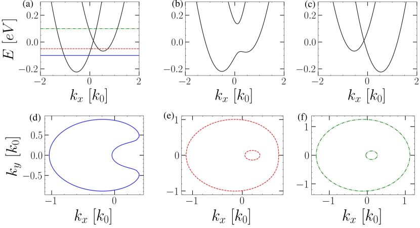
When is nonzero, symmetries associated with , , and are all broken, leading to an asymmetric band structure along the direction (cf. Fig. 2). Specifically, the energy dispersions are
| (23) |
The -component of the velocities are
| (24) |

Here, the potential is assumed to be independent of , predicated on the uniformity of the system along the -direction. This assumption facilitates a simplified solution for the characteristic potential, analogous to the formulation presented in Eq. (16). The LPDOS contains the contribution from all channels and can be expressed as
| (25) |
where represents the LPDOS of the channel in the terminal . In the ballistic limit, where remains a good quantum number and the terminals share the same Hamiltonian as the system, the total transmission is directly evaluated as
| (26) |
where denotes the width of the scattering region in the direction, and are the Heaviside step function and Dirac delta function, respectively. The LPDOS of the left and right terminals can be simplified as
| (27) |
where correspond to respectively. As the temperature approaches zero, becomes proportional to the carrier density of the Fermi arcs for the left- and right-moving modes, as indicated by Eq. (27). When the Fermi surfaces (loops in the 2D case) are asymmetric, as shown in Figs. 2(d-f), . According to Eqs. (16) and (17), nonreciprocal transport phenomena can be expected.

IV.2 Results and Discussions
We start by analyzing the asymmetric energy bands described by Eq. (23), as depicted in Fig. 2. For a given energy in the channel, the velocities of the counter-propagating states are unequal, so as the density of states (DOS). Such band asymmetry necessitates the violation of SIS and TRS which are symmetries , and here. Figs. 2(d-f) reveal the broken reflection symmetry of the Fermi loops about the axis, which gives rise to different characteristic potentials and and leads to the emergence of second-order conductance , as formulated in Eq. (18). In Fig. 3, we plot the characteristic potentials and two conductances . The nonreciprocal transport is revealed by the second-order conductance in Fig. 3(b). According to Eq. (18), it is proportional to the difference of characteristic potentials ; see Fig. 3(c). From Fig. 3(b), one can see that the most pronounced nonreciprocal signals occur at eV, when the Fermi energy coincides with the higher band bottom in Fig. 2(a). It is associated with the von Hove singularity in the density of states (DOS), resulting in a sudden alteration in conductance , as depicted in Fig. 3(a), where the derivative of undergoes an abrupt change at eV. This observation aligns with findings in the diffusive limit Ideue et al. (2017). However, our results in the ballistic limit display persistent non-vanishing signals even when the Fermi energy is above the Dirac point, thus differentiating them from diffusive transport behaviors Ideue et al. (2017).
In Fig. 4, we illustrate how the conductances and first-order potential are influenced by both the Fermi energy and the magnetic field . When is inverted to , the conductance remains unchanged, as does its derivative with respect to energy; see Fig. 4(a). Concurrently, the energy band structure reverses along the direction, as shown in Figs. 2(a) and (c). This reversal swaps the characteristic potentials from to , given that the LPDOS is fully determined by the band structures. This phenomenon is manifested in Fig. 4(c), where the first-order potential is an odd function of for a given . As for Eq. (18), the conductance should also invert its sign, corresponding to the observation in Fig. 4(b). It is noted that the Onsager reciprocal relation Onsager (1931) is violated, as . However, the relation holds, akin to the EMCA effects Rikken et al. (2001); Krstić et al. (2002); Rikken and Wyder (2005).
The resistance formula is commonly adopted in nonreciprocal transport measurements. The expression for resistance, as discussed in Refs. Rikken et al., 2001; Rikken and Wyder, 2005, can be obtained from Eq. (17) as
| (28) |
where
We plot as a function of and in Fig. 4(d). In the funnel-mouth-shaped region, where is relatively small and the Fermi energy lies between the higher band bottom and the Dirac point, appears to be largely independent of . This result coincides with that in the diffusive limit Ideue et al. (2017). However, it is noteworthy that the magnitude of in this region, approximately A-1T-1m, is significantly larger than that reported in Ref. Ideue et al., 2017.
V conclusions
In conclusion, our theoretical investigation focuses on nonreciprocal transport in energy band asymmetric systems within the quantum ballistic regime. A pivotal aspect of our study is the consideration of Coulomb potentials induced by finite biases. Antisymmetric biases at the left and right terminals lead to asymmetric potentials, a consequence of the inherent asymmetry in the band structure. Additionally, our analysis anticipates significantly larger nonreciprocal current signals in the quantum transport regime compared to diffusive bulk materials. We hope that our work will provide valuable insights for future quantum transport experiments.
Acknowledgements.
M. H. Zou and H. Geng contributed equally to this work. This work was supported by the State Key Program for Basic Researches of China under Grants No. 2021YFA1400403 (D.Y.X.), and the National Natural Science Foundation of China under Grant No. 11974168 (L.S.), No. 12174182 (D.Y.X.), No. 12074172 (W.C.), No. 12222406 (W.C.), No. 12274235 (R.M.), and No. 12304068 (H. G.).References
- Tokura and Nagaosa (2018) Y. Tokura and N. Nagaosa, Nature Communications 9, 3740 (2018).
- Ideue and Iwasa (2021) T. Ideue and Y. Iwasa, Annual Review of Condensed Matter Physics 12, 201 (2021), https://doi.org/10.1146/annurev-conmatphys-060220-100347 .
- Fruchart et al. (2021) M. Fruchart, R. Hanai, P. B. Littlewood, and V. Vitelli, Nature 592, 363 (2021).
- Akamatsu et al. (2021) T. Akamatsu, T. Ideue, L. Zhou, Y. Dong, S. Kitamura, M. Yoshii, D. Yang, M. Onga, Y. Nakagawa, K. Watanabe, T. Taniguchi, J. Laurienzo, J. Huang, Z. Ye, T. Morimoto, H. Yuan, and Y. Iwasa, Science 372, 68 (2021).
- Rikken et al. (2001) G. Rikken, J. Fölling, and P. Wyder, Physical Review Letters 87, 236602 (2001).
- Krstić et al. (2002) V. Krstić, S. Roth, M. Burghard, K. Kern, and G. L. J. A. Rikken, The Journal of Chemical Physics 117, 11315 (2002).
- Ideue et al. (2017) T. Ideue, K. Hamamoto, S. Koshikawa, M. Ezawa, S. Shimizu, Y. Kaneko, Y. Tokura, N. Nagaosa, and Y. Iwasa, Nature Physics 13, 578 (2017).
- Itahashi et al. (2020) Y. M. Itahashi, T. Ideue, Y. Saito, S. Shimizu, T. Ouchi, T. Nojima, and Y. Iwasa, Science Advances 6, eaay9120 (2020).
- Li et al. (2021) Y. Li, Y. Li, P. Li, B. Fang, X. Yang, Y. Wen, D.-x. Zheng, C.-h. Zhang, X. He, A. Manchon, Z.-H. Cheng, and X.-x. Zhang, Nature Communications 12, 540 (2021).
- Avci et al. (2015) C. O. Avci, K. Garello, A. Ghosh, M. Gabureac, S. F. Alvarado, and P. Gambardella, Nature Physics 11, 570 (2015).
- Yasuda et al. (2019) K. Yasuda, H. Yasuda, T. Liang, R. Yoshimi, A. Tsukazaki, K. S. Takahashi, N. Nagaosa, M. Kawasaki, and Y. Tokura, Nature Communications 10, 2734 (2019).
- Choe et al. (2019) D. Choe, M.-J. Jin, S.-I. Kim, H.-J. Choi, J. Jo, I. Oh, J. Park, H. Jin, H. C. Koo, B.-C. Min, S. Hong, H.-W. Lee, S.-H. Baek, and J.-W. Yoo, Nature Communications 10, 4510 (2019).
- Shim et al. (2022) S. Shim, M. Mehraeen, J. Sklenar, J. Oh, J. Gibbons, H. Saglam, A. Hoffmann, S. S.-L. Zhang, and N. Mason, Phys. Rev. X 12, 021069 (2022).
- Ye et al. (2022) C. Ye, X. Xie, W. Lv, K. Huang, A. J. Yang, S. Jiang, X. Liu, D. Zhu, X. Qiu, M. Tong, T. Zhou, C.-H. Hsu, G. Chang, H. Lin, P. Li, K. Yang, Z. Wang, T. Jiang, and X. Renshaw Wang, Nano Letters 22, 1366 (2022).
- Yasuda et al. (2020) K. Yasuda, T. Morimoto, R. Yoshimi, M. Mogi, A. Tsukazaki, M. Kawamura, K. S. Takahashi, M. Kawasaki, N. Nagaosa, and Y. Tokura, Nature Nanotechnology 15, 831 (2020).
- Zhang et al. (2022) Z. Zhang, N. Wang, N. Cao, A. Wang, X. Zhou, K. Watanabe, T. Taniguchi, B. Yan, and W.-b. Gao, Nature Communications 13, 6191 (2022).
- Ishizuka and Nagaosa (2020) H. Ishizuka and N. Nagaosa, Nature Communications 11, 2986 (2020).
- Yasuda et al. (2016) K. Yasuda, A. Tsukazaki, R. Yoshimi, K. S. Takahashi, M. Kawasaki, and Y. Tokura, Phys. Rev. Lett. 117, 127202 (2016).
- Kaplan et al. (2022) D. Kaplan, T. Holder, and B. Yan, arXiv preprint arXiv:2211.17213 (2022).
- Wang et al. (2023) N. Wang, D. Kaplan, Z. Zhang, T. Holder, N. Cao, A. Wang, X. Zhou, F. Zhou, Z. Jiang, C. Zhang, S. Ru, H. Cai, K. Watanabe, T. Taniguchi, B. Yan, and W. Gao, Nature , 1 (2023).
- Geng et al. (2023) H. Geng, J. Y. Wei, M. H. Zou, L. Sheng, W. Chen, and D. Y. Xing, Phys. Rev. B 107, 035306 (2023).
- Shao et al. (2023) K. Shao, H. Geng, E. Liu, J. L. Lado, W. Chen, and D. Y. Xing, A Non-Hermitian Moiré Valley Filter, Tech. Rep. (2023) arXiv:2310.10973 [cond-mat] type: article.
- Zhang and Vignale (2016) S. S.-L. Zhang and G. Vignale, Phys. Rev. B 94, 140411 (2016).
- Sterk et al. (2019) W. P. Sterk, D. Peerlings, and R. A. Duine, Phys. Rev. B 99, 064438 (2019).
- Freimuth et al. (2021) F. Freimuth, S. Blügel, and Y. Mokrousov, Journal of Physics: Condensed Matter 34, 055301 (2021).
- Büttiker et al. (1993) M. Büttiker, A. Prêtre, and H. Thomas, Phys. Rev. Lett. 70, 4114 (1993).
- Büttiker (1995) M. Büttiker, “Charge and current conserving mesoscopic transport,” in Quantum Dynamics of Submicron Structures, edited by H. A. Cerdeira, B. Kramer, and G. Schön (Springer Netherlands, Dordrecht, 1995) pp. 657–672.
- Christen and Büttiker (1996) T. Christen and M. Büttiker, Europhysics Letters 35, 523 (1996).
- Onsager (1931) L. Onsager, Phys. Rev. 37, 405 (1931).
- Rikken and Wyder (2005) G. L. J. A. Rikken and P. Wyder, Phys. Rev. Lett. 94, 016601 (2005).
- Jauho et al. (1994) A.-P. Jauho, N. S. Wingreen, and Y. Meir, Phys. Rev. B 50, 5528 (1994).
- Anantram and Datta (1995) M. P. Anantram and S. Datta, Phys. Rev. B 51, 7632 (1995).
- Datta (2005) S. Datta, Quantum transport: atom to transistor (Cambridge university press, 2005).
- Bruus and Flensberg (2004) H. Bruus and K. Flensberg, Many-body quantum theory in condensed matter physics: an introduction (OUP Oxford, 2004).
- Wang et al. (1999) B. Wang, J. Wang, and H. Guo, Journal of Applied Physics 86, 5094 (1999).
- Buttiker (1993) M. Buttiker, Journal of Physics: Condensed Matter 5, 9361 (1993).
- Wang et al. (1997) J. Wang, Q. Zheng, and H. Guo, Phys. Rev. B 55, 9763 (1997).
- Kramer (2012) B. Kramer, Quantum transport in semiconductor submicron structures, Vol. 326 (Springer Science & Business Media, 2012).
- Wei et al. (2022) M. Wei, B. Wang, Y. Yu, F. Xu, and J. Wang, Phys. Rev. B 105, 115411 (2022).
- Sheng et al. (1998) W.-D. Sheng, J. Wang, and H. Guo, Journal of Physics: Condensed Matter 10, 5335 (1998).
- Song et al. (1998) A. M. Song, A. Lorke, A. Kriele, J. P. Kotthaus, W. Wegscheider, and M. Bichler, Phys. Rev. Lett. 80, 3831 (1998).
- Varjas et al. (2018) D. Varjas, T. Ö. Rosdahl, and A. R. Akhmerov, New Journal of Physics 20, 093026 (2018).