Towards an experimental proof of the magnonic Aharonov–Casher effect
Abstract
Controlling the phase and amplitude of spin waves in magnetic insulators with an electric field opens the way to fast logic circuits with ultra-low power consumption. One way to achieve such control is to manipulate the magnetization of the medium via magnetoelectric effects. In experiments with magnetostatic spin waves in an yttrium iron garnet film, we have obtained the first evidence of a theoretically predicted phenomenon: The change of the spin-wave phase due to the magnonic Aharonov–Casher effect—the geometric accumulation of the magnon phase as these quasiparticles propagate through an electric field region.
Magnonics, a research branch in the field of magnetism [1, 2, 3, 4], offers a promising chance to overcome the challenges of modern complementary metal-oxide-semiconductor (CMOS) technology [5]. Unlike conventional electronics, which uses voltage-controlled charge currents to process data, magnonics employs magnons, bosonic quasiparticles of collective spin oscillations—spin waves [4]. Magnons transport energy and magnetic moment in the form of a charge-free spin current [6] without Joule heating and with wavelengths down to the nanoscale [7, 8]. The latter allows us to imagine a strong miniaturization of future magnon-based data processing circuits [9]. These collective excitations in magnetically ordered materials provide conventional wave properties such as interference, as well as the quantum nature properties of quasiparticles with nonlinearity and Bose–Einstein condensation capability [10, 11, 12], making them ideal data carriers for future computing concepts [13, 14, 15, 16, 17].
Magnonics enables wave logic, which exploits the superposition of coherent waves involving linear and nonlinear effects. Therefore, phase control of spin waves is an important issue. Furthermore, to transport and process information [15], it has been proposed to use macroscopic magnon quantum phenomena, such as the room-temperature magnon Bose–Einstein condensate (BEC) and magnon supercurrents, which are phase-induced collective motions of quantum condensates [18]. This approach requires precise control of the magnon BEC phase.
Already, success has been achieved in controlling the spin-wave phase using various magnetoelectric (ME) effects [19, 20, 21]. Methods to excite [22, 23] and modulate [24] spin waves via the ME effects, based on magnetostriction and piezoelectricity, were elaborated. Another intensively investigated ME effect is the voltage-controlled magnetic anisotropy, which influences the surface layer properties of ferromagnets [25, 26, 27]. This phenomenon was already used to excite spin waves and oscillations [28, 29, 30] and to shift their resonance frequency [31]. The possibility of a ME-controlled frequency and phase shift of a spin wave propagating in a magnetic insulator, namely, in yttrium iron garnet (Y3Fe5O12, YIG), a material that is widely used in magnonics due to its lowest known magnetic losses [32, 33, 4], was analyzed theoretically [34] and realized experimentally [35, 36, 37].
Another approach, motivating from both a purely scientific and a practical point of view, is using the Aharonov–Casher (AC) effect [38, 39, 40, 41, 42, 43]. This effect lies in the geometric accumulation of the wave function’s phase as particles with magnetic moments pass through an electric field region:
| (1) |
Here, , , and are the AC phase, the external electric field, the speed of light and the magnetic moment of a (quasi-) particle moving along the path [40].
This phenomenon has been observed for real particles [44] and theoretically predicted for quasiparticles such as magnons [45]. Moreover, the AC effect is believed to be applied even to magnons with zero group velocity. Thus, it can be used to create and control persistent currents of a magnon BEC [46, 47].
However, the previous studies [35] on manipulating the magnon phase in YIG using an electric field did not allow one to distinguish the AC effect from the contribution of ME effects. It is related to the expectedly small influence of the AC effect on the long-wave magnetostatic spin waves studied in the experiment [39].
Here, we report experimental results in favor of the existence of the magnonic Aharonov–Casher effect. These results were obtained in an experiment with surface and backward volume magnetostatic spin waves propagating in an in-plane magnetized YIG film. Using two types of magnetostatic waves propagating perpendicular and parallel to the film magnetization direction, and thus differently affected by the AC effect, allowed us to reveal a contribution to the electric field-induced phase shift, which we attribute to the AC phase.
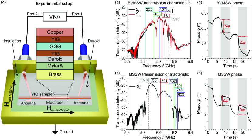
The experimental setup is shown schematically in Fig. 1a. The YIG sample contains a 7.8 m-thick YIG film grown by liquid-phase epitaxy on a 500 m-thick gallium gadolinium garnet substrate in the (111) plane. It is cut as a 41 mm-long and 2 mm-wide strip, which is oriented along the direction and acts as a waveguide for spin waves. In the experiment, the YIG strip was magnetized by an external magnetic field both along and perpendicular to its long axis to provide backward volume magnetostatic spin waves (BVMSW) and magnetostatic surface spin waves (MSSW) geometries, respectively. To minimize phase jumps and drifts, this field was created by a permanent magnet located together with the setup in a temperature-stabilized environment.
The YIG film faces a pair of 50 m-wide microstrip spin-wave antennas spaced 16 mm apart. The antennas are chemically etched on a 350 m-thick plate of copper-laminated ceramic-PTFE composite Rogers RT/duroid® with the dielectric constant . The spin wave excited by the microwave magnetic field of one of the antennas propagates through the YIG film to the second one, where it is received and measured. A vector network analyzer (VNA) Anritsu MS4642B was used as a microwave source and a precise phase-resolved microwave detector.
The inset in Fig. 1b shows the multilayer structure in the area where the electric field is applied. At the bottom is a grounded brass sample holder. On top of it is an insulating layer of 500 m-thick MylarA® (PET plastic). It is followed by the 320 m-thick duroid® layer carrying the microstrip antennas, and on top of that is a 516 m thick YIG/GGG/YIG sample. Finally, a 20 m-thick, 10 mm-long, and 1.5 mm-wide copper electrode is glued to the sample’s surface and connected to the high-voltage source (Advanced Energy 60C24-P60-I5). Considering the glue between the layers, the applied voltage creates an electric field at a distance of mm. The electrode, sample, and antennas were coated with a thin superglue layer, allowing the safe application of electric fields of up to 6 kV/mm.
First, for a given magnetic field , the intensity of the output signal was measured as a function of frequency, and several frequencies were selected for phase observations (see Figs. 1b and 1c).
Next, the phase and amplitude of the output signal were measured using the VNA in quasi-oscilloscope mode at fixed frequencies for a large number of consecutive points in time.
In this operating mode, the electric voltage was switched on and off several times during the VNA sweep. The phase difference between the time intervals when the electric field was on and off (see Figs. 1d and 1e) is considered as the electrically-induced phase shift . The temporal behavior of the phase switching is mainly determined by the characteristics of the high-voltage source.
Initially, the measurements were performed in the BVMSW geometry when magnons propagate along . When an electric field is applied, a negative phase shift is observed, as shown in Fig. 1d. The phase shifts of BVMSWs propagating in opposite directions are the same within the 95% confidence interval. Their mean values are plotted in Fig. 2a as a function of the electric field strength .
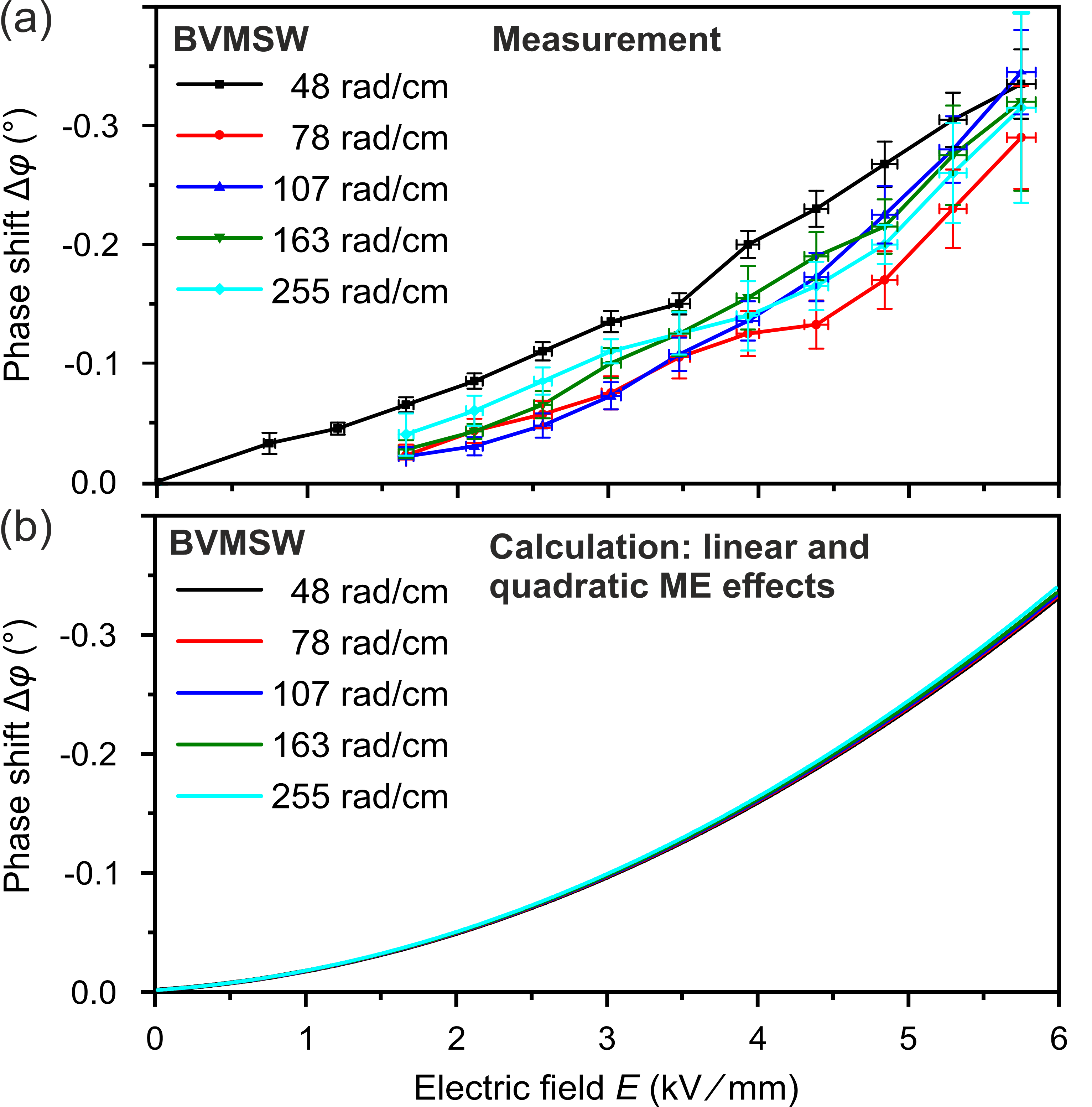
The measurements were carried out at five different frequencies and, accordingly, different BVMSW wavevectors. Figure 2a shows that the phase shift is rather small (°) and can be considered independent of the magnon wavevector. While the strongest shifts, shown by the black curve, are observed for the wavevector value rad/cm, and the smallest, shown by the red curve, are for rad/cm, the other three dependencies for larger are in between. Moreover, these three curves are mostly within each other’s error bars. From the shape of the curves in Fig. 2a, the phase shift seems to have a quadratic dependence on .
The increase in measurement errors with increasing is due to a decrease in spin wave transmission, as is shown in Fig. 1b. This reduction limits the maximum available wavevector value to rad/cm. Phase noise also made it impossible to measure the phase shift for electric fields below kV/mm, except for the strongest spin wave with the smallest wavevector.
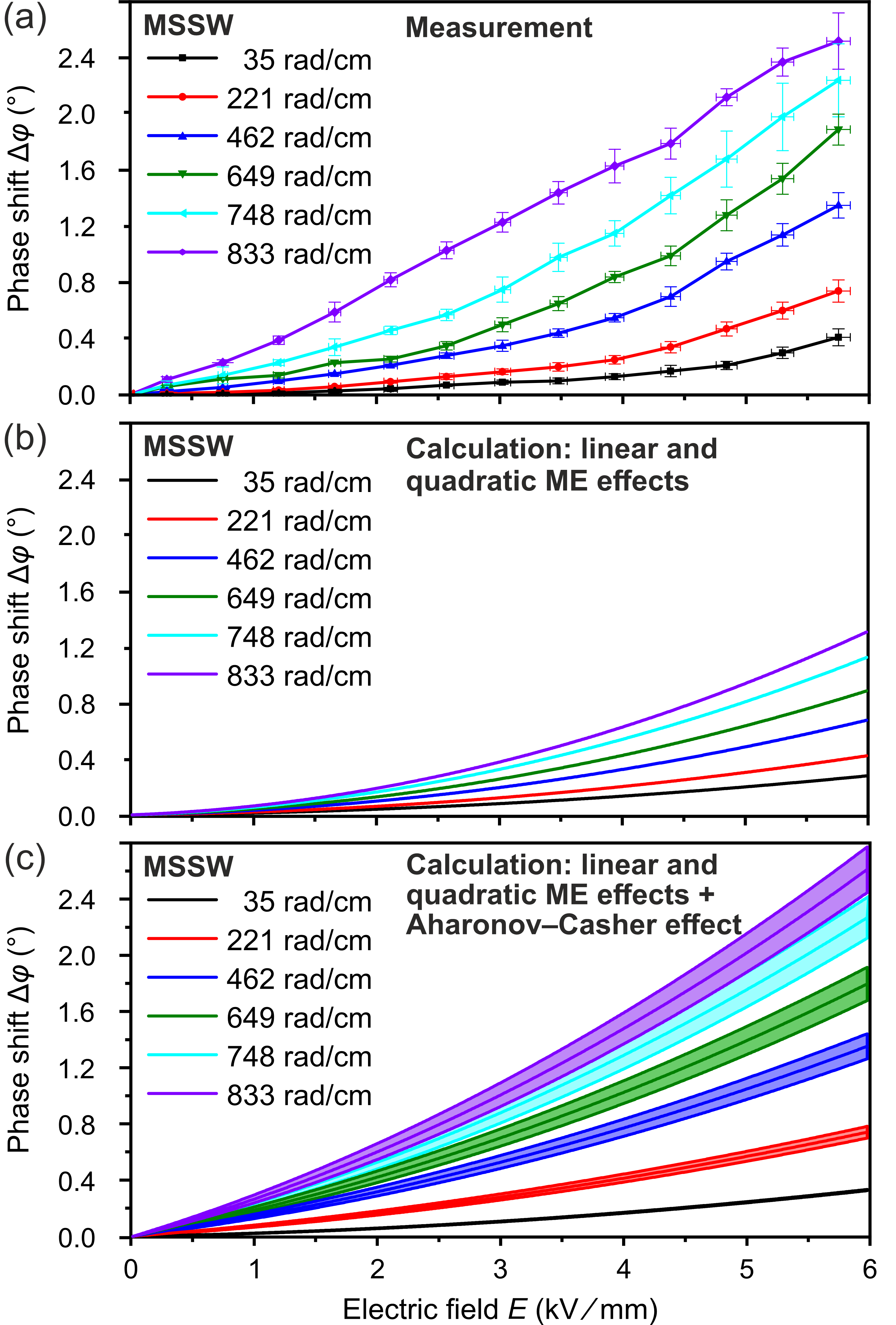
The second series of measurements concerns MSSWs. In this geometry, the wavevector is perpendicular to , and is perpendicular to both. The phase-shift measurement example in Fig. 1e shows that is positive in this case. The difference in the sign of the phase shifts of MSSW and BVMSW is due to the opposite directions of the group velocities of these two types of waves. Since MSSWs are excited nonreciprocally [48], only for one propagation direction can be measured. The corresponding transmission characteristic S12 is shown in Fig. 1c together with the six frequencies chosen for the measurements and the corresponding calculated values of the MSSW wavevector . The broader bandwidth of the MSSW allows the use of much higher wavevectors for measurements than in the BWMSW case.
The phase-shift results are depicted in Fig. 3a. It becomes visible, that strongly depends on . While the maximum for the smallest wavevector rad/cm is only about 0.4°, the maximum for the largest rad/cm exceeds 2.5°. The dependencies for other wavevectors are located between these curves in ascending order of . Also, all phase curves, except the violet one, similar to the BVMSW case, have a clear quadratic dependence on the applied electric field for kV/mm. We can assume that this results from the quadratic ME effect in YIG.
The YIG saturation magnetization changes quadratically with respect to into a direction determined by a third rank tensor [49, 50]. Unfortunately, the tensor coefficient 113 responsible for the magnetization change in the given geometry ( and ) is unknown. However, it is known that all these tensor coefficients are very small on the order of Am-1V-2m2 [51]. This leads to only a tiny change in magnetization of about 6 A/m for the maximal electric field in our experiment, while for YIG kA/m at room temperature. Thus, it can be assumed that the change in the direction of magnetization caused by the electric field is negligible, and only a change should be considered.
It can be also assumed that the YIG sample may also have a linear ME response in an electric field. In the ideal cubic YIG lattice, no linear response exists. However, in real YIG samples it is possible due to reduced crystal symmetry caused by the film shape, impurities, or a mismatch with the crystal lattice of the substrate [52, 53]. The coefficients for this effect are also unknown and are likely to be highly dependent on the quality and thickness of YIG films.
The change in spin-wave energy caused by the Aharonov–Casher effect can be approximated as
| (2) |
where with the exchange integral is a factor characterizing the spin-orbit interaction in vacuum, while describes the energy of interaction between the magnon magnetic moment and an electric field [43]. Equation (2) limits the possible spin-wave geometries available for the AC effect in our experiment since for BVMSW, when , the AC effect is expected to be very small, if not wholly vanishing. On the contrary, the MSSW geometry provides the maximum interaction with because is parallel to in this case. This difference allowed us to determine the contribution of ME effects and distinguish the AC phase in the overall electrically induced phase shift of MSSW.
First, we have fitted the linear and quadratic ME coefficients for the BVMSW modes, neglecting the AC effect. The least-squares fit minimizes the difference between our experimental data and the phase shift resulting from the ME-induced magnetization change in the BVMSW dispersion relation (see Eq. (5.97a) in Ref. [54])
| (3) | ||||
Here, GHz T-1, , is the film thickness, is the spin-wave propagation length in the electric field region, and .
These fits yielded the average values of the quadratic ME coefficient Am-1V-2m2 and the linear ME coefficient Am-1V-1m. The calculated phase-shift dependencies are shown in Fig. 2b. They agree with the measured phase shifts in shape and sign. Changing the wavevector in the range of values available in the experiment (48 – 255 rad/cm) has a minimal effect on the course of these curves. This is consistent with the fact that the difference in the experimental curves looks arbitrary and has no stable relationship with the wavevector magnitude.
Subsequently, we used the fitted coefficients to calculate the phase shifts of MSSWs using the following dispertion relation (see Eq. (5.111c) in Ref. [54]):
| (4) |
The calculated phase shifts were compared with the experimental data to assess the contribution of the AC phase. This is possible because, in theory, the quadratic ME coefficients are the same in both cases (see Eq. 6 in Ref. [49]). It is also assumed that the potential contribution of the linear effect of ME is at least very close in both cases. The latter assumption is related to the fact that the ME effect arises due to the reduction of crystal symmetry in the film. However, since the well-studied uniaxial magnetic anisotropy has the same origin [55], it can also be assumed that in the case of the linear ME effect, it acquires similar properties and can be described by identical coefficients for the MSSW and BVMSW geometries.
The calculated MSSW phase-shift dependencies are presented in Fig. 3b. Like the experimental data in Fig. 3a, they feature a positive phase shift. However, the calculated phase shifts are much smaller than the measured ones and are only about 40% of them for the four largest wavevectors.
It seems that in the case of MSSWs, there is indeed an additional contribution, which causes a more significant phase shift than the ME effects addressed. Thus, the next step is to consider the influence of the AC effect on MSSWs. In this paper, this is done empirically by adding a linear phase shift term that depends on the electric field and the spin-wave wavevector:
| (5) |
Here, is the change in the MSSW wavevector induced by the ME effects, and is the empirical AC coefficient with unit kV-1. Using the same ME coefficients and fitting for each of the four largest wavevectors that show a significant deviation from the experimental results, we calculate the average value of , which is used in the new phase-shift calculations for all wavevector values. The results of these calculations are shown in Fig. 3c and can be compared with the experimental data in Fig. 3a. The average value of is kV-1, but since there are variations in the fitting values for individual wavevectors, we decided to show the bands formed by the highest kV-1 and the lowest kV-1 fitting values. The obtained bands are in good agreement with the measured curves. It should be noted that the curves calculated for large are more sensitive to variations in the AC coefficient . This is evident from the width of the bands.
The good agreement of our estimations with experimental data indicates that MSSW magnons can accumulate an additional phase due to interaction with the electric field through the magnonic Aharonov–Casher effect. At the same time, additional experiments are needed to check the nonreciprocity of this difference upon inversion of electric or magnetic fields or the direction of spin-wave propagation.
In further experimental studies of this phenomenon, it seems advisable to use short-wave spin waves and microscopic interelectrode gaps. This will increase the AC phase and allow controlling it with a moderate external voltage. Notably, the quadratic ME effect in YIG films makes it unnecessary to apply excessively high electric fields, at which the phase shift caused by this effect significantly exceeds the AC phase. Success in this direction may lead to the observation of such manifestations of the magnonic Aharonov–Casher effect as persistent spin currents [51, 46], electrically induced refraction [56], non-reciprocity [57], anisotropy and caustics [41, 42] of exchange spin waves, and thus will allow the implementation of electrically controlled magnon optics and logic devices [39]. This effect can also lead to magnon topological phases in insulating antiferromagnets [58] and to the magnonic quantum Hall effect [59]. It can be employed for the generation of twisted magnon beams carrying an electrically controllable orbital angular momentum [60]. The implications of the magnonic Aharonov–Casher effect look particularly intriguing and exciting when the electric field is time-dependent and periodic [61].
This research was funded by the European Research Council within the Advanced Grant No. 694709 “SuperMagnonics.” The authors are grateful to R.V. Verba, V.S. L’vov, and M. Weiler for fruitful discussions.
References
- Kruglyak et al. [2010] V. V. Kruglyak, S. O. Demokritov, and D. Grundler, Magnonics, J. Phys. D: Appl. Phys. 43, 260301 (2010).
- Lenk et al. [2011] B. Lenk, H. Ulrichs, F. Garbs, and M. Münzenberg, The building blocks of magnonics, Phys. Rep. 507, 107 (2011).
- Chumak et al. [2015] A. V. Chumak, V. I. Vasyuchka, A. A. Serga, and B. Hillebrands, Magnon spintronics, Nat. Phys. 11, 453 (2015).
- Pirro et al. [2021] P. Pirro, V. I. Vasyuchka, A. A. Serga, and B. Hillebrands, Advances in coherent magnonics, Nat. Rev. Mater. 6, 1114 (2021).
- Barman et al. [2021] A. Barman, G. Gubbiotti, S. Ladak, A. O. Adeyeye, M. Krawczyk, J. Gräfe, C. Adelmann, S. Cotofana, A. Naeemi, V. I. Vasyuchka, B. Hillebrands, S. A. Nikitov, H. Yu, D. Grundler, A. V. Sadovnikov, A. A. Grachev, S. E. Sheshukova, J.-Y. Duquesne, M. Marangolo, G. Csaba, W. Porod, V. E. Demidov, S. Urazhdin, S. O. Demokritov, E. Albisetti, D. Petti, R. Bertacco, H. Schultheiss, V. V. Kruglyak, V. D. Poimanov, S. Sahoo, J. Sinha, H. Yang, M. Münzenberg, T. Moriyama, S. Mizukami, P. Landeros, R. A. Gallardo, G. Carlotti, J.-V. Kim, R. L. Stamps, R. E. Camley, B. Rana, Y. Otani, W. Yu, T. Yu, G. E. W. Bauer, C. Back, G. S. Uhrig, O. V. Dobrovolskiy, B. Budinska, H. Qin, S. van Dijken, A. V. Chumak, A. Khitun, D. E. Nikonov, I. A. Young, B. W. Zingsem, and M. Winklhofer, The 2021 magnonics roadmap, J. Phys. Condens. Matter. 33, 413001 (2021).
- Maekawa et al. [2023] S. Maekawa, T. Kikkawa, H. Chudo, J. Ieda, and E. Saitoh, Spin and spin current—From fundamentals to recent progress, J. Appl. Phys. 133, 020902 (2023).
- Che et al. [2020] P. Che, K. Baumgaertl, A. Kúkol’ová, C. Dubs, and D. Grundler, Efficient wavelength conversion of exchange magnons below 100 nm by magnetic coplanar waveguides, Nat. Commun. 11, 1445 (2020).
- Dieterle et al. [2019] G. Dieterle, J. Förster, H. Stoll, A. S. Semisalova, S. Finizio, A. Gangwar, M. Weigand, M. Noske, M. Fähnle, I. Bykova, J. Gräfe, D. A. Bozhko, H. Y. Musiienko-Shmarova, V. Tiberkevich, A. N. Slavin, C. H. Back, J. Raabe, G. Schütz, and S. Wintz, Coherent excitation of heterosymmetric spin waves with ultrashort wavelengths, Phys. Rev. Lett. 122, 117202 (2019).
- Heinz et al. [2022] B. Heinz, M. Mohseni, A. Lentfert, R. Verba, M. Schneider, B. Lägel, K. Levchenko, T. Brächer, C. Dubs, A. V. Chumak, and P. Pirro, Parametric generation of spin waves in nanoscaled magnonic conduits, Phys. Rev. B 105, 144424 (2022).
- Demokritov et al. [2006] S. O. Demokritov, V. E. Demidov, O. Dzyapko, G. A. Melkov, A. A. Serga, B. Hillebrands, and A. N. Slavin, Bose–Einstein condensation of quasi-equilibrium magnons at room temperature under pumping, Nature 443, 430 (2006).
- Serga et al. [2014] A. A. Serga, V. S. Tiberkevich, C. W. Sandweg, V. I. Vasyuchka, D. A. Bozhko, A. V. Chumak, T. Neumann, B. Obry, G. A. Melkov, A. N. Slavin, and B. Hillebrands, Bose–Einstein condensation in an ultra-hot gas of pumped magnons, Nat. Commun. 5, 3452 (2014).
- Schneider et al. [2020] M. Schneider, T. Brächer, D. Breitbach, V. Lauer, P. Pirro, D. A. Bozhko, H. Y. Musiienko-Shmarova, B. Heinz, Q. Wang, T. Meyer, F. Heussner, S. Keller, E. T. Papaioannou, B. Lägel, T. Löber, C. Dubs, A. N. Slavin, V. S. Tiberkevich, A. A. Serga, B. Hillebrands, and A. V. Chumak, Bose–Einstein condensation of quasiparticles by rapid cooling, Nat. Nanotechnol. 15, 457 (2020).
- Chumak et al. [2022] A. V. Chumak, P. Kabos, M. Wu, C. Abert, C. Adelmann, A. O. Adeyeye, J. Akerman, F. G. Aliev, A. Anane, A. Awad, C. H. Back, A. Barman, G. E. W. Bauer, M. Becherer, E. N. Beginin, V. A. S. V. Bittencourt, Y. M. Blanter, P. Bortolotti, I. Boventer, D. A. Bozhko, S. A. Bunyaev, J. J. Carmiggelt, R. R. Cheenikundil, F. Ciubotaru, S. Cotofana, G. Csaba, O. V. Dobrovolskiy, C. Dubs, M. Elyasi, K. G. Fripp, H. Fulara, I. A. Golovchanskiy, C. Gonzalez-Ballestero, P. Graczyk, D. Grundler, P. Gruszecki, G. Gubbiotti, K. Guslienko, A. Haldar, S. Hamdioui, R. Hertel, B. Hillebrands, T. Hioki, A. Houshang, C.-M. Hu, H. Huebl, M. Huth, E. Iacocca, M. B. Jungfleisch, G. N. Kakazei, A. Khitun, R. Khymyn, T. Kikkawa, M. Klaui, O. Klein, J. W. Klos, S. Knauer, S. Koraltan, M. Kostylev, M. Krawczyk, I. N. Krivorotov, V. V. Kruglyak, D. Lachance-Quirion, S. Ladak, R. Lebrun, Y. Li, M. Lindner, R. Macedo, S. Mayr, G. A. Melkov, S. Mieszczak, Y. Nakamura, H. T. Nembach, A. A. Nikitin, S. A. Nikitov, V. Novosad, J. A. Otalora, Y. Otani, A. Papp, B. Pigeau, P. Pirro, W. Porod, F. Porrati, H. Qin, B. Rana, T. Reimann, F. Riente, O. Romero-Isart, A. Ross, A. V. Sadovnikov, A. R. Safin, E. Saitoh, G. Schmidt, H. Schultheiss, K. Schultheiss, A. A. Serga, S. Sharma, J. M. Shaw, D. Suess, O. Surzhenko, K. Szulc, T. Taniguchi, M. Urbanek, K. Usami, A. B. Ustinov, T. van der Sar, S. van Dijken, V. I. Vasyuchka, R. Verba, S. V. Kusminskiy, Q. Wang, M. Weides, M. Weiler, S. Wintz, S. P. Wolski, and X. Zhang, Advances in magnetics: Roadmap on spin-wave computing, IEEE Trans. Magn. 58, 0800172 (2022).
- Dieny et al. [2020] B. Dieny, I. L. Prejbeanu, K. Garello, P. Gambardella, P. Freitas, R. Lehndorff, W. Raberg, U. Ebels, S. O. Demokritov, J. Akerman, A. Deac, P. Pirro, C. Adelmann, A. Anane, A. V. Chumak, A. Hirohata, S. Mangin, S. O. Valenzuela, M. C. Onbaşlı, M. d’Aquino, G. Prenat, G. Finocchio, L. Lopez-Diaz, R. Chantrell, O. Chubykalo-Fesenko, and P. Bortolotti, Opportunities and challenges for spintronics in the microelectronics industry, Nat. Electron. 3, 446 (2020).
- Mohseni et al. [2022] M. Mohseni, V. I. Vasyuchka, V. S. L’vov, A. A. Serga, and B. Hillebrands, Classical analog of qubit logic based on a magnon Bose–Einstein condensate, Commun. Phys. 5, 196 (2022).
- Csaba et al. [2017] G. Csaba, Á. Papp, and W. Porod, Perspectives of using spin waves for computing and signal processing, Phys. Lett. A 381, 1471 (2017).
- Khitun et al. [2010] A. Khitun, M. Bao, and K. L. Wang, Magnonic logic circuits, J. Phys. D: Appl. Phys. 43, 264005 (2010).
- Bozhko et al. [2019] D. A. Bozhko, A. J. E. Kreil, H. Y. Musiienko-Shmarova, A. A. Serga, A. Pomyalov, V. S. L’vov, and B. Hillebrands, Bogoliubov waves and distant transport of magnon condensate at room temperature, Nat. Commun. 10, 2460 (2019).
- Fiebig [2005] M. Fiebig, Revival of the magnetoelectric effect, J. Phys. D: Appl. Phys. 38, R123 (2005).
- Matsukura et al. [2015] F. Matsukura, Y. Tokura, and H. Ohno, Control of magnetism by electric fields, Nat. Nanotechnol. 10, 209 (2015).
- Hirosawa et al. [2022] T. Hirosawa, A. Mook, J. Klinovaja, and D. Loss, Magnetoelectric cavity magnonics in skyrmion crystals, PRX Quantum 3, 040321 (2022).
- Cherepov et al. [2014] S. Cherepov, P. K. Amiri, J. G. Alzate, K. Wong, M. Lewis, P. Upadhyaya, J. Nath, M. Bao, A. Bur, T. Wu, G. P. Carman, A. Khitun, and K. L. Wang, Electric-field-induced spin wave generation using multiferroic magnetoelectric cells, Appl. Phys. Lett. 104, 082403 (2014).
- Vanderveken et al. [2020] F. Vanderveken, H. Ahmad, M. Heyns, B. Sorée, C. Adelmann, and F. Ciubotaru, Excitation and propagation of spin waves in non-uniformly magnetized waveguides, J. Phys. D: Appl. Phys 53, 495006 (2020).
- Balinskiy et al. [2018] M. Balinskiy, A. C. Chavez, A. Barra, H. Chiang, G. P. Carman, and A. Khitun, Magnetoelectric spin wave modulator based on synthetic multiferroic structure, Sci. Rep. 8, 10867 (2018).
- Miwa et al. [2018] S. Miwa, M. Suzuki, M. Tsujikawa, T. Nozaki, T. Nakamura, M. Shirai, S. Yuasa, and Y. Suzuki, Perpendicular magnetic anisotropy and its electric-field-induced change at metal-dielectric interfaces, J. Phys. D: Appl. Phys. 52, 063001 (2018).
- Endo et al. [2010] M. Endo, S. Kanai, S. Ikeda, F. Matsukura, and H. Ohno, Electric-field effects on thickness dependent magnetic anisotropy of sputtered MgO/Co40Fe40B20/Ta structures, Appl. Phys. Lett. 96, 212503 (2010).
- Weisheit et al. [2007] M. Weisheit, S. Fähler, A. Marty, Y. Souche, C. Poinsignon, and D. Givord, Electric field-induced modification of magnetism in thin-film ferromagnets, Science 315, 349 (2007).
- Verba et al. [2014] R. Verba, V. Tiberkevich, I. Krivorotov, and A. Slavin, Parametric excitation of spin waves by voltage-controlled magnetic anisotropy, Phys. Rev. Applied 1, 044006 (2014).
- Nozaki et al. [2012] T. Nozaki, Y. Shiota, S. Miwa, S. Murakami, F. Bonell, S. Ishibashi, H. Kubota, K. Yakushiji, T. Saruya, A. Fukushima, S. Yuasa, T. Shinjo, and Y. Suzuki, Electric-field-induced ferromagnetic resonance excitation in an ultrathin ferromagnetic metal layer, Nat. Phys. 8, 491 (2012).
- Zhu et al. [2012] J. Zhu, J. A. Katine, G. E. Rowlands, Y.-J. Chen, Z. Duan, J. G. Alzate, P. Upadhyaya, J. Langer, P. K. Amiri, K. L. Wang, and I. N. Krivorotov, Voltage-induced ferromagnetic resonance in magnetic tunnel junctions, Phys. Rev. Lett. 108, 197203 (2012).
- Ha et al. [2010] S.-S. Ha, N.-H. Kim, S. Lee, C.-Y. You, Y. Shiota, T. Maruyama, T. Nozaki, and Y. Suzuki, Voltage induced magnetic anisotropy change in ultrathin Fe80Co20/MgO junctions with Brillouin light scattering, Appl. Phys. Lett. 96, 142512 (2010).
- Cherepanov et al. [1993] V. Cherepanov, I. Kolokolov, and V. L'vov, The saga of YIG: Spectra, thermodynamics, interaction and relaxation of magnons in a complex magnet, Phys. Rep. 229, 81 (1993).
- Serga et al. [2010] A. A. Serga, A. V. Chumak, and B. Hillebrands, YIG magnonics, J. Phys. D: Appl. Phys. 43, 264002 (2010).
- Wang et al. [2018] X. Wang, L. Chotorlishvili, G. Guo, and J. Berakdar, Electric field controlled spin waveguide phase shifter in YIG, J. Appl. Phys. 124, 073903 (2018).
- Zhang et al. [2014] X. Zhang, T. Liu, M. E. Flatté, and H. X. Tang, Electric-field coupling to spin waves in a centrosymmetric ferrite, Phys. Rev. Lett. 113, 037202 (2014).
- Ustinov et al. [2019] A. B. Ustinov, A. V. Drozdovskii, A. A. Nikitin, A. A. Semenov, D. A. Bozhko, A. A. Serga, B. Hillebrands, E. Lähderanta, and B. A. Kalinikos, Dynamic electromagnonic crystal based on artificial multiferroic heterostructure, Commun. Phys. 2, 137 (2019).
- Yu et al. [2019] R. Yu, K. He, Q. Liu, X. Gan, B. Miao, L. Sun, J. Du, H. Cai, X. Wu, M. Wu, and H. Ding, Nonvolatile electric-field control of ferromagnetic resonance and spin pumping in Pt/YIG at room temperature, Adv. Electron. Mater. 5, 1800663 (2019).
- Aharonov and Casher [1984] Y. Aharonov and A. Casher, Topological quantum effects for neutral particles, Phys. Rev. Lett. 53, 319 (1984).
- Liu and Vignale [2011] T. Liu and G. Vignale, Electric control of spin currents and spin-wave logic, Phys. Rev. Lett. 106, 247203 (2011).
- Nakata et al. [2017] K. Nakata, P. Simon, and D. Loss, Spin currents and magnon dynamics in insulating magnets, J. Phys. D: Appl. Phys. 50, 114004 (2017).
- Krivoruchko et al. [2018] V. N. Krivoruchko, A. S. Savchenko, and V. V. Kruglyak, Electric-field control of spin-wave power flow and caustics in thin magnetic films, Phys. Rev. B 98, 024427 (2018).
- Savchenko and Krivoruchko [2019] A. Savchenko and V. Krivoruchko, Electric-field control of nonreciprocity of spin wave excitation in ferromagnetic nanostripes, J. Magn. Magn. Mater. 474, 9 (2019).
- Krivoruchko [2020] V. N. Krivoruchko, Aharonov–Casher effect and electric field control of magnetization dynamics, Low Temp. Phys. 46, 820 (2020).
- Cimmino et al. [1989] A. Cimmino, G. I. Opat, A. G. Klein, H. Kaiser, S. A. Werner, M. Arif, and R. Clothier, Observation of the topological Aharonov–Casher phase shift by neutron interferometry, Phys. Rev. Lett. 63, 380 (1989).
- Cao et al. [1997] Z. Cao, X. Yu, and R. Han, Quantum phase and persistent magnetic moment current and Aharonov–Casher effect in a mesoscopic ferromagnetic ring, Phys. Rev. B 56, 5077 (1997).
- Nakata et al. [2015] K. Nakata, P. Simon, and D. Loss, Magnon transport through microwave pumping, Phys. Rev. B 92, 014422 (2015).
- Nakata et al. [2014] K. Nakata, K. A. van Hoogdalem, P. Simon, and D. Loss, Josephson and persistent spin currents in Bose–Einstein condensates of magnons, Phys. Rev. B 90, 144419 (2014).
- Serha et al. [2022] R. O. Serha, D. A. Bozhko, M. Agrawal, R. V. Verba, M. Kostylev, V. I. Vasyuchka, B. Hillebrands, and A. A. Serga, Low-damping spin-wave transmission in YIG/Pt-interfaced structures, Adv. Mater. Interfaces 9, 2201323 (2022).
- Ascher [1968] E. Ascher, Higher-order magneto-electric effects, Philos. Mag. 17, 149 (1968).
- Rivera [2009] J.-P. Rivera, A short review of the magnetoelectric effect and related experimental techniques on single phase (multi-) ferroics, Eur. Phys. J. B 71, 299 (2009).
- Cardwell [1969] M. J. Cardwell, Measurements of the magnetic field dependent electric susceptibility of yttrium iron garnet, Philos. Mag. 20, 1087 (1969).
- Krichevtsov et al. [1989] B. B. Krichevtsov, V. V. Pavlov, and R. V. Pisarev, Giant linear magnetoelectric effect in garnet ferrite films, J. Exp. Theor. Phys. Lett. 49, 535 (1989).
- Krichevtsov et al. [1994] B. B. Krichevtsov, V. V. Pavlov, R. V. Pisarev, and A. G. Selitsky, Linear magnetoelectric effect in magnetic garnet thin films, Ferroelectr. 161, 65 (1994).
- Stancil and Prabhakar [2009] D. D. Stancil and A. Prabhakar, Spin Waves (Springer, New York, 2009).
- Szymczak and Tsuya [1979] H. Szymczak and N. Tsuya, Phenomenological theory of magnetostriction and growth-induced anisotropy in garnet films, Phys. Status Solidi A 54, 117 (1979).
- Krivoruchko and Savchenko [2019] V. Krivoruchko and A. Savchenko, Electric field control of spin-wave refraction in thin ferromagnetic film, in IEEE 9th Int. Conf. Nanomater.: Appl. & Prop. (NAP) (IEEE, 2019).
- Savchenko and Krivoruchko [2018] A. Savchenko and V. Krivoruchko, Electric field control of spin-wave propagation in ferromagnetic nanostripe, in IEEE 8th Int. Conf. Nanomater.: Appl. & Prop. (NAP) (IEEE, 2018).
- Nakata et al. [2019] K. Nakata, S. K. Kim, and S. Takayoshi, Laser control of magnonic topological phases in antiferromagnets, Phys. Rev. B 100, 014421 (2019).
- Nakata et al. [2017b] K. Nakata, J. Klinovaja, and D. Loss, Magnonic quantum Hall effect and Wiedemann-Franz law, Phys. Rev. B 95, 125429 (2017b).
- Jia et al. [2019] C. Jia, D. Ma, A. F. Schäffer, and J. Berakdar, Twisted magnon beams carrying orbital angular momentum, Nat. Commun. 10, 2077 (2019).
- Owerre [2019] S. A. Owerre, Magnonic Floquet quantum spin Hall insulator in bilayer collinear antiferromagnets, Sci. Rep. 9, 7197 (2019).