WATonoBus: An All Weather Autonomous Shuttle
Abstract
Autonomous vehicle all-weather operation poses significant challenges, encompassing modules from perception and decision-making to path planning and control. The complexity arises from the need to address adverse weather conditions like rain, snow, and fog across the autonomy stack. Conventional model-based and single-module approaches often lack holistic integration with upstream or downstream tasks. We tackle this problem by proposing a multi-module and modular system architecture with considerations for adverse weather across the perception level, through features such as snow covered curb detection, to decision-making and safety monitoring. Through daily weekday service on the WATonoBus platform for almost a year, we demonstrate that our proposed approach is capable of addressing adverse weather conditions and provide valuable learning from edge cases observed during operation.
Index Terms:
Autonomous shuttle, dependable perception, dependable localization, adverse weather, pullover and merging, system architecture.I Introduction
Autonomous shuttle bus technology has been steadily advancing in recent years [1]. The introduction of self-driving shuttle buses that can operate along predefined routes without the need for human drivers will enable a new generation of the first- and last-mile transportation solutions. Autonomous shuttle buses have the potential to reduce traffic congestion and improve traffic efficiency. By eliminating the need for drivers to operate the vehicle, human errors are minimized and road safety will therefore increase due to the corresponding reduction in collision frequency [2]. Through collaborations among universities, government bodies, and industry partners, numerous cities have initiated pilot programs to test and deploy autonomous shuttle buses in controlled environments [3, 4, 5]. Of these, most are simply exploratory and are motivated by short-term objectives that include, for example, the collection of autonomous driving data, the evaluation of economic benefits, and the opportunity to increase public exposure to autonomous driving technology. Although autonomous shuttle buses provide many benefits in comparison to traditional transportation methods, the task of matching or exceeding the performance of a human driver under dynamic weather and lighting conditions remains a challenge. One related safety standard has been drafted to provide qualitative guidelines for testing the performance of autonomous shuttle bus projects [6], however, the multi-seasonal autonomous shuttle bus projects are still rarely found, posing challenges on the practicability of this technology.
I-A Related works
In December 1997, Schiphol Airport in Netherland unveiled one of the early instances of an ”automated people mover” system, known as the ParkShuttle [7]. This pivotal development laid foundation for testing autonomous driving capabilities within a public environment. Currently, numerous global companies have successfully manufactured pilot self-driving shuttle buses for commercial purposes. These firms are Apollo, EasyMile, Navya, and Olli [8, 9, 10]. WEpod project was initiated in the Netherlands with the aim of enhancing our understanding of autonomous vehicles (AVs) [11]. Two driverless shuttles navigated through the Wageningen University campus, smoothly interacting with regular traffic while maintaining a top speed of 25 km/hr. Mcity in University of Michigan was introduced in 2018 as the first driverless shuttle testing field in the United States. One goal of Mcity project was to analyze how passengers, pedestrians, bicyclists, and other drivers interact with the shuttle and gauge consumer acceptance of the technology [12]. Another autonomous bus project in Oslo was introduced called “smarter transport in the Oslo region (STOR)” [13, 14]. However, the buses were not fully automated they could not distinguish between different objects. In the campus of Aalto University, the driverless shuttle project had operated among other traffic participants for 29 days and 365 km with 522 passengers [15]. Nevertheless, the buses were sensitive to environment dynamics. Snowflakes, heavy rain, and even flying leaves could cause emergency stops. In a comparable endeavor in Finland, two shuttles were provided in this project to cover a 1.5 km trajectory in a park with five stops, interacting with pedestrians and cyclists [16]. Passengers are interviewed to gather their perspectives regarding the utilization of autonomous shuttles [17]. Taiwanese government also examined the potential of autonomous transportation by employing 9-meter driverless buses. These buses were deployed on a designated 2.9 km route in Taichung, Taiwan’s second-largest city, where they successfully tackled tasks such as navigating an open intersection and executing multiple U-turns [18]. UNICARagil was another university-driven project supported by specialists from different enterprises [19, 20, 21, 22, 23, 24]. They created an entirely new vehicle from the ground up and incorporate various enhancements to enable autonomous driving capabilities.
To this end, the contributions in this paper include:
-
•
A modular software architecture for an autonomous shuttle bus considering adverse weather conditions (rain, snow, fog) which is experimentally validated in real-world scenarios.
-
•
A perception module with multi-modal sensor fusion for accurate object and snow covered curb detection in adverse weather.
-
•
A dependable localization module with GNSS-denied capabilities in challenging weather conditions.
-
•
A decision-making module, supported by a dedicated safety module, incorporates an intelligent bus stop pullover/merging function specifically tailored for shuttle bus service.
The remainder of this paper is structured as follows. In Section II, WATonoBus sensor selection and calibration are introduced. Section III then presents the WATonoBus software system in details, following by serval case studies and learning discussion in Section IV. Finally, Section V concludes the paper.
II WATonoBus Sensors and Calibration
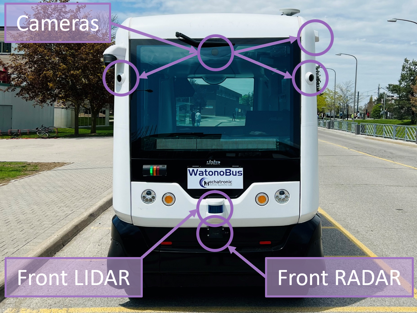
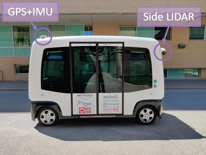
WATonoBus is equipped with sensors in a configuration as shown in Fig. 1 so that it can sense all surrounding objects. The following subsections will present the work in details.
II-A Sensors and Configuration
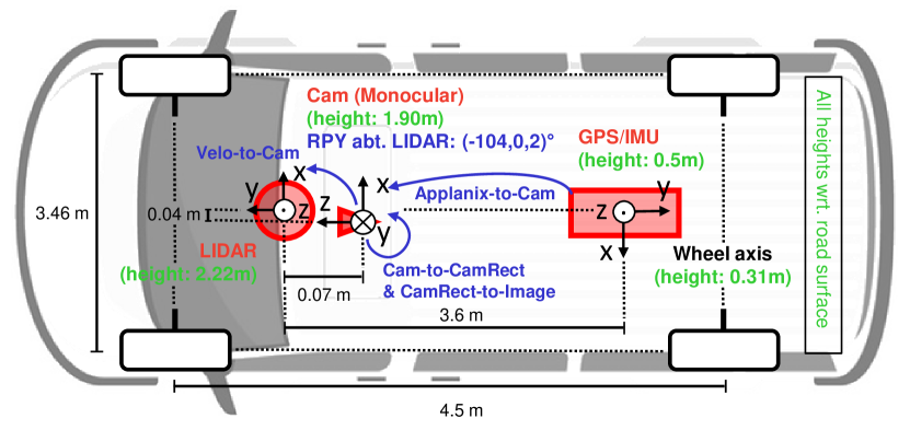
The WATonoBus is instrumented with several 3.2MP Basler Ace cameras, a combination of 32 channel Robosense LiDARs, an Applanix POS LVX GNSS, and 2 Continental ARS408-21 Radars to adequately detect any obstacles in its vicinity. The sensor dimensions, mounting positions, reference frames, and transforms are shown in Fig. 2.
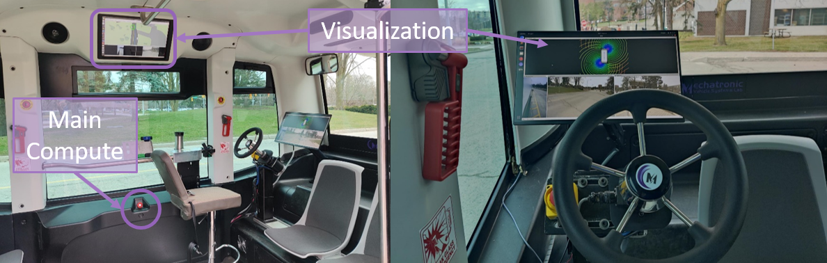
Moreover, the compute system consists of an NVIDIA Jetson Orin AGX embedded unit along with visualization and utility modules on an Intel NUC Ruby with information flow via the Robot Operating System (ROS) [25].
II-B Sensor Calibration
To perform LiDAR-camera calibration, To calibrate LiDAR and camera, we establish a six-degree-of-freedom extrinsic transform. Initially, LiDAR points are projected onto the image plane with a preliminary guess. Refinement is achieved through manual or algorithmic adjustments using projection error, identifiable qualitatively in the image or quantitatively via checkerboard corner positions. This method eliminates the need for specialized calibration boards. Calibration was successfully performed using a developed tool, available here.111https://github.com/Neel1302/LiDAR-camera-calibration.
Calibrating multiple LiDARs is crucial for maintaining a consistent and accurate representation of the environment, aligning data from different LiDARs despite variations in their installation positions and orientations. The Iterative Closest Point (ICP) algorithm is commonly employed for this task [26]. ICP iteratively minimizes differences between point clouds by identifying corresponding points, estimating a transformation matrix for optimal alignment, and repeating this process until a predefined criterion is met. The resulting transformation matrix provides the relative pose between the LiDARs, allowing for accurate 3D perception by bringing all point cloud data into a common coordinate system during operation.
Compensating for ego vehicle motion in LiDAR data processing is crucial to address distortions introduced by the vehicle’s movement during the LiDAR sampling period. For instance, in a system with three LiDARs operating at 10Hz, where each sample takes about 100ms, ego motion can lead to inaccuracies. To mitigate this, a motion compensation method is proposed, leveraging high-frequency Inertial Navigation System (INS) data. INS provides continuous position and orientation information at a higher frequency than LiDARs, enabling real-time correction of LiDAR data. Each point in the point cloud is timestamped, allowing the determination of the LiDAR sensor’s precise pose at the moment of each point’s sampling using INS data. Motion compensation involves establishing the transformation between the recorded pose and the pose at the end of the sampling period. This transformation, applied within 5ms, corrects for ego motion, enhancing the accuracy of the point cloud representation and improving subsequent data analysis and processing tasks.
III WATonoBus Software System
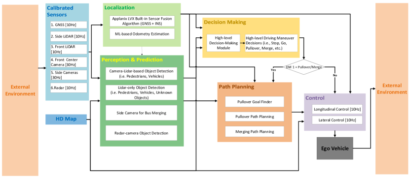
In this section, we propose a multi-modal and modular software architecture with considerations for adverse weather conditions. The high-level system diagram is shown in 3. The following subsections will present each functional module in details.
III-A Perception
Equipped with sensors like cameras, LiDARs, and radars, the bus is adept at navigating in diverse weather conditions. These sensors ensure robust sensing capabilities for the perception module, even in challenging scenarios such as snowy weather.
III-A1 2D Camera Detection
YOLO (You Only Look Once) v4 stands out as a real-time object detector, showcasing a notable advancement in the YOLO detector series by achieving enhanced accuracy and speed compared to its predecessors [27]. In addition, YOLOv4 adheres to the end-to-end object detection philosophy. This means the model is trained to predict class probabilities and bounding box coordinates directly from full images within one evaluation, distinguishing it from methods involving separate steps for region proposal and classification. The architecture of YOLOv4 compromises three key components: the backbone (CSPDarknet53), the neck (PANet and SAM block), and the head (YOLOv3 head). These components efficiently extract and fuse features, contributing to the model’s performance. Furthermore, YOLOv4 employs various state-of-the-art techniques such as Mish activation, CIOU loss, and DropBlock regularization, alongside features such as multiple anchor boxes per grid cell and three scales for detection. Recognizing these attributes, we developed a ROS package based on YOVOv4 and retrained the network with domain-specific data for our campus environment.
III-A2 LiDAR-only Detection
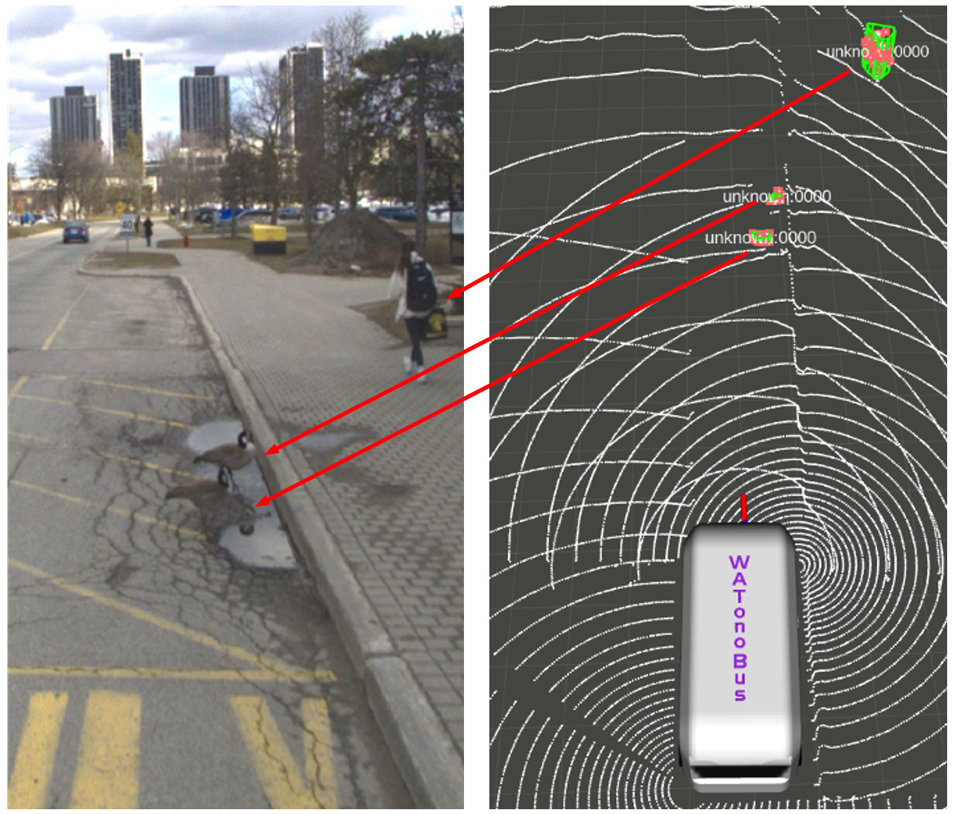
LiDAR-only detection provides a reliable and accurate enhancement to camera-based detection, particularly for uncommon object and curb detection under adverse weather conditions. It begins with the pointcloud concatenation from the front and two side blind-spot LiDAR sensors. Firstly, an adaptive grid ground segmentation algorithm is employed to remove ground points. Leveraging HD map information, it divides the combined point cloud into multiple regions, allowing for a more accurate and robust estimation of road surfaces. This is achieved by adjusting road surface fitting thresholds based on distances to the ego vehicle, employing stricter thresholds for closer areas and more lenient thresholds for regions further away. This approach effectively enhances the model’s robustness against noises generated by ego vehicle motion or erroneous point cloud reflections, ensuring the detection of all points above the road surface for subsequent object detection. After ground segmentation, an adaptive noise point detection filters out potential points from raindrops or snowflakes. Density-Based Spatial Clustering of Applications with Noise (DBSCAN) algorithm is employed for object clustering [28], enhancing LiDAR-based detection’s robustness in identifying unfamiliar objects. One example for goose detection is shown in Fig. 4. The algorithm identifies obstacle points, selects candidate points close to the ground, and incorporates additional data points in the absence of LiDAR information. For varying curb shapes, a lateral residual model is used. For safety, candidate points on the left of the fitted curb model are reassigned as obstacles, aiding in detecting objects like geese near the curb.
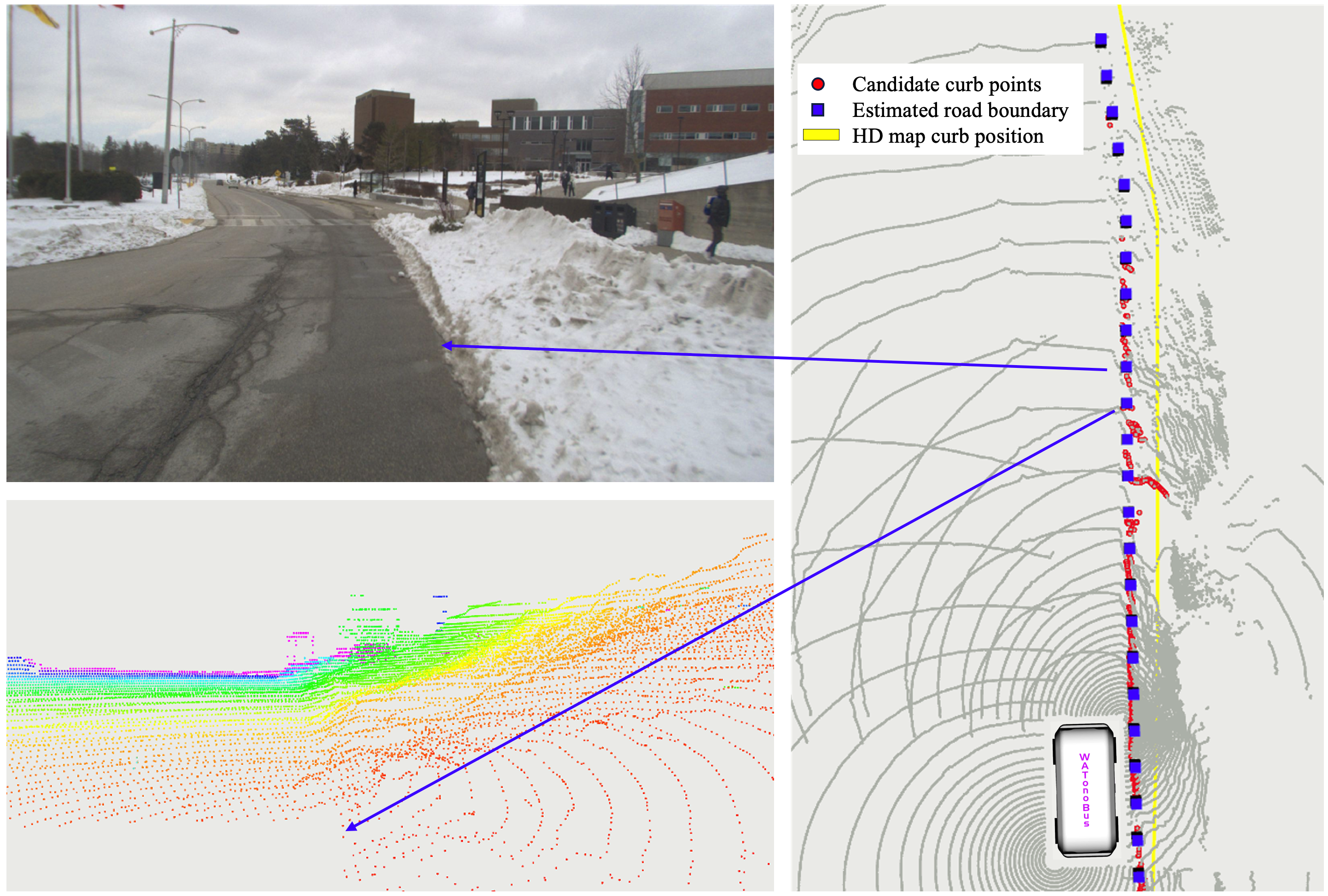
In addition to uncommon object detection, LiDAR-only detection can perceive snow-covered curbs by employing HD maps to partition potential curb points in the point cloud into adjacent road regions. This segmentation provides accurate driving boundary constraints even when actual boundaries and HD maps misalign due to positioning errors or snow obscuration. In challenging scenarios, where snow invades road regions and blurs road boundaries, a weight is introduced during road surface model fitting to mitigate errors. Fig. 5 exemplifies our approach’s effectiveness in curb detection after heavy snow, showcasing a comparison between camera view and point cloud, and revealing actual drivable space detection result in challenging conditions.
III-A3 Radar-only Detection
Radar-only detection offer another level of robustness in WATonoBus perception module since it can operate efficiently under various weather conditions, especially in poor visibility conditions. In addition, the wide filed of view and long-range capabilities (up to 250m) of the selected radar sensors enable anticipatory driving, allowing autonomous vehicles to adjust speed or change lanes in response to upcoming traffic situations. Besides, radar also possesses inherent advantages to distinguish between stationary and moving objects. A customized tracking algorithm is implemented for the selected radar sensors to estimate both longitudinal and lateral velocities of the detected objects. Specifically, longitudinal velocity is essentially the rate of change of distance in the direction of the radar’s line of sight, while lateral velocity refers to the rate of change of distance perpendicular to the radar’s line of sight. Moreover, the objects’ paths can be predicted correspondingly, thus allowing for proactive responses from WATonoBus. These strengths of radar-only detection can complements other sensing modalities, facilitating reliable navigation and safety.
In addition to tracking and prediction, the Radar Cross Section (RCS) of radar-detected objects can be useful in object classification. RCS is a measure of how detectable an object is with a radar. It’s influenced by factors like the size, material, and shape of the object, as well as the radar’s incidence angle. An object with a larger RCS is likely to be a larger vehicle, like a truck or a bus, while an object with smaller RCS might be a motorcycle or a pedestrian. This information can be useful for classifying different objects, thereby enabling ego vehicle to make safer decisions.
III-A4 Fusion
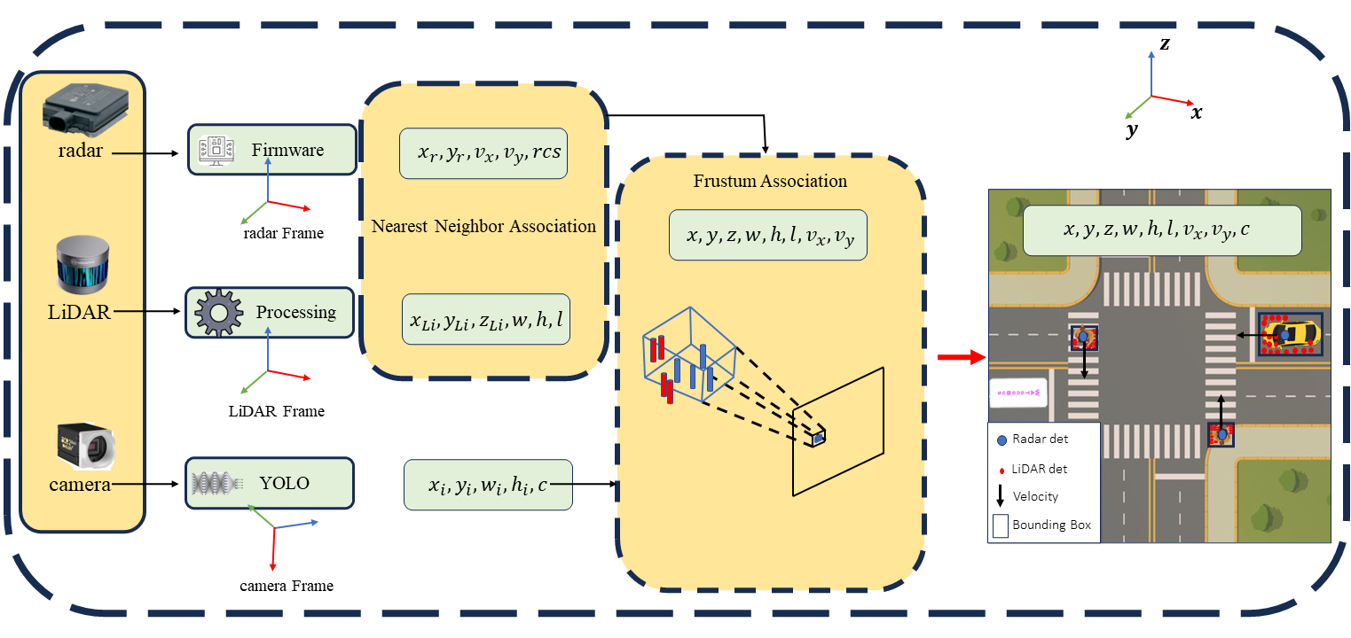
An object detection and tracking fusion algorithm is employed in WATonoBus to leverage the strengths of camera, LiDAR, and radar, combining their outputs for a more robust and accurate representation of the surrounding environment. Particularly, we employ a late fusion strategy, where each sensor’s data is processed independently before being combined (See Fig. 6). The first step involves associating the radar and LiDAR detection results. The radar-only detection algorithm estimates longitudinal and lateral velocities and RCS of detected objects, while the LiDAR-only detection algorithm generates a point cloud to indicate the shape and distance of these objects. After that, we project the combined radar and LiDAR information into the image space used by the camera-only detection algorithm. This aligns the object detection results with camera’s depth priors, providing a coherent view of the objects in the environment in relation to the imagery captured. Following the frustum approach, the fusion is carried out based on the depth order. This ensures a more accurate and holistic representation of the detected objects in the 3D space, considering the depth information from the camera and the associated data from radar and LiDAR. The final output of the fusion algorithm is a comprehensive three-dimensional bounding box encapsulating each detected object, along with its estimated velocities.
This late fusion approach allows us to fully leverage the strengths of each sensor, resulting in a more accurate and reliable object detection and tracking system. The radar fusion with LiDAR point cloud in the first step will enable the scheme to eliminate the false alarms both for radar and LiDAR in challenging weather conditions. Therefore, if the LiDAR-radar fused detections did not find a association with a camera bounding box, it will be labeled as an unknown object. This result combines the best of all sensor capabilities and offers a detailed understanding of each object’s position, dimensions, and motion, enabling the shuttle to make well-informed navigation decisions, thereby significantly enhancing the safety and reliability of WATonoBus.
III-B Localization
WATonoBus requires precise positioning to safely navigate through the drivable space in different weather conditions. This involves accessing the vehicle’s current location and heading while taking into account the location of road boundaries and nearby landmarks through High Definition (HD) maps. Accordingly, a dependable localization module is designed with both GNSS-based and GNSS-denied capabilities.
III-B1 GNSS-Based Capability
WATonoBus is equipped with an Applanix POS LVX GNSS-Inertial system aided with Real-Time Kinematic (RTK). It provides the position with sub-decimal accuracy and precise heading information of the vehicle.
III-B2 GNSS-Denied Capability
In case of low accuracy or GNSS outage due to adverse weather conditions, the GNSS-denied capability provides a temporary localization solution for the vehicle to perform a safe stop maneuver. It fuses machine-learning-based odometry estimations with LiDAR detections of georefrenced nearby HD map landmarks such as, light poles, building planes, and road curbs to estimate the location and heading of WATonoBus. The use of detections of large nearby landmarks that stand out from the environment ensures reliable localization when the road is not visible (e.g., covered by snow).
III-B3 HD Map
To form the HD map, the entire drivable space is discretized into a finite number of equally spaced intervals along an -curve, which is a one-dimensional path coordination system that describes the vehicle’s location with a single scalar (Fig. 7). At each -coordinate, a record of different information is stored in a database that forms the HD map. When WATonoBus is operating in GNSS-denied conditions, the dependable localization module will retrieve the information of reliable landmarks associated with the current s-coordinate from the HD map database.
III-C Decision Making
The objective of decision making module is to make safe driving behavior decisions based on the information from perception, prediction, localization modules, and HD map [29]. The high-level decisions will then serve as the inputs to the downstream modules to perform path planning, pullover/merging, and vehicle control. Within the service environment of WATonoBus, the driving behavior decisions are limited to Go/Stop decisions during normal driving and intersection handling, and additional Pullover/Merge, door open/close decisions at bus stop regions. Apart from normal driving decisions, the decision making module will also output emergency stop decisions as the safety fallback strategy. Furthermore, although all the interested obstacles will be reviewed through the decision making module, the final decision will be made with respect to the highest risk obstacle. To achieve the aforementioned objective, finite state machine (FSM) was chosen as the backbone in WATonoBus decision making module (See Fig. 8) because its strengths in structure modularity, interpretation transparency, and robustness to errors or unexpected events [30].
The three important FSM components of the WATonoBus decision making module are states, state transition conditions, and decision-making logic in each state. In an FSM, a state represents a unique situation in the system. In this case, the states are defined based on the static road features in the bus service environment. Specifically, there are normal road segments, all-way stop T-shape intersections, and bus stop regions along the campus ring road. Therefore, the five major states in FSM are defined, namely normal driving, intersection handling, pullover, merging, and passenger on-boarding states. Moreover, to handle the unexpected events, an emergency state is added. A transition in the FSM is a change from one state to another. For WATonoBus decision making module, the transitions are mainly governed by the ego vehicle location and the perception results. Specifically, the ego vehicle location is used to compute the remaining distance to the coming static road features such as all-way stops or bus stop regions. For example, the FSM will change to the pullover state if the ego vehicle is approaching to a bus stop region and then a pullover path will be required. In addition, perception results contain the obstacles around the ego vehicle, indicating whether it is safe to resume bus normal driving. For instance, if there is no vehicle approaching from the rear, the FSM will switch from pullover state to merging state after waiting for passenger on-boarding. Lastly, decisions made under each state can base on different logic due to the traffic rules and vehicle control requirements. The traffic rules in each FSM state list the expected ego vehicle behaviors. To handle an intersection properly, a few traffic rules need to be satisfied in sequence. Assuming there is no pedestrian, the ego vehicle needs to first check if a stop is required for the intersection-waiting vehicle in its lane. It will then be required to stop at the intersection for a while till the intersection is clear. Depending on the arrival order, a decision of whether to yield for the waiting vehicle at other intersection entrances needs to be made. After clearing all these traffic rules check, the ego vehicle can finally start moving and let FSM switch from intersection handling to normal driving state. In addition to traffic rules, the decision-making logic in each state differ from the required vehicle control parameters. For instance, the maximum speed of merging is slower than that of normal driving to ensure the bus to carefully merge out of the bus region while be able to stop immediately for any vehicles suddenly come from the rear.
III-D Path Planning
WATonoBus relies on path planning to safely and efficiently navigate through the environment. This involves determining a path from the vehicle’s current location to its intended destination while taking into account obstacles, traffic regulations, and other factors. There are two main components to path planning, namely global and local path planning.
III-D1 Global path planning
The global planner determines a high-level path from the current vehicle location to the destination, utilizing HD map information. This algorithm ensures a safe and efficient path, considering any vehicle or environmental constraints. As WATonoBus operates on a one-lane road, the global planner defines the right curb and center line as the right and left boundaries of the drivable space. The middle of this space is assigned as the reference path for the bus.
III-D2 Local path planning
The task of local path planning is to come up with a more detailed path that follows the global path while taking into account the current state of the vehicle and any obstacles in its immediate surroundings. Moreover, this involves devising a path for the WATonoBus to safely execute pullover and merging maneuvers as needed. These are typically done using potential field [31] and Bezier curves [32, 33, 34]. With the potential field method, we have a mathematical framework to adjust the reference path of the bus whenever obstacles are detected within its drivable space. Following this, smooth segments are generated using Bezier curves from the modified waypoints obtained through the potential field method. For the pullover and merging maneuver, the waypoints are produced using the Bezier curves and some control points. By combining the potential field with Bezier curves, the WATonoBus can quickly and safely navigate through its environment and do its missions.
Following the local path, the objective of WATonoBus motion controller is to select a desired speed and steering angle for the system to track at each sampling instant that enables the vehicle to follow the reference path while safely interacting with obstacles. The longitudinal controller utilizes a feed-forward algorithm that considers the position and velocity of the ego vehicle relative to obstacles. Firstly, the position of the WATonoBus and other obstacles along the path is estimated. The distance difference between the bus and obstacles along the path is then calculated. If there are no obstacles in the vicinity of the bus, the desired velocity selected by the controller is updated incrementally at each sampling instant using
| (1) |
where is the desired velocity at the sampling instant , is the nominal desired acceleration, and is the sampling time. This relationship enables the bus to freely accelerate or decelerate towards the reference velocity of 20 km/h. The sign of depends on whether the vehicle’s velocity is above or below 20 km/h, and is held at 20 km/h once the vehicle reaches this setpoint. In the presence of obstacles, the relationship remains similar; however, the nominal acceleration is replaced by a desired acceleration that the vehicle must achieve if it is to maintain a minimum spacing of from the obstacle. In this case, the desired velocity is updated as
| (2) |
| (3) |
The lateral controller considers the vehicle’s path tracking error to select desired steering angles that enable the position of the vehicle to converge with the path [35, 36, 37]. After determining the position of the vehicle, a ”look ahead” point along the path at the position ahead of the bus is selected; the distance between and is referred to as the look ahead distance, and it is selected by considering the velocity of the vehicle. Fig. 9 displays how the the vehicle’s position and the position of the look ahead point are used to compute the vehicle’s heading error with respect to the path, .
The heading error then serves as the input to a PID controller, where the reference heading error is 0; the output of the controller is the desired steering angle . As the WATonoBus has all wheel steer functionality, serves as the desired angle for the front wheels while is the desired angle for the rear wheels.
III-E Safety Module
III-E1 Safety Testing and Validation
WATonoBus prioritizes system safety through offline validation, real-time monitoring, and continuous engineering with black-box recording for edge cases during deployments. Both software and hardware components adhere to Functional Safety and SOTIF guidelines [38]. In addition, Failure Tree Analysis (FTA) and Systems-Theoretic Process Analysis (STPA) are used to assess potential failure cases and establish safety goals for the designated operational area.
During the offline development and testing stage, we simulated the parallel virtual environment of the campus ring road to validate our software across key scenarios. Safety validation in virtual traffic minimizes the risk of discovering high-impact software deficiencies in the real world. To encompass various challenging cases, we developed a scenario generator to explore potentially dangerous movements of vehicles and pedestrians. It considers various configuration parameters like the number of traffic participants, their motion and velocity profiles. We explore different combinations of these configuration parameters in testing scenario generation and then examine the performance of decision making and control modules for any potential failures. Any collisions and rule violations in the simulation will be reported and examined for further improvements.
III-E2 Safety Monitor and E-Stop
During real-time operation, system safety is maintained through reliability monitoring and fail-safe modules. Reliability monitoring module checks location, weather, and sensor performance, generating malfunction signals within the predefined Operational Design Domain (ODD) [39]. These signals indicate the current estimation of system reliability in perception, localization, and planning. The fail-safe module responds to warnings by prompting the operator to take over or initiating an emergency stop based on warning priority. Fig. 8 illustrates that all normal states can transition to an emergency stop through a software-level trigger. In the event of software freeze, an additional hardware trigger ensures a hard emergency stop.
III-E3 Black Box Recording
Our blackbox recording module is designed to enhance system learning and ensure continuous improvement through real world edge case recordings. This module maintains a rolling log of the last 30 seconds of operation, capturing crucial data on the shuttle’s state, sensor readings, and decision-making processes. A key feature of this module is its ability to recognize when a human operator takes over the controls. Once this event is detected, this module immediately stores the preceding 30 seconds of data into a rosbag, a file format in ROS used for storing ROS message data. This captured data provides valuable insights into the circumstances that led to the operator’s intervention. Simultaneously, the module emits a beeping sound to alert the operator of the recording process and the need to provide feedback. This is a crucial step in our process, as the operator is then given 30 seconds to provide a verbal summary of the situation that prompted the takeover. This feedback serves as a first-hand account of the event, aiding in our understanding of any gaps in the system’s autonomous decision-making capabilities and allowing us to refine and improve our technology further.
IV Learning from Daily Operation
This section presents the handling procedure and lessons learned from both regular bus service and severe weather encountered in WATonoBus daily operations, followed by discussing the insights gained from these case studies.
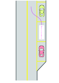
IV-A Bus Stop Handling
The bus stop handling task involves four functional modules: dynamic spot identification, passenger on/off boarding, merging handling, and pullover/merging path planning modules (See Fig. 10). The dynamic pullover spot identification module is crucial for ensuring safe and precise stopping at bus stops. Triggered by the decision-making (DM) module when the shuttle approaches a bus stop, this module conducts a careful scan of the area within a longitudinal distance of up to 20 meters from the shuttle’s current position. It checks for any obstacles, such as stationary vehicles, pedestrians, or bollards, that may obstruct the shuttle’s path during pullover. The module generates a specific point indicating a safe pullover spot, which is then relayed to the DM module and further to the path planner and control modules for navigation to the designated spot.
The passenger on/off boarding module ensures a comfortable bus service experience. After pullover at the bus stop, the shuttle automatically opens the door and uses the in-door sensor to detect potential passengers attempting to board or alight. After a continuous check and waiting for a sufficient time, the shuttle locks the door and transitions to the merging status.
The merging handling module combines rear radar and camera results for a comprehensive view of the traffic behind the ego vehicle, improving hazard detection and reaction capabilities. The radar provides reliable long-range detection, crucial for monitoring approaching traffic. It not only detects vehicles but also estimates their velocities, aiding in understanding their movement patterns. The rear camera complements these capabilities, serving as the final vote to prevent radar false alarms during merging. This fused data informs the vehicle’s DM process, calculating the optimal timing and speed for a smooth merge into traffic. Anticipating potential conflicts by considering the speed and trajectory of approaching vehicles, our system adjusts its strategy for safety, ensuring the well-being of shuttle bus passengers and other road users.
The pullover/merging path planning module ensures a smooth path for the ego vehicle during pullover at bus stops or merging maneuvers. Specific waypoints are crucial during pullover, determined considering the bus’s current position, heading, and the identified parking location. Bezier curves are utilized to create a smooth path between these waypoints. Similarly, for merging, waypoints are determined based on the bus’s starting position, orientation, and the target location along its reference path. These waypoints guide the creation of a smooth path using Bezier curves.


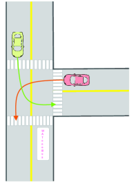
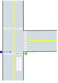
IV-B Intersection Handling
Non-signalized intersections pose challenges due to dynamic traffic flow, right-of-way determination, and potential conflicts (See Fig. 11). Unlike signalized intersections, they lack explicit instructions, demanding advanced perception, DM, and control capabilities for autonomous shuttle buses. Non-signalized intersections rely on right-of-way rules, which can be influenced by factors such as vehicle priority, the order of arrival. Our WATonoBus records the order of arrival for vehicle actors to decide the road priority. When comparing with pedestrian and cyclist at crossings, the shuttle consider itself lowest road priority. Moreover, non-signalized intersections introduce the possibility of conflicts arising from simultaneous movements of different road users. Conflicts can occur due to misjudgment of gaps, ambiguous driver intentions, or violations of right-of-way. The autonomous shuttle bus must be equipped with robust perception systems and prediction modules to detect and track vehicles, pedestrians, and cyclists. To reach as safe and robust behavioral planning for the autonomous driving shuttle bus, we use event-driven technique that react the most potential conflict that guarantee the vehicle is always at safe states.
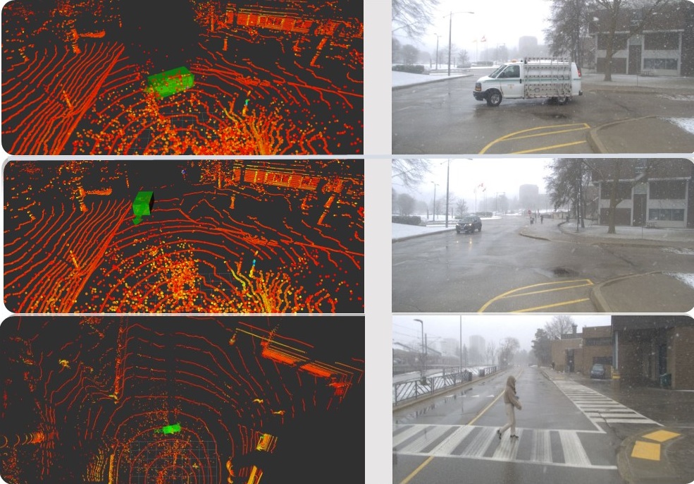
IV-C Perception Performance under Snow
In autonomous vehicle systems, reliable object detection under adverse weather conditions remains a complex and critical challenge. Our WATonoBus perception system overcomes this challenge through the fusion of radar, LiDAR, and camera data, particularly in snowy settings. This integrated approach successfully detects objects in three disparate yet commonplace road scenarios: a van entering the roadway, a car in the opposite lane, and a pedestrian crossing a street, as shown in Fig. 12. For detecting a van entering the road, the radar’s capacity to measure distance and speed plays a crucial role, especially when fused with the camera’s high-definition imaging. The camera contributes valuable details like color and texture, allowing for a highly integrated and predictive object detection framework. This multi-sensory combination anticipates the van’s potential actions, enabling dynamic adjustments for safer autonomous navigation. In the case of a car in the opposite lane, snowy conditions can introduce additional complexities like fog, glare, and reduced contrast. Here, radar’s strong penetration capabilities prove indispensable for initial object detection and range estimation. Combined with the LiDAR’s noisy but detailed spatial data and the camera’s visual cues, the system doesn’t just detect the car; it precisely locates and tracks it, adding another layer of reliability and safety in treacherous weather conditions. Regarding a pedestrian on a crosswalk, snowy conditions often introduce noise into the LiDAR point clouds, making it more challenging to distinguish the shape and position of a pedestrian. In this setting, radar’s Doppler velocity data becomes invaluable. Radar’s robustness to weather interference complements the high-resolution LiDAR data, filtering the noise and ensuring a reliable and comprehensive multi-modal perception of the pedestrian. This fusion mitigates the limitations posed by snowy conditions, providing an enhanced layer of safety and accuracy.
IV-D Learning and Discussion
The learning from the WATonoBus operational scenarios highlights the robustness and adaptability in addressing complex bus service tasks and adverse weather conditions. The pullover spot identification and merging handling modules showcase the system’s capability to navigate intricate tasks, ensuring safe and precise operations at bus stops. The integration of passenger on/off boarding mechanisms not only enhances user experience but also prioritizes safety, demonstrating a holistic approach to autonomous bus service. Moreover, the intelligent decision-making at non-signalized intersections reflects WATonoBus can dynamically determine right-of-way in complex traffic scenarios. The perceptual performance under snow adds another layer of strength to the WATonoBus design. The successful fusion of radar, LiDAR, and camera data in challenging weather conditions exemplifies the system’s reliance on multi-sensory inputs. Understanding the distinct role of each sensor in different scenarios emphasizes the system’s adaptability, ensuring reliable object detection and tracking under adverse weather. In essence, WATonoBus stands out as a resilient and intelligent autonomous bus service, capable of handling complex tasks with precision and adapting seamlessly to adverse weather conditions. The integration of advanced modules, coupled with a multi-sensory perception system, positions WATonoBus as a robust solution for safe and reliable autonomous transportation services.
Acknowledgment
The authors would like to acknowledge the financial support of Natural Sciences and Engineering Research Council of Canada (NSERC) and Canadian Foundation for Innovation (CFI) in this work.
V Conclusion
This paper introduces the WATonoBus project, addressing foundational research questions and design concepts with real-world experimental validation. The aim is to contribute to the continuous advancement of autonomous driving technology, providing essential insights into its feasibility, societal acceptance, and economic viability through collaborative testing and piloting. Our modular software architecture ensures all-weather functionality, specifically addressing adverse weather conditions such as rain, snow, and fog. This approach has been experimentally validated in challenging real-world scenarios. The perception module utilizes multi-modal sensor fusion for accurate object and drivable road boundary detection under adverse weather conditions, enhancing safety and reliability. The localization module demonstrates GNSS-denied capabilities, particularly crucial in challenging weather conditions. The decision-making module, supported by a dedicated safety module, ensures robust and safe autonomous operation. The intelligent bus stop pullover/merging function is tailored for shuttle bus service, adding efficiency to the shuttle’s operations. Valuable insights derived from edge case learning during daily shuttle bus operations contribute to the project’s continuous improvement. The construction of the distinct vehicle prototype and over a year of service experience culminate in a public unveiling, showcasing significant advancements and practical implementations in the autonomous driving domain.
References
- [1] A. Bucchiarone, S. Battisti, A. Marconi, R. Maldacea, and D. C. Ponce, “Autonomous shuttle-as-a-service (asaas): Challenges, opportunities, and social implications,” IEEE Transactions on Intelligent Transportation Systems, vol. 22, no. 6, pp. 3790–3799, 2020.
- [2] C. Sun, S. Li, D. Cao, F.-Y. Wang, and A. Khajepour, “Tabular learning-based traffic event prediction for intelligent social transportation system,” IEEE Transactions on Computational Social Systems, vol. 10, no. 3, pp. 1199–1210, 2023.
- [3] J. Cregger, M. Dawes, S. Fischer, C. Lowenthal, E. Machek, and D. Perlman, “Low-speed automated shuttles: State of the practice final report,” 2018.
- [4] C. Sun, C. Wang, Z. Deng, and D. Cao, “Dimensionless model-based system tracking via augmented kalman filter for multiscale unmanned ground vehicles,” IEEE/ASME Transactions on Mechatronics, vol. 26, no. 2, pp. 600–610, 2021.
- [5] K. Hilgarter and P. Granig, “Public perception of autonomous vehicles: A qualitative study based on interviews after riding an autonomous shuttle,” Transportation research part F: traffic psychology and behaviour, vol. 72, pp. 226–243, 2020.
- [6] I. 22737:2021, “Intelligent transport systems – low-speed automated driving (lsad) systems for predefined routes – performance requirements, system requirements and performance test procedures,” 2021.
- [7] “Parkshuttle, available online: https://www.2getthere.eu/systems/autonomous-shuttles/, Accessed: 2023-08-15.”
- [8] C. Iclodean, N. Cordos, and B. O. Varga, “Autonomous shuttle bus for public transportation: A review,” Energies, vol. 13, no. 11, p. 2917, 2020.
- [9] M. Azad, N. Hoseinzadeh, C. Brakewood, C. R. Cherry, and L. D. Han, “Fully autonomous buses: A literature review and future research directions,” Journal of Advanced Transportation, vol. 2019, pp. 1–16, 2019.
- [10] C. Goldbach, J. Sickmann, T. Pitz, and T. Zimasa, “Towards autonomous public transportation: Attitudes and intentions of the local population,” Transportation Research Interdisciplinary Perspectives, vol. 13, p. 100504, 2022.
- [11] J. W. Van der Wiel, “Automated shuttles on public roads: Lessons learned,” in ITS European Congress, 2017.
- [12] H. P. Kristin Kolodge, Sarah Ciotte, “Mcity driverless shuttle: What we learned about consumer acceptance of automated vehicles mcity driverless shuttle: What we learned about consumer acceptance of automated vehicles,” 2020.
- [13] K. Mouratidis and V. Cobeña Serrano, “Autonomous buses: Intentions to use, passenger experiences, and suggestions for improvement,” Transportation Research Part F: Traffic Psychology and Behaviour, vol. 76, pp. 321–335, 2021. [Online]. Available: https://www.sciencedirect.com/science/article/pii/S1369847820305921
- [14] I. Roche-Cerasi, “Public acceptance of driverless shuttles in norway,” Transportation research part F: traffic psychology and behaviour, vol. 66, pp. 162–183, 2019.
- [15] A. O. Salonen and N. Haavisto, “Towards autonomous transportation. passengers’ experiences, perceptions and feelings in a driverless shuttle bus in finland,” Sustainability, vol. 11, no. 3, p. 588, 2019.
- [16] M. Feys, E. Rombaut, and L. Vanhaverbeke, “Experience and acceptance of autonomous shuttles in the brussels capital region,” Sustainability, vol. 12, no. 20, p. 8403, 2020.
- [17] P. Launonen, A. O. Salonen, and H. Liimatainen, “Icy roads and urban environments. passenger experiences in autonomous vehicles in finland,” Transportation research part F: traffic psychology and behaviour, vol. 80, pp. 34–48, 2021.
- [18] M. M. Nesheli, L. Li, M. Palm, and A. Shalaby, “Driverless shuttle pilots: Lessons for automated transit technology deployment,” Case studies on transport policy, vol. 9, no. 2, pp. 723–742, 2021.
- [19] L. Eckstein and S. Pischinger, Eds., 30. Aachen Colloquium Sustainable Mobility: October 4th-6th, 2021, Aachen, 1: October 5th, 2021, XI, 948 Seiten : Illustrationen, Diagramme. - 2: October 6th, 2021, XI Seiten, Seite 949-2012 ; Illustrationen, Diagramme; 1st edition, 30. Aachen Colloquium Sustainable Mobility, Aachen (Germany), 4 Oct 2021 - 6 Oct 2021. Aachen: Institute for Automotive Engineering, RWTH Aachen University, Oct 2021. [Online]. Available: https://publications.rwth-aachen.de/record/835327
- [20] M. Henning, J. Müller, F. Gies, M. Buchholz, and K. Dietmayer, “Situation-aware environment perception using a multi-layer attention map,” IEEE Transactions on Intelligent Vehicles, vol. 8, no. 1, pp. 481–491, 2023.
- [21] T. Stolte, S. Ackermann, R. Graubohm, I. Jatzkowski, B. Klamann, H. Winner, and M. Maurer, “Taxonomy to unify fault tolerance regimes for automotive systems: Defining fail-operational, fail-degraded, and fail-safe,” IEEE Transactions on Intelligent Vehicles, vol. 7, no. 2, pp. 251–262, 2022.
- [22] M. Horn, T. Wodtko, M. Buchholz, and K. Dietmayer, “Online extrinsic calibration based on per-sensor ego-motion using dual quaternions,” IEEE Robotics and Automation Letters, vol. 6, no. 2, pp. 982–989, 2021.
- [23] M. Henning, M. Buchholz, and K. Dietmayer, “Situation-aware environment perception for decentralized automation architectures,” in 2022 IEEE Intelligent Vehicles Symposium (IV), 2022, pp. 1087–1092.
- [24] A. Kampmann, M. Lüer, S. Kowalewski, and B. Alrifaee, “Optimization-based resource allocation for an automotive service-oriented software architecture,” in 2022 IEEE Intelligent Vehicles Symposium (IV), 2022, pp. 678–687.
- [25] Stanford Artificial Intelligence Laboratory et al., “Robotic operating system.” [Online]. Available: https://www.ros.org
- [26] Z. Zhang, “Iterative point matching for registration of free-form curves and surfaces,” International journal of computer vision, vol. 13, no. 2, pp. 119–152, 1994.
- [27] A. Bochkovskiy, C.-Y. Wang, and H.-Y. M. Liao, “Yolov4: Optimal speed and accuracy of object detection,” ArXiv, vol. abs/2004.10934, 2020.
- [28] M. Ester, H.-P. Kriegel, J. Sander, and X. Xu, “A density-based algorithm for discovering clusters in large spatial databases with noise,” in Proceedings of the Second International Conference on Knowledge Discovery and Data Mining, ser. KDD’96. AAAI Press, 1996, p. 226–231.
- [29] Y. Ma, C. Sun, J. Chen, D. Cao, and L. Xiong, “Verification and validation methods for decision-making and planning of automated vehicles: A review,” IEEE Transactions on Intelligent Vehicles, vol. 7, no. 3, pp. 480–498, 2022.
- [30] M. Jaswanth, N. K. Narayana, S. Rahul, and M. Supriya, “Autonomous car controller using behaviour planning based on finite state machine,” in 2022 6th International Conference on Trends in Electronics and Informatics (ICOEI). IEEE, 2022, pp. 296–302.
- [31] Y. Rasekhipour, A. Khajepour, S. K. Chen, and B. Litkouhi, “A potential field-based model predictive path-planning controller for autonomous road vehicles,” IEEE Transactions on Intelligent Transportation Systems, vol. 18, 2017.
- [32] J. W. Choi, R. Curry, and G. Elkaim, “Path planning based on bézier curve for autonomous ground vehicles,” 2008.
- [33] L. Han, H. Yashiro, H. T. N. Nejad, Q. H. Do, and S. Mita, “Bézier curve based path planning for autonomous vehicle in urban environment,” 2010.
- [34] X. A. Han, Y. C. Ma, and X. L. Huang, “A novel generalization of bézier curve and surface,” Journal of Computational and Applied Mathematics, vol. 217, 2008.
- [35] M. Samuel, M. Hussein, and M. B. Mohamad, “A review of some pure-pursuit based path tracking techniques for control of autonomous vehicle,” International Journal of Computer Applications, vol. 135, no. 1, pp. 35–38, 2016.
- [36] M.-W. Park, S.-W. Lee, and W.-Y. Han, “Development of lateral control system for autonomous vehicle based on adaptive pure pursuit algorithm,” in 2014 14th international conference on control, automation and systems (ICCAS 2014). IEEE, 2014, pp. 1443–1447.
- [37] J. Ahn, S. Shin, M. Kim, and J. Park, “Accurate path tracking by adjusting look-ahead point in pure pursuit method,” International journal of automotive technology, vol. 22, pp. 119–129, 2021.
- [38] ISO 21448:2022, “Road vehicles — safety of the intended functionality,” International Organization for Standardization, Geneva, CH, Tech. Rep., 2022. [Online]. Available: https://www.iso.org/standard/77490.html
- [39] C. Sun, Z. Deng, W. Chu, S. Li, and D. Cao, “Acclimatizing the operational design domain for autonomous driving systems,” IEEE Intelligent Transportation Systems Magazine, vol. 14, no. 2, pp. 10–24, 2022.
![[Uncaptioned image]](/html/2312.00938/assets/figures/bio_photos/Neel_Bhatt_v2.jpg) |
Neel P. Bhatt is currently pursuing his PhD degree in the Department of Mechanical and Mechatronics Engineering at University of Waterloo. Neel received his BASc. in Mechanical Engineering with a minor in Robotics from University of Toronto. Neel conducts research in perception, prediction, and safe autonomous decision making for autonomous vehicles. He is currently investigating methods to improve performance of real-time object trajectory prediction algorithms and interaction aware motion forecasting models for various non sign controlled urban driving settings via his work on the WATonoBus autonomous shuttle project. |
![[Uncaptioned image]](/html/2312.00938/assets/figures/bio_photos/RuiheZhang.jpg) |
Ruihe Zhang received the B.S. degree in mechanical engineering from University of Toronto, Toronto, ON, Canada, in 2019, the M.A.Sc. degree in mechanical and mechatronics engineering from University of Waterloo, Waterloo, ON, Canada, in 2021. He is currently pursuing the Ph.D. degree in mechanical and mechatronics engineering with University of Waterloo, Waterloo, ON, Canada. He is a member of the Mechatronic Vehicle Systems Laboratory (MVSL), University of Waterloo, and supervised by Prof. Amir Khajepour and Prof. Krzysztof Czarnecki. His research interests include uncertainty-aware decision-making in autonomous driving, uncertainty quantification of learning-based algorithms, and health monitoring of autonomous driving applications. |
![[Uncaptioned image]](/html/2312.00938/assets/figures/bio_photos/MinghaoNing_photo.jpg) |
Minghao Ning received the B.S. degree in vehicle engineering from the Beijing Institute of Technology, Beijing, China, in 2020. He is currently pursuing the Ph.D. degree with the Department of Mechanical and Mechatronics Engineering, University of Waterloo. His research interests include autonomous driving, LiDAR perception, planning and control. |
![[Uncaptioned image]](/html/2312.00938/assets/figures/bio_photos/Ahmad.png) |
Ahmad Reza Alghooneh is a Ph.D. candidate at the University of Waterloo. He received his master’s degree from the University of Tehran, Iran, where he focused on using deep learning to solve perception and object manipulation challenges for humanoid robots. During his master’s, he played a key role in developing the renowned Iranian humanoid robot, SURENA IV. In Canada, Ahmad collaborated closely with General Motors through the Mechatronics Vehicles System laboratory, resulting in a U.S. Patent with the company. His research focuses on sensor fusion, autonomous vehicle perception, and controls. He excels in radar-camera data fusion to address perception challenges in adverse weather conditions. |
![[Uncaptioned image]](/html/2312.00938/assets/figures/bio_photos/csun-min.jpg) |
Chen Sun received his PhD in Mechanical and Mechatronics Engineering from University of Waterloo in 2022; and the M.A.Sc degree in Electrical & Computer Engineering from University of Toronto, ON, Canada in 2017; and B.Eng. degree in automation from the University of Electronic Science and Technology of China, Chengdu, China, in 2014. He is currently a postdoctoral fellow researcher in Mechatronic Vehicle Systems Laboratory (MVSL) at University of Waterloo working on autonomous driving and safe AI related research. His research interests include autonomous driving, safety validation for cyber-physical systems, safe behavior planning and control for robots. |
![[Uncaptioned image]](/html/2312.00938/assets/figures/bio_photos/Pouya_Panahandeh.png) |
Pouya Panahandeh is currently pursuing his Ph.D. degree in the Department of Mechanical and Mechatronics Engineering at the University of Waterloo. His primary area of research interest is motion planning, prediction, and the development of safe autonomous driving systems. Specifically, he is exploring techniques to enhance the efficiency of real-time motion planning algorithms in diverse urban traffic situations. Pouya’s investigations are part of the ongoing WATonoBus autonomous shuttle project, which aims to improve the accuracy and reliability of autonomous driving in dynamic environments. |
![[Uncaptioned image]](/html/2312.00938/assets/figures/bio_photos/EhsanMohammadbagher.jpg) |
Ehsan Mohammadbagher received his B.Sc. and M.Sc. in Mechanical Engineering from Sharif University of Technology, Iran. He is currently a Ph.D. candidate at the Department of Mechatronics Engineering, University of Waterloo. He is exploring autonomous navigation, localization based on High Definition maps, vehicle state estimation and controls. |
![[Uncaptioned image]](/html/2312.00938/assets/figures/bio_photos/ted-ecclestone.jpeg) |
Ted Ecclestone recently completed his MASc degree with the Department of Mechanical and Mechatronics Engineering at the University of Waterloo, where he conducted research related to vehicle motion control for ADAS and autonomous driving applications. Prior to this, Ted obtained a BASc in Engineering Physics with a specialization in Mechanical Engineering at Queen’s University. He is currently working as a Controls Engineering Specialist on robotic automotive technology with Electrans Technologies Ltd. |
![[Uncaptioned image]](/html/2312.00938/assets/figures/bio_photos/b_maccallum.jpg) |
Ben MacCallum recently completed his MASc degree in Mechanical and Mechatronics Engineering at the University of Waterloo, with a focus in automated vehicle controls and motion planning. Previously, Ben completed his BSc in Sustainable Design Engineering at the University of Prince Edward Island. He is currently developing ADAS controls software as a Control Systems Engineer at General Motors. |
![[Uncaptioned image]](/html/2312.00938/assets/figures/bio_photos/a_khajepour.png) |
Amir Khajepour is a professor of Mechanical and Mechatronics Engineering and the Director of the Mechatronic Vehicle Systems (MVS) Lab at the University of Waterloo. He held the Tier 1 Canada Research Chair in Mechatronic Vehicle Systems from 2008 to 2022 and the Senior NSERC/General Motors Industrial Research Chair in Holistic Vehicle Control from 2017 to 2022. His work has resulted in training of over 150 PhD and MASc students, 30 patents, over 600 research papers, numerous technology transfers, and several start-up companies. He has been recognized with the Engineering Medal from Professional Engineering Ontario and is a fellow of the Engineering Institute of Canada, the American Society of Mechanical Engineering, and the Canadian Society of Mechanical Engineering. |
![[Uncaptioned image]](/html/2312.00938/assets/figures/bio_photos/e_hashemi.png) |
Ehsan Hashemi received his Ph.D. in Mechanical and Mechatronics Engineering in 2017 from University of Waterloo, ON, Canada; M.Sc. in Mechanical Engineering in 2005 from Amirkabir University of Technology (Tehran Polytechnic). He is currently an Assistant Professor at the Department of Mechanical Engineering, University of Alberta. His research interests are robotics, control theory, distributed estimation, and human–robot interaction. |