Controlled Skyrmion Ratchet in Linear Protrusion Defects
Abstract
Using atomistic simulations, we investigate the dynamical behavior of a single skyrmion interacting with an asymmetric linear protrusion array under external ac driving. When the ac drive is applied along the direction, the skyrmion moves along the hard direction of the substrate asymmetry in three phases: a pinned phase with localized skyrmion orbits, a constant velocity phase where the orbits become delocalized, and a reentrant pinned phase with larger localized orbits. We measure the dependence of the skyrmion velocity on the frequency and amplitude of the ac drive. All three phases appear for all frequency values, and in the constant velocity phase the skyrmion velocity depends only on the frequency and not on the amplitude of the ac drive. When ac driving is applied in the direction, the skyrmion moves along the easy direction of the substrate asymmetry and exhibits the same three phases as for direction driving along with a fourth phase which, at high driving frequencies, consists of a series of constant velocity phases, each with different average skyrmion velocities. For low frequencies, the constant velocity phase is lost and the skyrmion speed increases linearly with increasing ac drive amplitude due to a Magnus boost effect. Our findings suggest new ways to create reliable data transport for spintronic devices using skyrmions as information carriers, where the skyrmion direction and speed can be controlled by varying only the ac drive amplitude and frequency.
I Introduction
In the field of data storage, there is great interest in discovering novel approaches that demand lower energy consumption and offer increased data density. The rapid increase in cloud-based storage has resulted in substantial energy consumption Negru et al. (2013), a concern that can be mitigated through new data storage techniques capable of enhancing data density and data transfer efficiency. One promising direction is to employ stable topological stable objects with reduced dimensions whose transport can be controlled precisely. Recently magnetic skyrmions, which are topologically stable spin textures Nagaosa and Tokura (2013); Je et al. (2020) of size ranging from a few nanometers up to a micrometer Wang et al. (2018), have been observed experimentally in chiral ferromagnetic thin films and bulk crystals Mühlbauer et al. (2009); Yu et al. (2010); Pfleiderer et al. (2010); Münzer et al. (2010). Skyrmions are considered one of the most promising candidates for future spintronic devices Nagaosa and Tokura (2013); Everschor-Sitte et al. (2018); Fert et al. (2013) due to their reduced size and stability even at room temperatures Fert et al. (2013, 2017), as well as their ability to be transported via the application of a spin-polarized current. The current density necessary to drive a skyrmion is over five orders of magnitude smaller than that required to move magnetic domain walls Schulz et al. (2012); Jonietz et al. (2010), and as a result, skyrmion-based devices could provide more reliable and energy-efficient high density data storage. Some of the proposed skyrmion-based devices include magnetic logic gates Luo and You (2021); Shu et al. (2022); Zhang et al. (2015a), diodes Shu et al. (2022); Bellizotti Souza et al. (2022); Feng et al. (2022); Wang et al. (2020); Song et al. (2020); Jung et al. (2021); Zhao et al. (2020), and transistors Zhang et al. (2015b). Magnetic skyrmions could also be used in non-conventional computing, such as audio classification artificial intelligence Msiska et al. (2023) and neuromorphic computing Song et al. (2020); Li et al. (2017, 2021). In order to harness magnetic skyrmions effectively for spintronics devices and unconventional computing, precise control over their motion is crucial, and significant efforts have been devoted to achieve this goal Fert et al. (2013); Luo et al. (2018); Zhang et al. (2023a); Pfleiderer (2011); Wiesendanger (2016); Kang et al. (2016); Zhang et al. (2020).
Skyrmions exhibit many similarities to other overdamped particles. Both minimize their repulsive interactions by forming a triangular lattice, can be set into motion by external drives, and interact with defects in the material Olson Reichhardt et al. (2014); Reichhardt and Reichhardt (2016). A distinguishing property of skyrmions is the presence of a strong non-dissipative Magnus force, which results in a very distinct dynamical behavior since the Magnus force creates a velocity component perpendicular to the net force acting on the skyrmion. The sign of this perpendicular component depends on the skyrmion winding number or topological charge Nagaosa and Tokura (2013); Litzius et al. (2017); Iwasaki et al. (2013a); Jiang et al. (2017); Lin et al. (2013a, b); Zeissler et al. (2020). Due to the presence of the Magnus term, the skyrmion moves at what is known as the intrinsic skyrmion Hall angle Nagaosa and Tokura (2013); Litzius et al. (2017); Iwasaki et al. (2013a); Jiang et al. (2017); Lin et al. (2013a, b) with respect to an applied external drive. The intrinsic skyrmion Hall angle is an important problem for technological applications, since it can cause skyrmions to move toward the edge of the sample, leading to annihilation events that limit how far the skyrmion can travel. In order to prevent this annihilation process, a precise control of the skyrmion motion is required. There is an increased effort to find new ways to control the skyrmion motion and avoid the intrinsic skyrmion Hall angle problem. Some of the proposed methods include the use of periodic pinning Reichhardt et al. (2015a, 2018); Feilhauer et al. (2020); Vizarim et al. (2021a, 2020); Reichhardt and Reichhardt (2022), sample curvature Carvalho-Santos et al. (2021); Korniienko et al. (2020); Yershov et al. (2022), interface guided motion Vizarim et al. (2021b); Zhang et al. (2022a), ratchet effects Reichhardt et al. (2015b); Souza et al. (2021); Chen et al. (2019); Göbel and Mertig (2021), temperature and magnetic gradients Yanes et al. (2019); Zhang et al. (2018); Everschor et al. (2012); Kong and Zang (2013), skyrmion-vortex coupling using heterostructures Menezes et al. (2019); Neto and Silva (2022), skyrmion lattice compression Zhang et al. (2022b); Bellizotti Souza et al. (2023), laminar flow of skyrmions Zhang et al. (2023a), soliton motion along skyrmion chains Vizarim et al. (2022); Souza et al. (2023), and skyrmions interacting with chiral flowers Zhang et al. (2023b).
The interaction of overdamped particles with asymmetric potentials under dc or ac driving has been explored widely Wambaugh et al. (1999); Vlasko-Vlasov et al. (2013); Souza et al. (2022); Martinez et al. (2020); Reichhardt et al. (2015b); Gonzalez et al. (2007); Lu et al. (2007); Olson Reichhardt and Reichhardt (2013); Villegas et al. (2005); Yu et al. (2007). For ac driving, the system may exhibit a ratchet effect in which there is a net dc transport of the particle that is generally along the easy flow direction of the potential. One of the earliest skyrmion ratchet studies involved a quasi-one-dimensional (1D) asymmetric substrate Reichhardt et al. (2015b). For ac drives applied parallel to the substrate asymmetry direction, quantized net dc displacements of the skyrmion occurred, while a Magnus induced transverse ratchet appeared when the ac driving was perpendicular to the substrate asymmetry direction. In recent work, Souza et al. Souza et al. (2021) proposed a device where the motion of a single magnetic skyrmion interacting with an asymmetric funnel array could be precisely controlled, providing an information carrier. With this geometry, it was possible to produce ratcheting motion of the skyrmion along both the easy and hard substrate asymmetry directions; however, the motion in the hard direction had low efficiency.
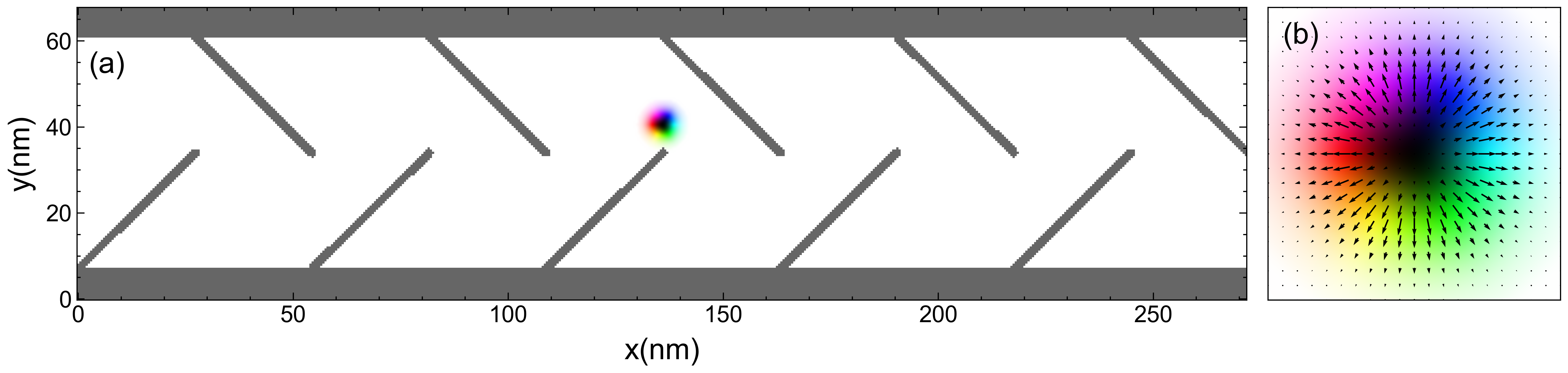
Another example of asymmetric arrays is the linear protrusion array, shown in Fig. 1, that was previously used for type II superconducting vortices by Wells Wells (2017). In that work, an external dc driving force was employed to induce a vortex diode effect. The depinning threshold was low for driving currents applied along the easy flow direction and high for driving along the hard flow direction. Wells argued that ac driving would induce a vortex ratchet effect. Here, we perform a detailed analysis of the behavior of magnetic skyrmions in a linear protrusion array, focusing on the ratchet effects that arise under ac driving with varied amplitude and frequency.
In this work we show that when the ac drive is applied along the direction, the skyrmion exhibits three dynamical phases: (i) a pinned phase (PP), (ii) a constant velocity phase (CVP) with motion along the hard substrate asymmetry direction, and (iii) a reentrant pinned phase (RPP). Within the CVP, we find that the skyrmion velocity depends exclusively on the ac driving frequency. In addition, the interval of ac drive amplitudes for which the CVP appears varies with the driving frequency. When we apply the ac drive along the direction, we uncover a more complex behavior featuring four phases: (i) PP, (ii) CVP with motion along the easy substrate asymmetry direction, (iii) RPP, and (iv) a mixture of CVP and a linear increase of the skyrmion velocity with increasing ac amplitude. Each phase appears within a well-defined range of ac amplitude and frequency. The velocity characteristics in the CVP state mirror those observed for ac driving along the direction, with the velocity being determined exclusively by the ac frequency. In the fourth phase, a succession of CVPs with distinct average skyrmion velocities emerges at higher ac drive frequencies, while for lower frequencies, the CVP dissipates and the skyrmion velocity increases linearly with the ac drive amplitude. A precise control of the skyrmion motion can be achieved by tailoring the ranges of ac amplitude and frequency in order to guide the skyrmion in a desired fashion.
II Simulation
The sample considered here is an ultrathin nanotrack of ferromagnetic material that can host Néel skyrmions. The nanotrack has dimensions of 272 nm 64 nm and a magnetic field is applied perpendicular to the film surface at K. Periodic boundary conditions are applied only along the direction. The sample contains magnetic walls close to the sample edge and a linear protrusion array of defects, where the magnetic moments that compose the walls and the linear protrusion array have very strong perpendicular magnetic anisotropy (PMA). We introduce the walls in order to confine the skyrmions along the nanotrack. Throughout this work we always consider the dynamics of a single skyrmion, and the initial skyrmion configuration is illustrated in Fig 1.
We use an atomistic model Evans (2018) for the simulations to investigate the skyrmion spin textures in detail. The Hamiltonian governing the spin dynamics is given by Iwasaki et al. (2013a, b); Seki and Mochizuki (2016):
| (1) |
The first term on the right side is the exchange interaction between the nearest neighbors that compose the set . The underlying lattice is a square spin lattice with lattice constant and exchange constant between spins and . The second term is the interfacial Dzyaloshinskii–Moriya interaction, where is the Dzyaloshinskii-Moriya vector between spins and . The third term is the spin interaction with an external applied magnetic field known as the Zeeman interaction, where is the magnetic moment magnitude and T-1s-1 is the electron gyromagnetic ratio. The last term is the sample easy-axis anisotropy, where is the anisotropy strength. We model the set of spins that compose the linear protrusion array of defects as fixed magnetic moments, , and we note that if we replace these fixed moments by defects with very strong PMA values , such as , we obtain the same result that the motion of skyrmions through the defects is prevented Zhang et al. (2022c).
The time evolution for the magnetic moments follows the LLG equation augmented with the adiabatic spin transfer torque Seki and Mochizuki (2016); Slonczewski (1972); Gilbert (2004):
| (2) |
Here, is the gyromagnetic ratio, is the effective field including all interactions in the Hamiltonian, is the phenomenological damping term introduced by Gilbert, and the last term is the spin-transfer-torque (STT), where is the spin polarization, the electron charge, and the applied current density. The STT current includes the assumption that conduction electron spins are always parallel to the magnetic moments Iwasaki et al. (2013a); Zang et al. (2011). We only consider the adiabatic contribution from the current interaction. The non-adiabatic contribution can be neglected since it does not affect the skyrmion dynamics significantly under small driving forces Litzius et al. (2017). We use an alternating STT current given by:
| (3) |
where is the oscillating frequency, is the time, and and are the current amplitudes in the and directions, respectively.
The skyrmion velocity is calculated using the emergent electromagnetic fields Schulz et al. (2012); Seki and Mochizuki (2016):
| (4) |
where is the totally anti-symmetric tensor. The skyrmion drift velocity is then computed using Schulz et al. (2012); Seki and Mochizuki (2016).
In our simulations we fix , , , and nm, and we consider meV, , and , which is similar to the magnetic parameters found for MnSi Iwasaki et al. (2013a). All our simulations start from the spin configuration shown in Fig. 1. The numerical integration of Eq. 2 is performed using a fourth order Runge-Kutta method. For each value of the ac drive amplitude, we calculate the time averaged skyrmion velocities along the direction, , over timesteps to ensure a steady state. We normalize the simulation time units to and the current density units to , where and are the normalized time and current, respectively.
III Ac drive along the direction
We first consider ac driving applied along the direction, so that and . The ac drive frequency is Hz and is in the range , which is low enough that the skyrmion in the sample does not annihilate.
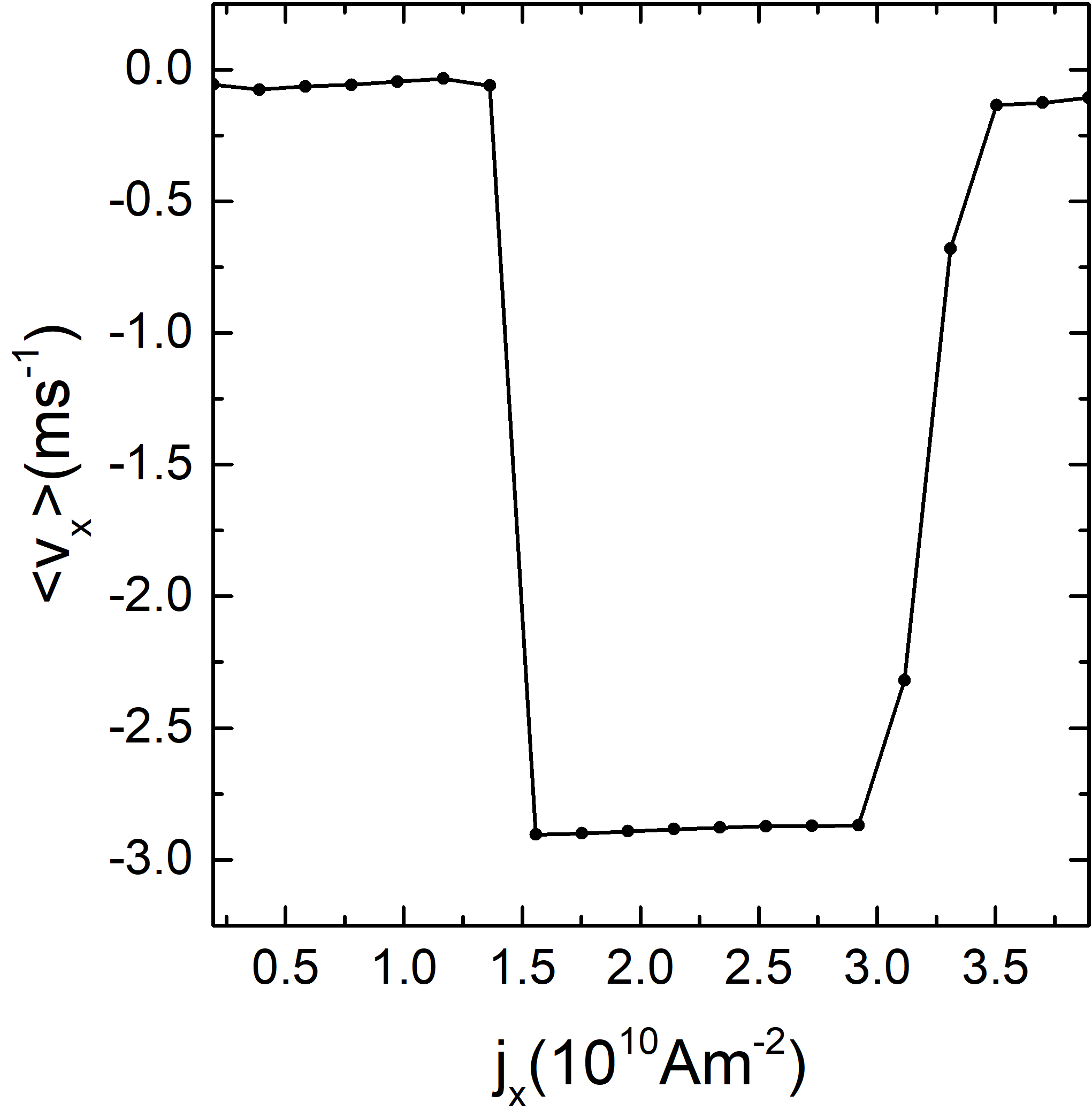
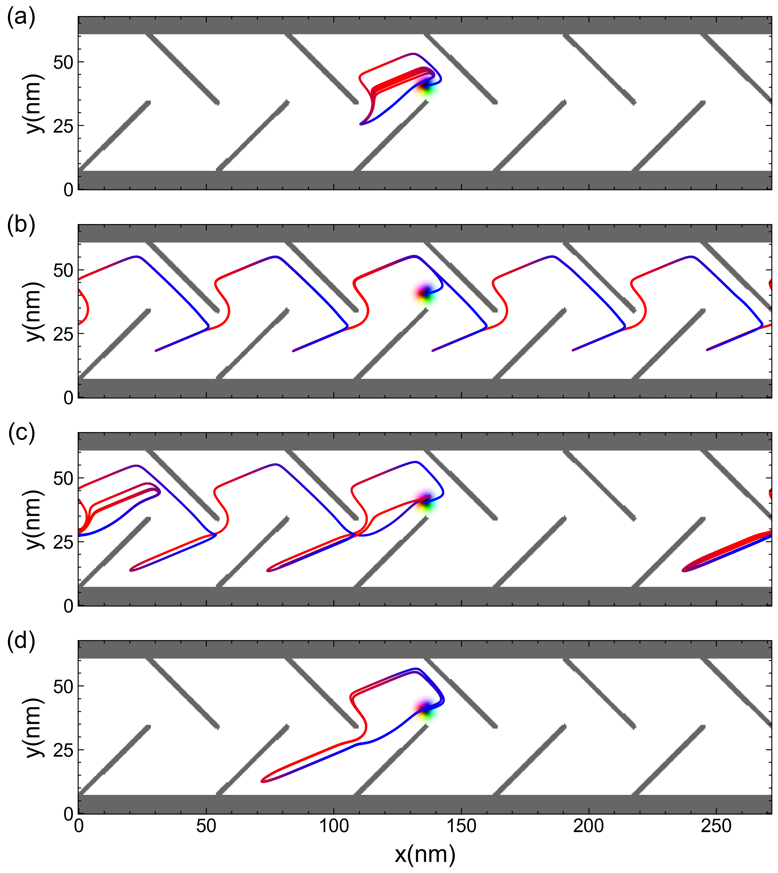
In Fig. 2 we plot the time average skyrmion velocity versus the ac amplitude . When , the average skyrmion velocity is nearly zero. This is the initial pinned phase (PP), and the slight deviation of the velocity from zero is produced by the brief initial period of time during which the skyrmion orbit adjusts to changes in the ac driving amplitude. A representative skyrmion trajectory showing this transient motion is illustrated in Fig. 3(a). As increases, the skyrmion orbit increases in size and becomes more unstable. At , the skyrmion velocity increases abruptly to ms-1, indicating that a depinning threshold has been crossed. The net motion of the skyrmion along the direction in this phase is associated with an orbit that is too large to be stabilized between the linear protrusions, and therefore evolves into a translating orbit that carries the skyrmion across the sample. For , the skyrmion is in a constant velocity phase (CVP) with a translating orbit that gives ms-1. The skyrmion flow in the direction occurs along the hard substrate asymmetry direction, and the skyrmion must overcome the divots of the array in order to flow. The skyrmion trajectory in the CVP is shown in Fig. 3(b). The constant velocity is maintained even as varies because the skyrmion translates by exactly one plaquette during each ac drive cycle, and the driving frequency is being held constant. For , the system transitions to a reentrant pinning phase (RPP). The average skyrmion velocity in the RPP is again not exactly zero due to the transient adjustment of the orbit each time is modified. As increases, when the RPP arises a new stable localized orbit develops that is much more elongated than the orbit in the PP, as illustrated in Fig. 3(c) and (d). The portion of the orbit extending along the direction becomes so extended that the skyrmion gets trapped underneath one of the linear defects and is no longer able to jump into a neighboring plaquette during the portion of the ac drive cycle. This reentrant transition into a pinned state is not as sharp as the depinning transition found at lower since the trapping process at high is more gradual than the escape process at low .
For ac driving along the direction, we observe three distinctive phases with well defined behavior. The CVP, where the average skyrmion velocity is constant, can be useful for spintronic devices where precise control of the skyrmion motion is crucial. In addition, the skyrmion motion can be switched on or off by a fine adjustment in the external ac drive magnitude across the depinning transition. Although we performed simulations only for , we expect that similar behavior will occur for larger values of . In particular, as increases, the size of the skyrmion orbit can continue to increase and may become unstable again, leading to the reemergence of a translating orbit.
III.1 Influence of the frequency
The motion described previously showed three distinctive phases at fixed , with well defined ranges of for each phase. We next investigate how the frequency of the ac drive affects the dynamics by varying it over the range and using the same range of values from before.
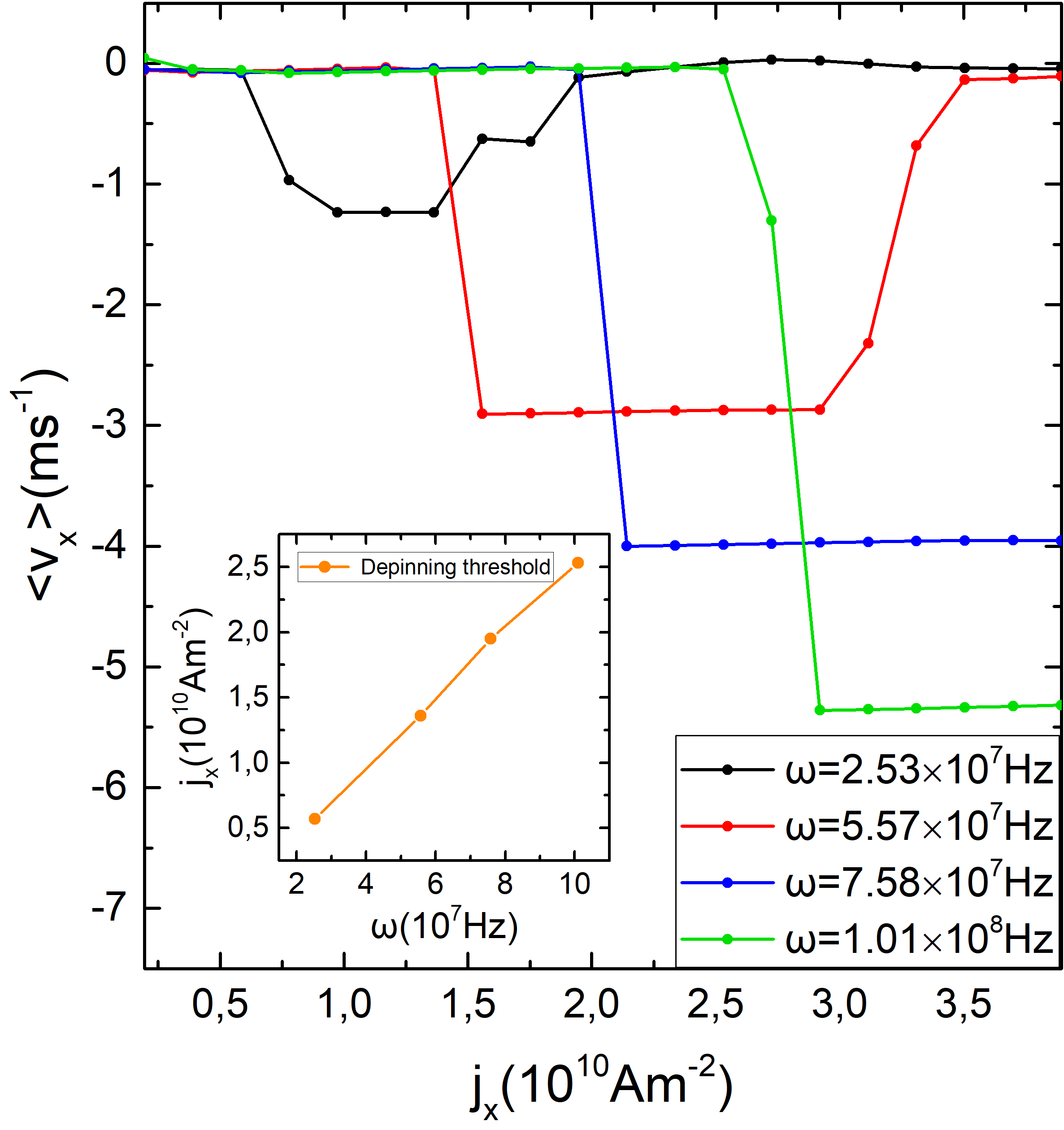
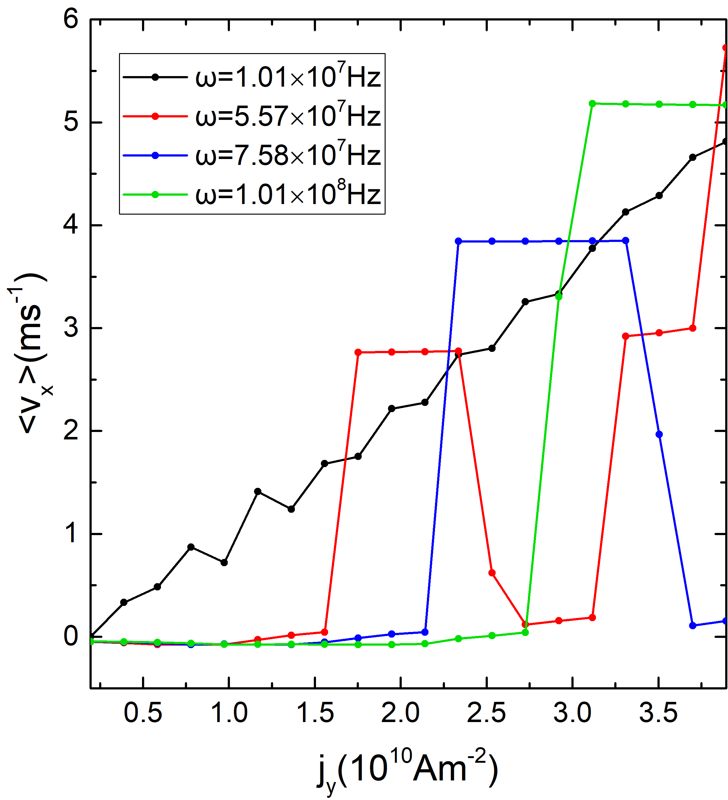
In Fig. 4 we plot the average skyrmion velocity versus for different values of . The behavior is similar in each case. The PP appears for all values of . The CVP is also observed for all values of ; however, the width of this phase is strongly affected by . As increases, the onset of the CVP shifts towards higher values of , so that the range of the PP becomes larger. This is more easily visible in the inset of Fig. 4, where we plot the depinning threshold versus and find a linear dependence. The increase in the depinning threshold occurs due to the oscillatory nature of the ac drive. As increases, the oscillations in the driving direction occur more rapidly, causing the skyrmion to experience a force in any given direction for a shorter period of time, and shrinking the skyrmion orbit accordingly. Thus, a larger current amplitude must be applied at higher in order to generate an orbit that is unstable enough to delocalize and produce net dc motion. Another interesting effect in Fig. 4 is the increase in the magnitude of the average skyrmion velocity in the CVP with increasing . Higher applied currents result in dc motion with enhanced velocities. Additionally, as increases, the CVP extends up to higher values of . This is analogous to the increase of the depinning threshold as a function of ; for higher values, larger values of must be applied in order to obtain a skyrmion orbit that is large enough to reach the RPP. For the highest value of , Hz, the RPP is not observed over the range of simulated here; however, we expect that the RPP would appear at even higher values of .
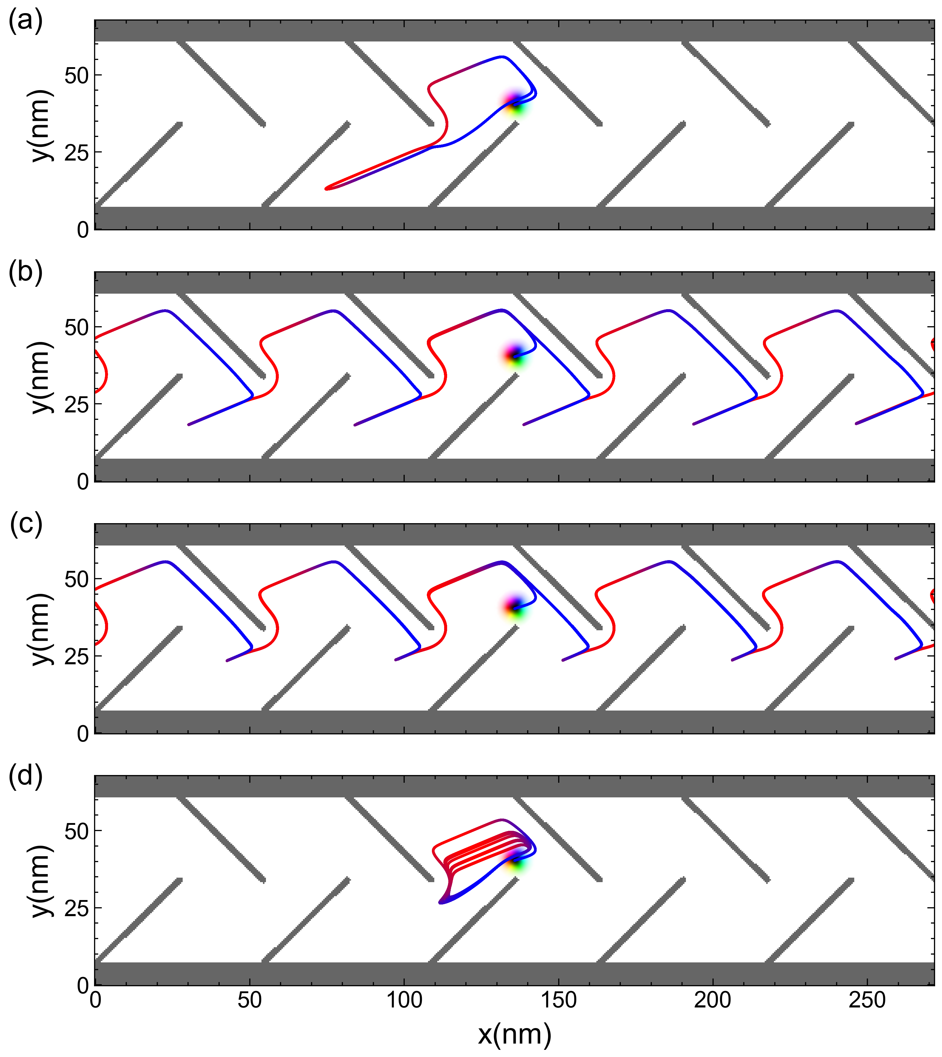
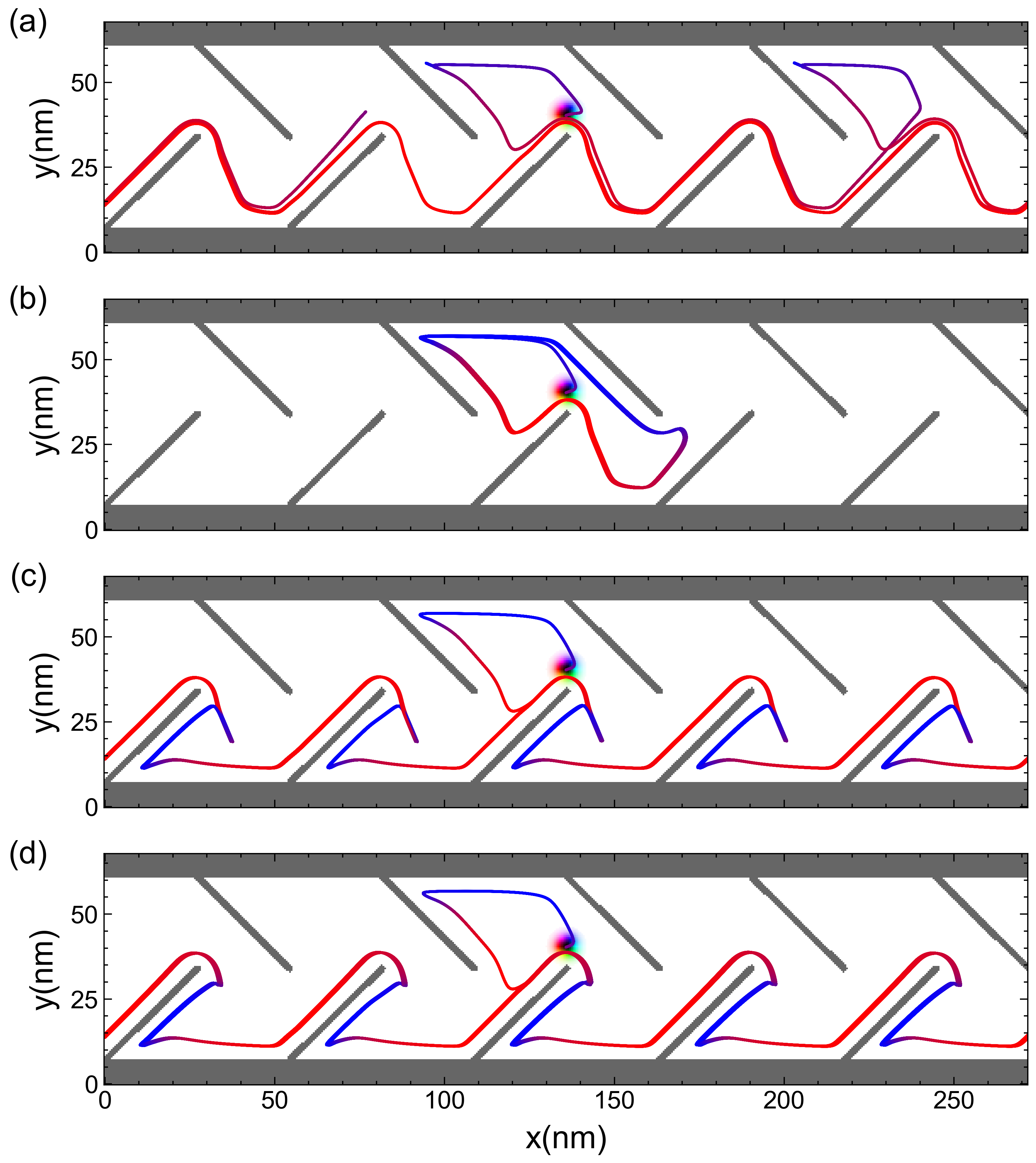
Figure 5 illustrates the skyrmion trajectory at different values of . In Fig. 5(a) at Hz, the skyrmion is trapped in the RPP. As increases, the skyrmion orbit becomes narrower and extends less far along the direction until the skyrmion no longer experiences confinement underneath a linear defect. When this occurs, the localized orbit destabilizes, permitting the CVP to appear with a translating orbit as shown in Fig. 5(b) for Hz. In Fig. 5(c) at Hz, the skyrmion is still in the CVP, but due to the increased ac frequency, the dead end portion of the orbit extending in the direction becomes less pronounced. When Hz, the frequency is so high that the orbit is no longer wide enough for the skyrmion to slip past the linear defect into the next plaquette, and the PP emerges, as shown in Fig. 5(d).
III.2 Conditions for skyrmion transport with ac drive along the direction
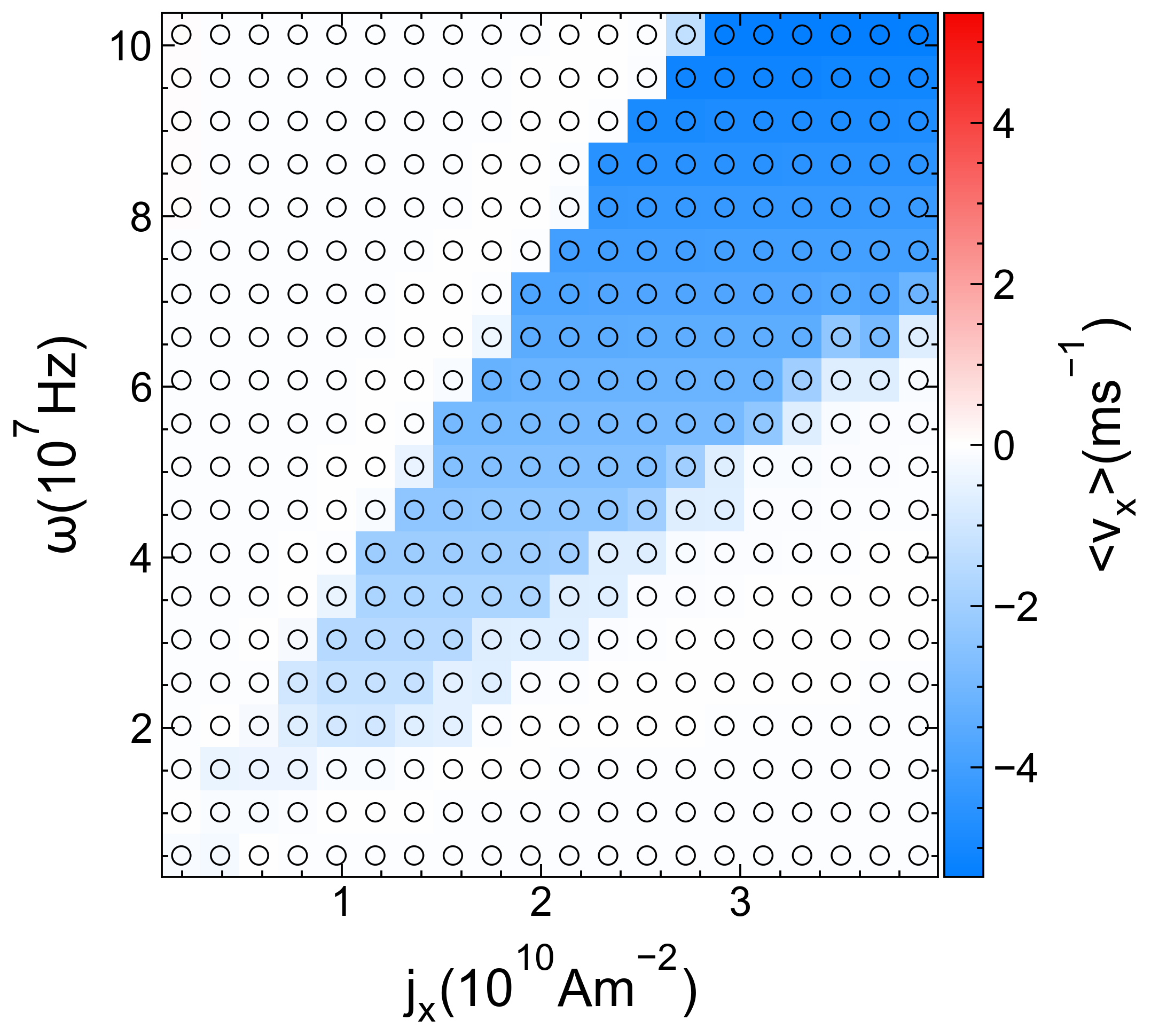
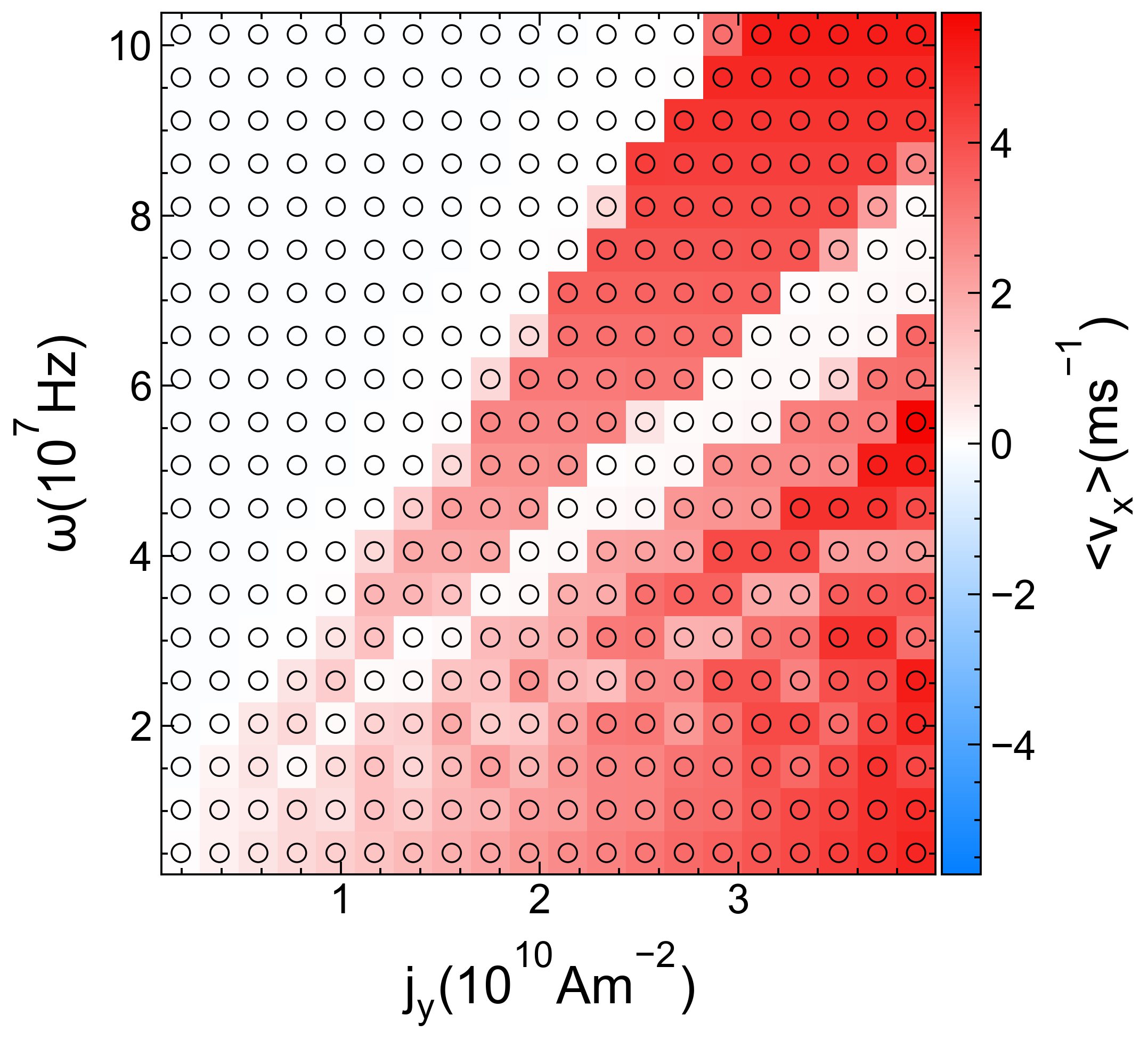
Now that we understand the individual effects of both ac drive magnitude, , and the ac drive frequency, , for ac driving in the direction, we perform a series of simulations in which we vary both parameters and identify the optimal conditions for skyrmion transport. In Fig. 6 we plot a heatmap of the skyrmion average velocity as a function of versus . Both the PP and RPP appear as white regions since both of these phases have very low velocities. They are separated by the blue region, which represents the CVP. For values of and falling above the blue region, the system is in the PP, where the skyrmion exhibits no net motion and the trajectories are very similar to those shown in Fig. 5(d) and Fig. 3(a). For and values that are below the blue region, the system is in the RPP, where the skyrmion has no net motion and the trajectory is similar to those shown in Fig. 5(a) and Fig. 3(d). In the CVP phase, the skyrmion trajectories are similar to those shown in Fig. 5(b,c) and Fig. 3(b). The speed at which the skyrmion is transported along the sample in the CVP is governed by . Note that as increases, the blue region becomes darker, indicating higher velocity magnitudes. Additionally, the onset of skyrmion transport and the range of values for which it occurs also change as varies.
Figure 6 can be very useful for the design of a device using a linear protrusion array of defects, since it clearly shows the necessary parameters for skyrmion transport through the sample. In addition, it indicates how rapidly the skyrmion can be transported in the CVP. In our simulations, the skyrmion is always stable and we did not observe any annihilation effects, which is crucial for technological applications where skyrmions are to be used as information carriers. We expect, however, that if a much stronger ac drive amplitude is applied, the skyrmion may be annihilated when it comes into contact with the linear protrusion magnetic walls.
IV Ac drive along the direction
In Section III we showed that applying the ac drive along the direction may induce skyrmion transport in the direction. Here, we investigate the same system from Fig. 1 but apply the ac drive along the direction, giving and .
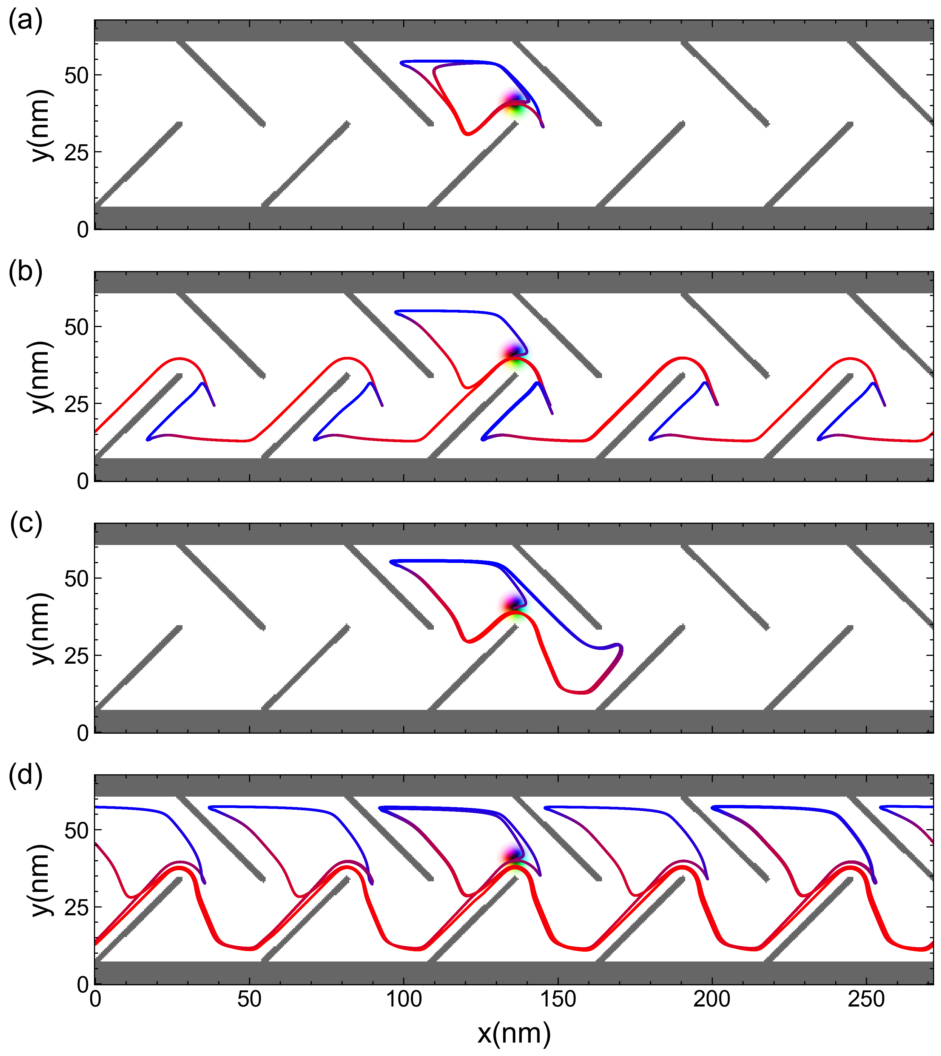
In Fig. 7 we plot the skyrmion average velocity as a function of the ac drive amplitude for fixed Hz. We find several different dynamic regimes that we can classify as a pinned phase (PP), a reentrant pinned phase (RPP), and different types of constant velocity phases (CVPs). For Am-2, the skyrmion exhibits no net motion and is in the PP as illustrated in Fig. 8(a). As was the case for driving, we find that the velocities are not exactly zero since the skyrmion undergoes transient motion before the localized orbit becomes stabilized. In the interval , the skyrmion orbit is unstable and the dc velocity takes the value ms-1, indicating that the skyrmion is in the CVP illustrated in Fig. 8(b). Here the skyrmion translates by one plaquette during every ac drive cycle. The skyrmion has a greater interaction with the lower part of the sample when the ac driving is in the direction due to the skyrmion Hall angle effect, and the net transport is in the positive direction, unlike the case of direction ac driving which produced dc motion in the negative direction. Above , the skyrmion average velocity drops to a value that is very close to zero. In this region, a localized skyrmion orbit becomes stable again and the dc motion is lost, giving a RPP as shown in Fig. 8(c). Here the width of the skyrmion orbit matches the spacing between the linear protrusions. When , the localized orbit destabilizes because it is now too wide to fit inside a single plaquette, and dc motion reappears. Notice that the skyrmion is now translating by two plaquettes during every dc drive cycle. A blue orbit appears in the top portion of every plaquette only because the total number of plaquettes is odd. Figure 7 shows that the skyrmion velocity for the state in Fig. 8(d) is twice as large as that in Fig. 8(b). For larger values of , the skyrmion dynamics oscillate among a series of CVPs where the velocity locks to a constant value that differs from one CVP to the next and is determined by the number of plaquettes the skyrmion can translate in each ac drive cycle. In every CVP, the skyrmion follows a distinct delocalized orbit as it translates through the sample. Figure 8(d) shows an example of the skyrmion trajectory in the CVP at Am-2. The fact that the skyrmion translates along the easy direction of the substrate asymmetry for direction driving makes it possible for the skyrmion to move through multiple plaquettes per ac drive cycle, giving multiple CVP states. This is in contrast to the single CVP state found for direction driving, when the motion is along the hard direction of the substrate asymmetry and the translating orbit is confined by the substrate in such a way that the skyrmion can travel only exactly one plaquette during each ac drive cycle.
IV.1 Influence of the frequency
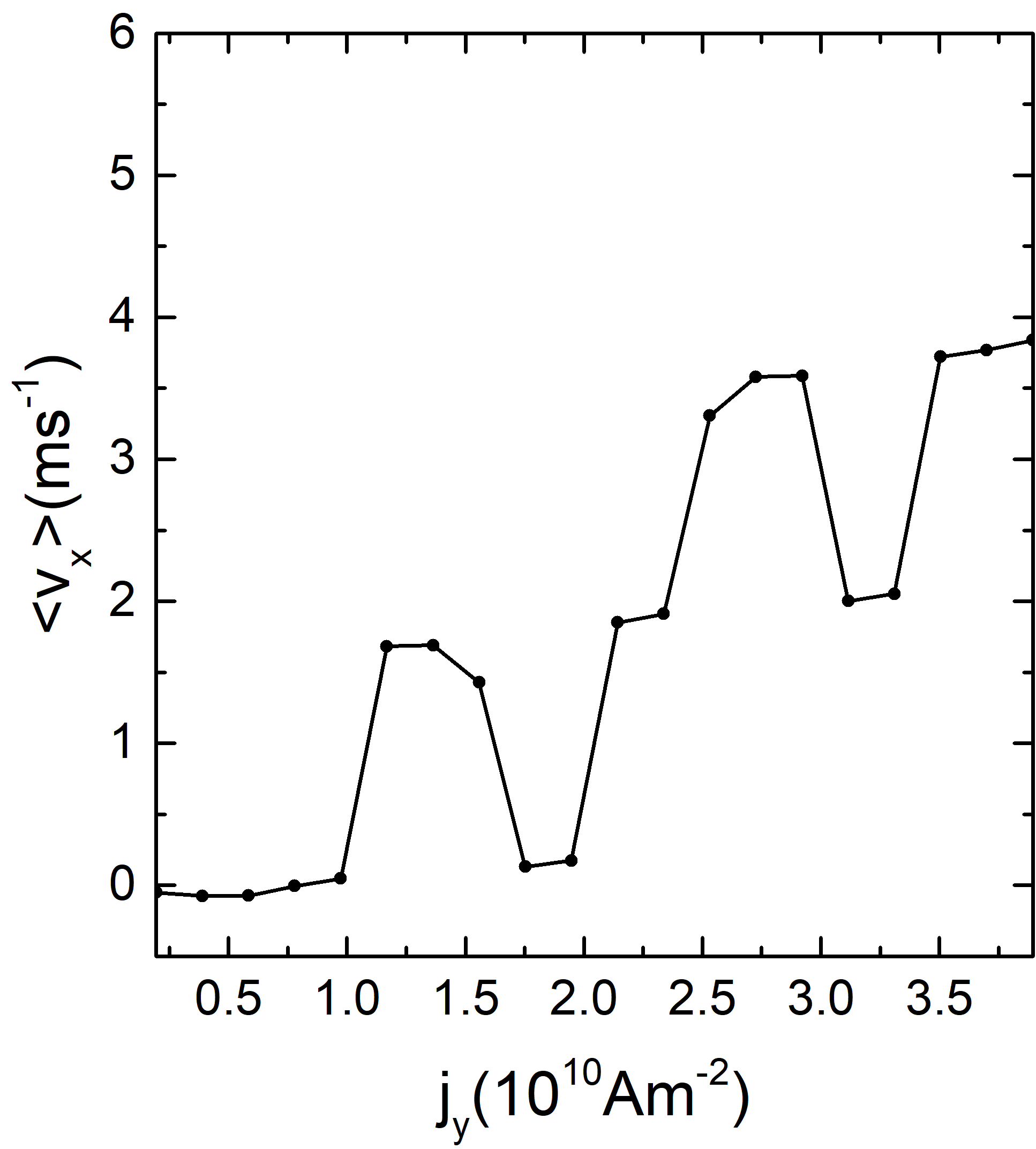
We next consider how the ac driving frequency affects the dynamics under direction driving by varying over the range . In Fig. 9 we plot the average skyrmion velocity versus for selected values of . When Hz, the CVP and RPP vanish. As low values of such as this one, the skyrmion can coast along the bottom of the array over a distance of many plaquettes during the portion of the ac drive cycle, as shown in Fig. 10(a) at Am-2. The Magnus term rotates the repulsive force from the protrusions and walls into a velocity, resulting in a Magnus velocity boost effect. The confined excursion into the upper portion of the sample provides only a small perturbation to the boosted velocity and is insufficient to quantize the velocity values. As a result, increases almost linearly with the ac drive amplitude . For Hz, Hz, and Hz, the behavior is similar to what was observed in in Fig. 7, with the CVP and RPP both present but extending over a wider range of values compared to the system with Hz. For Hz the skyrmion becomes trapped in a RPP, as illustrated in Fig. 10(b) at Am-2. Here the size of the skrymion orbit matches the length scale of the plaquette. For Hz at the same value of , the orbit is delocalized again and the skyrmion flows along the positive direction as shown in Fig. 10(c). Figure 9 indicates that the skyrmion average velocity in each CVP becomes larger for higher frequencies, as illustrated in Fig. 10(d) where we show another type of CVP with higher average velocity at Hz. The velocity increase is simply due to the higher ac driving frequency; the skyrmion still translates by one plaquette per ac drive cycle but the drive cycle is shorter at higher , so the skyrmion moves faster. The onset of the CVP in Fig. 9 shifts to higher with increasing because at high ac driving frequencies, the skyrmion orbits become narrower and so larger values of must be applied to destabilize the localized orbits.
IV.2 Conditions for skyrmion transport with ac drive along the direction
In Fig. 11 we plot a heatmap of the skyrmion average velocity as a function of the frequency versus the drive magnitude . There are two large red regions corresponding to the dynamic phases where the skyrmion is being transported. The white regions correspond to phases where the skyrmion exhibits no net motion. The first white region that occurs for lower values of is the PP where the localized skyrmion orbit is stabilized with no net motion. At slightly larger values of we find the first red region, corresponding to the CVP in which the localized skyrmion orbit is unstable and the skyrmion translates through the sample along the positive direction. In this phase, as increases, the range of where the CVP is stable increases, and the average skyrmion velocity also increases in a manner analogous to that discussed for Fig. 6. The second white region, located between two red regions, is the RPP, where the increase in stabilizes the previously unstable localized skyrmion orbit, resulting in a state with . In addition, as increases, the RPP expands over a wider range of . The second red region that occurs for larger values of corresponds to a mixture of CVP and a skyrmion transport phase in which the velocity increases almost linearly with . In this region, for larger values of the system is in a clearly defined CVP phase where multiple constant velocity states can be accessed by varying the ac drive amplitude. As is reduced, the CVP is lost and the skyrmion velocity increases linearly with . This is a result of the velocity boost effect from the Magnus term, which makes the motion during the and portions of the ac drive cycle very asymmetric and destroys the velocity quantization found for larger values of .
As we have seen, when the ac drive is applied along the direction, the skyrmion flows along , the hard substrate asymmetry direction, while when the ac drive is applied along the direction, the skyrmion instead flows along , the easy substrate asymmetry direction. The plots in Figs. 6 and 11 show in great detail the possibilities for achieving controlled skyrmion motion by tuning the values of and either or . We note that for the parameters we consider, no annihilation effects were observed; however, for sufficiently large ac drive amplitudes, we expect that the skyrmion would be pushed hard enough against the walls and linear protrusions that annihilation events would occur. Thus there is a finite range of ac driving where control of stable skyrmion motion can be achieved.
V Summary
Using an atomistic model for simulating individual atomic magnetic moments, we investigated the dynamical behavior of a single skyrmion interacting with a linear protrusion array of defects with ac driving applied along either the or directions in the absence of thermal effects. When the ac driving is parallel to the direction, the skyrmion can be transported along the negative or hard substrate asymmetry direction over a range of ac drive amplitudes. There are three distinct phases of motion. At low ac amplitudes, the skyrmion enters a stable localized orbit and has no net dc motion, giving a pinned phase. When the ac amplitude increases, the localized skyrmion orbit expands in size and becomes unstable, leading to the emergence of a constant velocity phase in which the skyrmion follows a translating orbit along the negative direction. As the ac driving amplitude becomes even larger, the skyrmion orbit continues to grow until a localized orbit restabilizes again due to confinement by the linear protrusions, resulting in a reentrant pinned phase with no net dc transport. When the ac drive frequency increases, we find that the range of ac drive amplitudes over which each phase is stable increases, and that the skyrmion average velocity in the constant velocity phase also increases.
When the ac drive is applied along the direction, the skyrmion can be transported along the positive or easy flow direction of the substrate asymmetry for a range of ac amplitudes. The velocity boost effect produced by the Magnus term for direction driving in the presence of the substrate permits a greater range of translating orbits to appear, and we observe a richer dynamical response compared to driving along the direction. At low values of ac drive amplitudes, the skyrmion orbit is localized and we find a pinned phase with no net motion. As the ac amplitude increases, the localized orbit destabilizes and the skyrmion enters a constant velocity phase in which it translates along the positive direction with constant velocity. Further increases in the ac drive amplitude restabilize a localized orbit, resulting in the emergence of a reentrant pinned phase with no net motion. For sufficiently high values of the ac drive amplitude, the skyrmion orbit becomes too large to localize, and we find a series of distinct constant velocity phases, each of which has a different average velocity value determined by the number of plaquettes the skyrmion traverses during each ac drive cycle. Just as in the case for direction ac driving, increasing the ac driving frequency for direction ac driving causes each phase to extend over a wider range of ac drive amplitudes and also increases the average velocity in the constant velocity phase. Above the reentrant pinning phase, the constant velocity phases become more stable as the ac frequency increases, while for small frequencies these phases disappear completely and are replaced by a regime in which the average skyrmion velocity increases linearly with increasing ac drive amplitude.
Our findings can be useful for realizing novel spintronic devices where controlled skyrmion motion is crucial. In our system, the ability to control the direction and velocity of the skyrmion motion makes it possible to efficiently transport information in a device where the skyrmion serves as an information carrier. The level of skyrmion control that we obtain in our sample is similar to the control achieved in Ref. Souza et al. (2021), where the skyrmion is also controlled precisely using ac currents. The key difference from the previous work is that in the linear protrusion device considered here, the skyrmion average velocities are similar for transport in both the positive and negative directions, resulting in a more energy-efficiency skyrmion transport overall.
Acknowledgments
This work was supported by the US Department of Energy through the Los Alamos National Laboratory. Los
Alamos National Laboratory is operated by Triad National Security, LLC, for the National Nuclear Security
Administration of the U. S. Department of Energy (Contract No. 892333218NCA000001).
J.C.B.S acknowledges funding from Fundação de Amparo à Pesquisa do Estado de São Paulo - FAPESP (Grant 2022/14053-8).
We would like to thank Dr. Felipe F. Fanchini for providing the computational resources used in this work.
These resources were funded by the Fundação de Amparo à Pesquisa do Estado de São Paulo - FAPESP (Grant: 2021/04655-8).
References
- Negru et al. (2013) C. Negru, F. Pop, V. Cristea, N. Bessisy, and J. Li, “Energy efficient cloud storage service: Key issues and challenges,” in 2013 Fourth International Conference on Emerging Intelligent Data and Web Technologies (2013) pp. 763–766.
- Nagaosa and Tokura (2013) N. Nagaosa and Y. Tokura, “Topological properties and dynamics of magnetic skyrmions,” Nature Nanotechnol. 8, 899–911 (2013).
- Je et al. (2020) S.-G. Je, H.-S. Han, S. K. Kim, S. A. Montoya, W. Chao, I.-S. Hong, E. E. Fullerton, K.-S. Lee, K.-J. Lee, M.-Y. Im, and J.-I. Hong, “Direct demonstration of topological stability of magnetic skyrmions via topology manipulation,” ACS Nano 14, 3251–3258 (2020).
- Wang et al. (2018) X. S. Wang, H. Y. Yuan, and X. R. Wang, “A theory on skyrmion size,” Commun. Phys. 1, 31 (2018).
- Mühlbauer et al. (2009) S. Mühlbauer, B. Binz, F. Jonietz, C. Pfleiderer, A. Rosch, A. Neubauer, R. Georgii, and P. Böni, “Skyrmion lattice in a chiral magnet,” Science 323, 915–919 (2009).
- Yu et al. (2010) X. Z. Yu, Y. Onose, N. Kanazawa, J. H. Park, J. H. Han, Y. Matsui, N. Nagaosa, and Y. Tokura, “Real-space observation of a two-dimensional skyrmion crystal,” Nature 465, 901–904 (2010).
- Pfleiderer et al. (2010) C. Pfleiderer, T. Adams, A. Bauer, W. Biberacher, B. Binz, F. Birkelbach, P. Böni, C. Franz, R. Georgii, M. Janoschek, F. Jonietz, T. Keller, R. Ritz, S. Mühlbauer, W. Münzer, A. Neubauer, B. Pedersen, and A. Rosch, “Skyrmion lattices in metallic and semiconducting b20 transition metal compounds,” J. Phys.: Condensed Matter 22, 164207 (2010).
- Münzer et al. (2010) W. Münzer, A. Neubauer, T. Adams, S. Mühlbauer, C. Franz, F. Jonietz, R. Georgii, P. Böni, B. Pedersen, M. Schmidt, A. Rosch, and C. Pfleiderer, “Skyrmion lattice in the doped semiconductor Fe1-xCoxSi,” Phys. Rev. B 81, 041203 (2010).
- Everschor-Sitte et al. (2018) K. Everschor-Sitte, J. Masell, R. M. Reeve, and M. Kläui, “Perspective: Magnetic skyrmions—Overview of recent progress in an active research field,” J. Appl. Phys. 124, 240901 (2018).
- Fert et al. (2013) A. Fert, V. Cros, and J. Sampaio, “Skyrmions on the track,” Nature Nanotechnol. 8, 152–156 (2013).
- Fert et al. (2017) A. Fert, N. Reyren, and V. Cros, “Magnetic skyrmions: advances in physics and potential applications,” Nature Rev. Mater. 2, 1–15 (2017).
- Schulz et al. (2012) T. Schulz, R. Ritz, A. Bauer, M. Halder, M. Wagner, C. Franz, C. Pfleiderer, K. Everschor, M. Garst, and A. Rosch, “Emergent electrodynamics of skyrmions in a chiral magnet,” Nature Phys. 8, 301–304 (2012).
- Jonietz et al. (2010) F. Jonietz, S. Mühlbauer, C. Pfleiderer, A. Neubauer, W. Münzer, A. Bauer, T. Adams, R. Georgii, P. Böni, R. A. Duine, K. Everschor, M. Garst, and A. Rosch, “Spin transfer torques in MnSi at ultralow current densities,” Science 330, 1648–1651 (2010).
- Luo and You (2021) S. Luo and L. You, “Skyrmion devices for memory and logic applications,” APL Mater. 9, 50901 (2021).
- Shu et al. (2022) Y. Shu, Q. Li, J. Xia, P. Lai, Z. Hou, Y. Zhao, D. Zhang, Y. Zhou, X. Liu, and G. Zhao, “Realization of the skyrmionic logic gates and diodes in the same racetrack with enhanced and modified edges,” Appl. Phys. Lett. 121, 42402 (2022).
- Zhang et al. (2015a) Xichao Zhang, Motohiko Ezawa, and Yan Zhou, “Magnetic skyrmion logic gates: conversion, duplication and merging of skyrmions,” Scientific Reports 5, 9400 (2015a).
- Bellizotti Souza et al. (2022) J. C. Bellizotti Souza, N. Vizarim, C. J. O. Reichhardt, C. Reichhardt, and P. A. Venegas, “Magnus induced diode effect for skyrmions in channels with periodic potentials,” J. Phys.: Condensed Matter 51, 015804 (2022).
- Feng et al. (2022) Y. Feng, X. Zhang, G. Zhao, and G. Xiang, “A skyrmion diode based on skyrmion Hall effect,” IEEE Trans. Electron Devices 69, 1293 (2022).
- Wang et al. (2020) J. Wang, J. Xia, X. Zhang, X. Zheng, G. Li, L. Chen, Y. Zhou, J. Wu, H. Yin, R. Chantrell, and Y. Xu, “Magnetic skyrmionium diode with a magnetic anisotropy voltage gating,” Appl. Phys. Lett. 117, 202401 (2020).
- Song et al. (2020) K. M. Song, J.-S. Jeong, B. Pan, X. Zhang, J. Xia, S. Cha, T.-E. Park, K. Kim, S. Finizio, J. Raabe, J. Chang, Y. Zhou, W. Zhao, W. Kang, H. Ju, and S. Woo, “Skyrmion-based artificial synapses for neuromorphic computing,” Nature Electronics 3, 148–155 (2020).
- Jung et al. (2021) D.-H. Jung, H.-S. Han, N. Kim, G. Kim, S. Jeong, S. Lee, M. Kang, M.-Y. Im, and K.-S. Lee, “Magnetic skyrmion diode: Unidirectional skyrmion motion via symmetry breaking of potential energy barriers,” Phys. Rev. B 104, L060408 (2021).
- Zhao et al. (2020) L. Zhao, X. Liang, J. Xia, G. Zhao, and Y. Zhou, “A ferromagnetic skyrmion-based diode with a voltage-controlled potential barrier,” Nanoscale 17, 9507 (2020).
- Zhang et al. (2015b) X. Zhang, Y. Zhou, M. Ezawa, G. P. Zhao, and W. Zhao, “Magnetic skyrmion transistor: skyrmion motion in a voltage-gated nanotrack,” Sci. Rep. 5, 11369 (2015b).
- Msiska et al. (2023) R. Msiska, J. Love, J. Mulkers, J. Leliaert, and K. Everschor-Sitte, “Audio classification with skyrmion reservoirs,” Adv. Intell. Syst. 5, 2200388 (2023).
- Li et al. (2017) S. Li, W. Kang, Y. Huang, X. Zhang, Y. Zhou, and W. Zhao, “Magnetic skyrmion-based artificial neuron device,” Nanotechnol. 28, 31LT01 (2017).
- Li et al. (2021) S. Li, W. Kang, X. Zhang, T. Nie, Y. Zhou, K. L. Wang, and W. Zhao, “Magnetic skyrmions for unconventional computing,” Mater. Horizons 8, 854–868 (2021).
- Luo et al. (2018) S. Luo, M. Song, X. Li, Y. Zhang, J. Hong, X. Yang, X. Zou, N. Xu, and L. You, “Reconfigurable skyrmion logic gates,” Nano Lett. 18, 1180–1184 (2018).
- Zhang et al. (2023a) X. Zhang, J. Xia, O. A. Tretiakov, M. Ezawa, G. Zhao, Y. Zhou, X. Liu, and M. Mochizuki, “Laminar and transiently disordered dynamics of magnetic-skyrmion pipe flow,” Phys. Rev. B 108, 144428 (2023a).
- Pfleiderer (2011) C. Pfleiderer, “Surfaces get hairy,” Nature Phys. 7, 673–674 (2011).
- Wiesendanger (2016) R. Wiesendanger, “Nanoscale magnetic skyrmions in metallic films and multilayers: a new twist for spintronics,” Nature Rev. Mater. 1, 1–11 (2016).
- Kang et al. (2016) W. Kang, Y. Huang, X. Zhang, Y. Zhou, and W. Zhao, “Skyrmion-electronics: An overview and outlook,” Proc. IEEE 104, 2040–2061 (2016).
- Zhang et al. (2020) X. Zhang, Y. Zhou, K. M. Song, T.-E. Park, J. Xia, M. Ezawa, X. Liu, W. Zhao, G. Zhao, and S. Woo, “Skyrmion-electronics: Writing, deleting, reading and processing magnetic skyrmions toward spintronic applications,” J. Phys.: Condensed Matter 32, 143001 (2020).
- Olson Reichhardt et al. (2014) C. J. Olson Reichhardt, S. Z. Lin, D. Ray, and C. Reichhardt, “Comparing the dynamics of skyrmions and superconducting vortices,” Physica C 503, 52–57 (2014).
- Reichhardt and Reichhardt (2016) C. Reichhardt and C. J. Olson Reichhardt, “Depinning and nonequilibrium dynamic phases of particle assemblies driven over random and ordered substrates: a review,” Rep. Prog. Phys. 80, 26501 (2016).
- Litzius et al. (2017) K. Litzius, I. Lemesh, B. Krüger, P. Bassirian, L. Caretta, K. Richter, F. Büttner, K. Sato, O. A. Tretiakov, J. Förster, R. M. Reeve, M. Weigand, I. Bykova, H. Stoll, G. Schütz, G. S. D. Beach, and M. Kläui, “Skyrmion Hall effect revealed by direct time-resolved X-ray microscopy,” Nature Phys. 13, 170–175 (2017).
- Iwasaki et al. (2013a) J. Iwasaki, M. Mochizuki, and N. Nagaosa, “Universal current-velocity relation of skyrmion motion in chiral magnets,” Nature Commun. 4, 1463 (2013a).
- Jiang et al. (2017) W. Jiang, X. Zhang, G. Yu, W. Zhang, X. Wang, M. B. Jungfleisch, J. E. Pearson, X. Cheng, O. Heinonen, K. L. Wang, Y. Zhou, A. Hoffmann, and S. G. E. te Velthuis, “Direct observation of the skyrmion Hall effect,” Nature Phys. 13, 162–169 (2017).
- Lin et al. (2013a) S.-Z. Lin, C. Reichhardt, C. D. Batista, and A. Saxena, “Driven skyrmions and dynamical transitions in chiral magnets,” Phys. Rev. Lett. 110, 207202 (2013a).
- Lin et al. (2013b) S.-Z. Lin, C. Reichhardt, C. D. Batista, and A. Saxena, “Particle model for skyrmions in metallic chiral magnets: Dynamics, pinning, and creep,” Phys. Rev. B 87, 214419 (2013b).
- Zeissler et al. (2020) K. Zeissler, S. Finizio, C. Barton, A. J. Huxtable, J. Massey, J. Raabe, A. V. Sadovnikov, S. A. Nikitov, R. Brearton, T. Hesjedal, G. van der Laan, M. C. Rosamond, E. H. Linfield, G. Burnell, and C. H. Marrows, “Diameter-independent skyrmion Hall angle observed in chiral magnetic multilayers,” Nature Commun. 11, 428 (2020).
- Reichhardt et al. (2015a) C. Reichhardt, D. Ray, and C. J. Olson Reichhardt, “Quantized transport for a skyrmion moving on a two-dimensional periodic substrate,” Phys. Rev. B 91, 104426 (2015a).
- Reichhardt et al. (2018) C. Reichhardt, D. Ray, and C. J. O. Reichhardt, “Nonequilibrium phases and segregation for skyrmions on periodic pinning arrays,” Phys. Rev. B 98, 134418 (2018).
- Feilhauer et al. (2020) J. Feilhauer, S. Saha, J. Tobik, M. Zelent, L. J. Heyderman, and M. Mruczkiewicz, “Controlled motion of skyrmions in a magnetic antidot lattice,” Phys. Rev. B 102, 184425 (2020).
- Vizarim et al. (2021a) N. P. Vizarim, J. C. Bellizotti Souza, C. Reichhardt, C. J. O. Reichhardt, and P. A. Venegas, “Directional locking and the influence of obstacle density on skyrmion dynamics in triangular and honeycomb arrays,” J. Phys.: Condensed Matter 33, 305801 (2021a).
- Vizarim et al. (2020) N. P. Vizarim, C. Reichhardt, C. J. O. Reichhardt, and P. A. Venegas, “Skyrmion dynamics and topological sorting on periodic obstacle arrays,” New J. Phys. 22, 53025 (2020).
- Reichhardt and Reichhardt (2022) C. Reichhardt and C. J. O. Reichhardt, “Commensuration effects on skyrmion Hall angle and drag for manipulation of skyrmions on two-dimensional periodic substrates,” Phys. Rev. B 105, 214437 (2022).
- Carvalho-Santos et al. (2021) V. L. Carvalho-Santos, M. A. Castro, D. Salazar-Aravena, D. Laroze, R. M. Corona, S. Allende, and D. Altbir, “Skyrmion propagation along curved racetracks,” Appl. Phys. Lett. 118, 172407 (2021).
- Korniienko et al. (2020) A. Korniienko, A. Kákay, D. D. Sheka, and V. P. Kravchuk, “Effect of curvature on the eigenstates of magnetic skyrmions,” Phys. Rev. B 102, 014432 (2020).
- Yershov et al. (2022) K. V. Yershov, A. Kákay, and V. P. Kravchuk, “Curvature-induced drift and deformation of magnetic skyrmions: Comparison of the ferromagnetic and antiferromagnetic cases,” Phys. Rev. B 105, 054425 (2022).
- Vizarim et al. (2021b) N. P. Vizarim, C. Reichhardt, P. A. Venegas, and C. J. O. Reichhardt, “Guided skyrmion motion along pinning array interfaces,” J. Mag. Mag. Mater. 528, 167710 (2021b).
- Zhang et al. (2022a) C.-L. Zhang, J.-N. Wang, C.-K. Song, N. Mehmood, Z.-Z. Zeng, Y.-X. Ma, J.-B. Wang, and Q.-F. Liu, “Edge-guided heart-shaped skyrmion,” Rare Metals 41, 865–870 (2022a).
- Reichhardt et al. (2015b) C. Reichhardt, D. Ray, and C. J. Olson Reichhardt, “Magnus-induced ratchet effects for skyrmions interacting with asymmetric substrates,” New J. Phys. 17, 73034 (2015b).
- Souza et al. (2021) J. C. Bellizotti Souza, N. P. Vizarim, C. J. O. Reichhardt, C. Reichhardt, and P. A. Venegas, “Skyrmion ratchet in funnel geometries,” Phys. Rev. B 104, 54434 (2021).
- Chen et al. (2019) W. Chen, L. Liu, Y. Ji, and Y. Zheng, “Skyrmion ratchet effect driven by a biharmonic force,” Phys. Rev. B 99, 64431 (2019).
- Göbel and Mertig (2021) B. Göbel and I. Mertig, “Skyrmion ratchet propagation: utilizing the skyrmion Hall effect in AC racetrack storage devices,” Sci. Rep. 11, 3020 (2021).
- Yanes et al. (2019) R. Yanes, F. Garcia-Sanchez, R. F. Luis, E. Martinez, V. Raposo, L. Torres, and L. Lopez-Diaz, “Skyrmion motion induced by voltage-controlled in-plane strain gradients,” Appl. Phys. Lett. 115, 132401 (2019).
- Zhang et al. (2018) S. L. Zhang, W. W. Wang, D. M. Burn, H. Peng, H. Berger, A. Bauer, C. Pfleiderer, G. van der Laan, and T. Hesjedal, “Manipulation of skyrmion motion by magnetic field gradients,” Nature Commun. 9, 2115 (2018).
- Everschor et al. (2012) K. Everschor, M. Garst, B. Binz, F. Jonietz, S. Mühlbauer, C. Pfleiderer, and A. Rosch, “Rotating skyrmion lattices by spin torques and field or temperature gradients,” Phys. Rev. B 86, 54432 (2012).
- Kong and Zang (2013) L. Kong and J. Zang, “Dynamics of an insulating skyrmion under a temperature gradient,” Phys. Rev. Lett. 111, 67203 (2013).
- Menezes et al. (2019) R. M. Menezes, J. F. S. Neto, C. C. de Souza Silva, and M. V. Milošević, “Manipulation of magnetic skyrmions by superconducting vortices in ferromagnet-superconductor heterostructures,” Phys. Rev. B 100, 14431 (2019).
- Neto and Silva (2022) J. F. Neto and C. C. de Souza Silva, “Mesoscale phase separation of skyrmion-vortex matter in chiral-magnet–superconductor heterostructures,” Phys. Rev. Lett. 128, 057001 (2022).
- Zhang et al. (2022b) X. Zhang, J. Xia, and X. Liu, “Structural transition of skyrmion quasiparticles under compression,” Phys. Rev. B 105, 184402 (2022b).
- Bellizotti Souza et al. (2023) J. C. Bellizotti Souza, N. P. Vizarim, C. J. O. Reichhardt, C. Reichhardt, and P. A. Venegas, “Spontaneous skyrmion conformal lattice and transverse motion during dc and ac compression,” New J. Phys. 25, 053020 (2023).
- Vizarim et al. (2022) N. P. Vizarim, J. C. Bellizotti Souza, C. J. O. Reichhardt, C. Reichhardt, M. V. Milošević, and P. A. Venegas, “Soliton motion in skyrmion chains: Stabilization and guidance by nanoengineered pinning,” Phys. Rev. B 105, 224409 (2022).
- Souza et al. (2023) J. C. Bellizotti Souza, N. P. Vizarim, C. J. O. Reichhardt, C. Reichhardt, and P. A. Venegas, “Soliton motion induced along ferromagnetic skyrmion chains in chiral thin nanotracks,” J. Mag. Mag. Mater. 587, 171280 (2023).
- Zhang et al. (2023b) X. Zhang, J. Xia, O. A. Tretiakov, M. Ezawa, G. Zhao, Y. Zhou, X. Liu, and M. Mochizuki, “Chiral skyrmions interacting with chiral flowers,” (2023b).
- Wambaugh et al. (1999) J. F. Wambaugh, C. Reichhardt, C. J. Olson, F. Marchesoni, and F. Nori, “Superconducting fluxon pumps and lenses,” Phys. Rev. Lett. 83, 5106–5109 (1999).
- Vlasko-Vlasov et al. (2013) V. Vlasko-Vlasov, T. Benseman, U. Welp, and W. K. Kwok, “Jamming of superconducting vortices in a funnel structure,” Supercond. Sci. Technol. 26, 75023 (2013).
- Souza et al. (2022) J. C. Bellizotti Souza, N. P. Vizarim, C. J. O. Reichhardt, C. Reichhardt, and P. A. Venegas, “Clogging, diode and collective effects of skyrmions in funnel geometries,” New J. Phys. 24, 103030 (2022).
- Martinez et al. (2020) R. Martinez, F. Alarcon, J. Luis Aragones, and C. Valeriani, “Trapping flocking particles with asymmetric obstacles,” Soft Matter 16, 4739–4745 (2020).
- Gonzalez et al. (2007) E. M. Gonzalez, N. O. Nunez, J. V. Anguita, and J. L. Vicent, “Transverse rectification in superconducting thin films with arrays of asymmetric defects,” Appl. Phys. Lett. 91, 62505 (2007).
- Lu et al. (2007) Q. Lu, C. J. Olson Reichhardt, and C. Reichhardt, “Reversible vortex ratchet effects and ordering in superconductors with simple asymmetric potential arrays,” Phys. Rev. B 75, 54502 (2007).
- Olson Reichhardt and Reichhardt (2013) C. J. Olson Reichhardt and C. Reichhardt, “Vortex clogging, commensuration, and diodes in asymmetric constriction arrays,” J. Supercond. Novel Mag. 26, 2005–2008 (2013).
- Villegas et al. (2005) J. E. Villegas, E. M. Gonzalez, M. P. Gonzalez, J. V. Anguita, and J. L. Vicent, “Experimental ratchet effect in superconducting films with periodic arrays of asymmetric potentials,” Phys. Rev. B 71, 24519 (2005).
- Yu et al. (2007) K. Yu, T. W. Heitmann, C. Song, M. P. DeFeo, B. L. T. Plourde, M. B. S. Hesselberth, and P. H. Kes, “Asymmetric weak-pinning superconducting channels: Vortex ratchets,” Phys. Rev. B 76, 220507 (2007).
- Wells (2017) F. S. Wells, Investigating Vortex Behaviour in Superconducting Thin Films through Magnetic Microscopy Techniques, Ph.D. thesis, University of Wollongong (2017).
- Evans (2018) R. F. L. Evans, “Atomistic spin dynamics,” in Handbook of Materials Modeling: Applications: Current and Emerging Materials, edited by W. Andreoni and S. Yip (Springer International Publishing, 2018) pp. 1–23.
- Iwasaki et al. (2013b) J. Iwasaki, M. Mochizuki, and N. Nagaosa, “Current-induced skyrmion dynamics in constricted geometries,” Nature Nanotechnol. 8, 742–747 (2013b).
- Seki and Mochizuki (2016) S. Seki and M. Mochizuki, Skyrmions in Magnetic Materials (Springer International Publishing, 2016) series Title: SpringerBriefs in Physics.
- Zhang et al. (2022c) X. Zhang, J. Xia, and X. Liu, “Particle-like skyrmions interacting with a funnel obstacle,” Phys. Rev. B 106, 094418 (2022c).
- Slonczewski (1972) J. C. Slonczewski, “Dynamics of magnetic domain walls,” AIP Conf. Proc. 5, 170–174 (1972).
- Gilbert (2004) T. L. Gilbert, “A phenomenological theory of damping in ferromagnetic materials,” IEEE Trans. Mag. 40, 3443–3449 (2004).
- Zang et al. (2011) J. Zang, M. Mostovoy, J. H. Han, and N. Nagaosa, “Dynamics of skyrmion crystals in metallic thin films,” Phys. Rev. Lett. 107, 136804 (2011).