Coherent phonon-magnon interactions detected by micro-focused Brillouin light scattering spectroscopy
Abstract
We investigated the interaction of surface acoustic waves and spin waves with spatial resolution by micro-focused Brillouin light scattering spectroscopy in a Co40Fe40B20 ferromagnetic layer on a LiNbO3-piezoelectric substrate. We experimentally demonstrate that the magnetoelastic excitation of magnons by phonons is coherent by studying the interfering BLS-signals of the phonons and magnons during their conversion process. We find a pronounced spatial dependence of the phonon annihilation and magnon excitation which we map as a function of the magnetic field. The coupling efficiency of the surface acoustic waves (SAWs) and the spin waves (SWs) is characterized by a magnetic field dependent decay of the SAWs amplitude.
Surface Acoustic Waves (SAW) with frequencies in the gigahertz regime have wavelengths on the micrometer scale. They thus enable the miniaturization of microwave components and are ubiquitous in everyday devices [1, 2, 3]. SAW devices are further used for instance for probing material properties, [4], rf signal processing [5, 6] or sensors [7]. Interdigital transducers (IDTs) thereby enable coherent and energy-efficient excitation and detection of SAWs on piezoelectric substrates with sufficiently small insertion losses for quantum applications [8].
If SAWs propagate in magnetically ordered materials, the coupling of acoustic and magnetic excitations opens up a wide branch of possibilities [9, 10]. The magnetoacoustic control enables for instance magnetic switching [11, 12], the creation and control of skyrmions [13, 14], the generation of Terahertz radiation [15], magnetic field controlled phase-shifting of acoustic waves [16], acoustically driven linear and non-linear spin-wave resonance [17, 18, 19, 20], and acoustic spin-charge conversion [21, 22]. The coupling of SAWs and spin waves (SW) breaks time-reversal symmetry, and the concomitant non-reciprocal SAW transmission [23, 24, 25] may find applications for non-reciprocal miniaturized microwave devices [26, 27, 28].
Commonly, the interaction between SAWs and SWs devices is studied using electrical measurement techniques by determining the magnetic field-dependent SAW transmission from IDT to IDT as detailed, e.g., in [24, 18]. Measuring the SAW transmission allows for studying the SW dispersion and the symmetry of the magnetoacoustic interaction [29]. However, this electrical measurement technique does not offer spatial resolution. While the widely used model for SAW-SW interaction [17] implicitly assumes coherent SAW-SW interaction as the mechanisms causing the detected SAW absorption, experimental proof for the coherency is missing. Previous studies used imaging techniques to resolve SAW propagation in magnetic media [30, 31, 32] and established separate detection of SAW and SW signals [33]. However, these works could not demonstrate the spatial dependency of the SAW-SW conversion, and the coherency of the SAW and SW remains an additional important open question as identified in Ref. [31].
Here, we use microfocused Brillouin light scattering (µBLS) to study the magnetoacoustic interaction of SAWs with SWs on a LiNbO3/Co40Fe40B20(10 nm)-structure with frequency- and spatial resolution. By taking advantage of the tunable sensitivity of µBLS to both phonons and magnons [34, 33], we are able to separately investigate the absorption of phonons and the excitation of magnons in the system. We observe clear experimental evidence for the coherence of annihilated phonons and generated magnons by interference of the two corresponding signals, which leads to a distortion of the typical Lorentzian lineshape. This results in a Fano-resonance-like lineshape [35, 36] as predicted for magnetoacoustic waves by Latcham et al. [37]. We further reveal the spatial dependency of the phonon-magnon conversion process within the 10 nm thick Co40Fe40B20 (CoFeB) film. A schematic depiction of the used µBLS-setup is shown in Fig. 1 a). A more detailed description of the setup is given in the supplementary material.
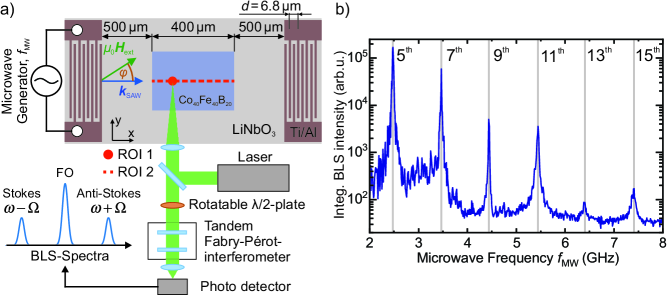
In the first part of our investigation, we characterized the phonon-spectra excited by the IDT by varying the applied rf-frequency in the range of 2 to 8 GHz. The obtained BLS-spectra were integrated in BLS-frequency for each rf-frequency. The resulting phonon excitation spectrum of the IDT is shown in Fig. 1 b). Excitation peaks arise periodically at frequencies , fulfilling the condition of constructive interference
| (1) |
where denotes the periodicity of the IDT. In Fig. 1 b) the lowest frequency peak corresponds to the 5th harmonic order of the IDT at GHz.
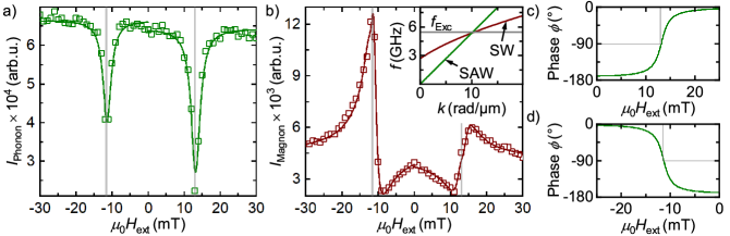
To investigate the magnetic field-dependent coupling of phonons and magnons, the laser spot is positioned about 100 µm into the ferromagnetic layer at ”ROI 1”, as indicated in Fig. 1 a). We make use of the rotatable plate, which allows for tuning the relative sensitivity of our BLS setup to magnons or phonons [33]. We excited the SAW at a rf-frequency of 5.45 GHz (11th order) and microwave output power of +18 dBm. The sample was oriented so that the angle between the propagation direction of the SAW given by and the external magnetic field was about . We integrated the BLS-spectra in the range of -5.25 GHz to -5.925 GHz for both the phonon and the magnon polarization of the plate. The resulting intensities as a function of the external magnetic field are given in Fig. 2 for a) the phonon- and b) the magnon signal.
First, we discuss in panel a) the phonon signal. Here, dips in the BLS signal are observed at a positive magnetic field of mT and a negative field of mT. The concomitant reduction in phonon number is attributed to resonant magnon-phonon coupling at the triple crosspoint (see the inset in Fig. 2 b)) between the linear SAW dispersion relation (green), the SW dispersion relation (red), and the excitation frequency (grey). The magnon dispersion relation is calculated using the Kalinikos-Slavin-equation [38]
| (2) |
We used broadband ferromagnetic resonance spectroscopy (see supplementary material) to determine the g-factor , Gilbert damping parameter , saturation magnetization T, and anisotropy field mT of our CoFeB film. The small field shift between the positive and negative resonance magnetic field is attributed to an offset of the Hall probe rather than any SW nonreciprocity.
The different dip intensities for positive and negative magnetic fields are attributed to the helicity mismatch effect [23, 24]. When changing directions of the magnetic field, the helicity of the spin wave is inverted, while the helicity of the SAW remains the same, as it is determined by the SAWs propagation direction. The helicity mismatch effect gives rise to different coupling efficiencies on whether the helicities match (pos. field) or mismatch (neg. field), thus leading to different dip magnitudes [10].
We model the obtained phonon signal as follows. Following Ref. [39], we assume that the obtained phonon BLS intensity is proportional to the out-of-plane displacement
| (3) |
The displacement after a certain propagation distance becomes magnetic field dependent due to the absorption of SAW phonons by SW generation. We derive the absorption of SAW power by following the approach of Küß et al. [24] and make use of the correlation between the SAW power and the displacement . Thus, the expected BLS intensity can be written as
| (4) |
where is the BLS intensity obtained from the SAW at the launching IDT, is a constant that quantifies the SAW-SW conversion efficiency and is the diagonal component of the magnetic susceptibility tensor . In this simple model, the SAW-SW helicity mismatch effect is phenomenologically taken into account by using different for and . We derive by solving the Landau-Lifshitz-Gilbert-equation (see supplementary material) and fit Eq. (4) to the data in Fig. 2 a) with fitting parameters and . As can be seen in Fig. 2 a), good agreement between the BLS-intensity and the fitting model can be obtained.
Next, we consider the obtained BLS signal measured at optimized magnon detection efficiency by rotating the plate correspondingly. Since the number of phonons is always significantly higher than the number of newly excited magnons, the fraction of the unfiltered phonon signal cannot be neglected and has to be taken into account. We observe a peak-dip-like behavior, as can be seen in Fig. 2 b), which we explain as follows: On resonance, phonons are annihilated, and magnons are generated. Because of the coherency of this process, the photons inelastically scattering off these magnons and phonons can interfere with each other. When sweeping through the resonance field, the phase relation between magnons and phonons changes, as detailed below, so that the interference is destructive/constructive depending on the magnetic field. This leads to a Fano-resonance-like lineshape [35].
To describe the obtained signal, we start by writing the BLS intensity as
| (5) |
with and representing the detection efficiency of the phononic and the magnonic signal at the given position of the plate, the dynamic out-of-plane magnetization component of the SW and the displacement due to the SAW. For the dynamic magnetization component and the displacement we make the generalized wave-like Ansatz
| (6) | ||||
| (7) |
where and are the magnetic field and spatially dependent amplitudes of the displacement and the dynamic magnetization. We also include the phase shift between the SAW driven dynamic magnetization and the SAW itself, similar to the classical driven harmonic oscillator, where a phase shift of is expected at resonance. The displacement can be derived as previously from the SAW power in Eq. (4).
The magnetic component is derived by the locally absorbed SAW power as due to the high Gilbert damping in the system, only the locally excited magnons contribute to the BLS signal, as will be discussed in more detail later on. By assuming that the SW power is proportional to the dynamic out-of-plane magnetization component and the locally absorbed SAW power flows into the spin wave system, we obtain
| (8) |
with the driving field generated by the SAW. As the amplitude of the SAW decreases with increasing propagation length, so does the driving field. In turn, the driving field can again be derived using the displacement by . Thus, we obtain for the expected BLS intensity by only taking the real part of Eq. (5) and neglecting higher order terms that are not linear in
| (9) |
Here, and are again constant prefactors included for simplification and to combine other constant prefactors. We use Eq. (9) to fit the data in Fig. 2 b). As can be seen, we achieve good agreement between the obtained experimental data and our model. In Fig. 2 c) and d) the resulting phase shift between the SAW and the SW is shown, becoming -90∘ at the resonant coupling field in agreement with the expectation for a driven harmonic oscillator. Thus, our experimental data provides evidence for a well-defined phase relation and thus coherency between the annihilated phonons and generated magnons.
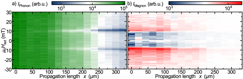
Next, we map the magnetoelastic coupling as a function of the external magnetic field and the propagation distance of the SAW. For this, we use an excitation frequency of 2.48 GHz at an excitation power of +18 dBm and exploit the second-order harmonic generation [40, 41, 32] of the 10th order IDT resonance at 5 GHz to investigate the space-dependent coupling. The magnetic field was aligned as before (), however, now a linescan measurement was performed, as indicated by the red dashed line labeled ”ROI 2” in Fig. 1 a). Again, we measured using both phonon and magnon polarization and integrated the resulting BLS-spectra in BLS frequency. The results are presented in Fig. 3, in panel a) for the obtained phonon signal and in b) the magnon signal, as a function of the applied magnetic field and the propagation length . Here, the scaled intensity on phonon-polarization at 30 mT is subtracted in order to remove the unfiltered phononic signal.
First, we discuss the obtained phonon signal. Here, two dips of different magnitudes start to form with increasing propagation length over the ferromagnetic layer. The magnetic fields at which the dips occur again correspond to the triple crosspoint between the excitation frequency and the dispersion relations of the SAW and the SW, as discussed before. The magnetic field dependence of the phonon signal becomes more pronounced with increased SAW propagation because of the progressive SAW absorption during its propagation in the CoFeB film. This finding supports the previously observed dependence of the electrically detected magnetoelastic interaction on the length of the magnetic film [25].
We now turn to the magnon signal shown in Fig. 3 b), where the highest excitation of magnons is found at the beginning of the ferromagnetic layer. Due to the considerably large Gilbert damping in the CoFeB film, magnons have a very low lifetime, leading to a short decay length of only about 1.81 µm at GHz and mT in Damon-Eshbach geometry (see supplementary material), thus vanishing almost instantly. Consequently, the magnon population does not build up with increasing propagation length and only locally excited SWs by the SAW are detected. Since the phonon density is highest at the start of the ferromagnetic layer, the highest excitation of magnons is found here, while fewer magnons are exited with increasing propagation length.
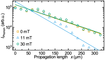
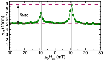
The coupling of the phonon to the magnon system opens a loss channel for the propagating SAW phonons. From the previously obtained data, we now determine the magnetic field dependency of the SAW amplitude decay rate. We obtain an exponential decrease in SAW amplitude with propagation distance which is characterized by the effective damping parameter , which we derive from the BLS-intensity by fitting
| (10) |
The factor results from the fact that the BLS intensity is proportional to the SAW intensity, which is again proportional to the squared SAW amplitude. We determine the effective damping by plotting the BLS-intensity as a function of the propagation length for each magnetic field in logarithmic representation as illustrated in Fig. 4. The obtained effective damping rates are shown in Fig. 5. The decay rate increases at the resonant coupling field with different magnitudes, indicating a non-reciprocal SAW-SW coupling [10], by 74 % at +11 mT and 41 % at -9 mT in comparison to off-resonant fields.
In summary, we demonstrated spatially resolved coherent interaction between phonons and magnons by micro-focused Brillouin light scattering experiments. By exploiting the shift in polarization of light scattered by magnons, we selectively detected the excitation of magnons and the absorption of phonons as a function of the applied magnetic field. We found that magnon and phonon signals interfere, demonstrating their coherence. By taking the coherent phase relation between SAW and SW into consideration, we formulated a phenomenological model for the expected BLS intensity, that we used to fit our data. Our spatially resolved data shows that the SAW-SW interaction does not result in increased SW propagation length [31]. This finding as well as the interference of phonons and magnons need to be considered for potential applications that rely on magnetoacoustically generated magnons or magnon-controlled phonon propagation.
Acknowledgements.
This work was funded by the Deutsche Forschungsgemeinschaft (DFG, German Research Foundation) – project number 492421737, the DFG TRR 173 - 268565370 (project B01) and by the European Union within the HORIZON-CL4- 2021-DIGITAL-EMERGING-01 Grant No. 101070536 M&MEMS.References
- Campbell, C. K. [1998] Campbell, C. K., Surface Acoustic Wave Devices for Mobile and Wireless Communications (Applications of Modern Acoustics, Academic Press, San Diego, CA, 1998, 1998).
- Länge, K. and Rapp, B.E. and Rapp, M. [2008] Länge, K. and Rapp, B.E. and Rapp, M., Anal. Bioanal. Chem. 391, 1509 (2008).
- Franke, T. and Abate, A.R. and Weitz, D.A. and Wixforth, A. [2009] Franke, T. and Abate, A.R. and Weitz, D.A. and Wixforth, A., Lab Chip 9, 2625 (2009).
- Lomonosov, A. M. and Hess, P. [2007] Lomonosov, A. M. and Hess, P., Phys. Rev. Lett. 89, 095501 (2007).
- Viktorov, I. A. [1967] Viktorov, I. A., Rayleigh and Lamb Waves: Physical Theory and Applications (Springer New York, NY, Plenum Press, New York, 1967, 1967).
- Hashimoto, K.-Y. [2000] Hashimoto, K.-Y., Surface Acoustic Wave Devices in Telecommunications: Modeling and Simulation (Springer-Verlag, Berlin, Heidelberg, 2000).
- Paschke, B. and Wixforth and A. and Denysenko, D. and Volkmer, D. [2017] Paschke, B. and Wixforth and A. and Denysenko, D. and Volkmer, D., ACS Sens. 2, 740 (2017).
- Ekström, Maria K. and Aref, Thomas and Runeson, Johan and Björck, Johan and Boström, Isac and Delsing, Per [2017] Ekström, Maria K. and Aref, Thomas and Runeson, Johan and Björck, Johan and Boström, Isac and Delsing, Per, Appl. Phys. Lett. 110, 073105 (2017).
- Yang, Wei-Gang and Schmidt, Holger [2021] Yang, Wei-Gang and Schmidt, Holger, Appl. Phys. Rev. 8, 021304 (2021).
- Küß, Matthias and Albrecht, Manfred and Weiler, Mathias [2022] Küß, Matthias and Albrecht, Manfred and Weiler, Mathias, Frontiers in Physics 10, 981257 (2022).
- Li, W. and Buford, B.. and Jander, A. and Dhagat, P. [2014] Li, W. and Buford, B.. and Jander, A. and Dhagat, P., J. Appl. Phys. 115, 17E307 (2014).
- Thevenard, L. and Camara, I. S. and Majrab, S. and Bernard, M. and Rovillain, P. and Lemaître, A. and Gourdon, C. and Duquesne, J.-Y. [2016] Thevenard, L. and Camara, I. S. and Majrab, S. and Bernard, M. and Rovillain, P. and Lemaître, A. and Gourdon, C. and Duquesne, J.-Y., Phys. Rev. B 93, 134430 (2016).
- Tomoyuki, Y. and Satoshi, S. and Bivas, R. and Shinichiro, S. and Naoki, O. and Shinya, K. and Yoshichika, O. [2020] Tomoyuki, Y. and Satoshi, S. and Bivas, R. and Shinichiro, S. and Naoki, O. and Shinya, K. and Yoshichika, O., Nature Nanotechnology 15, 361 (2020).
- Chen, Ruyi and Chen, Chong and Han, Lei and Liu, Peisen and Su, Rongxuan and Zhu, Wenxuan and Zhou, Yongjian and Pan, Feng and Song, Cheng [2023] Chen, Ruyi and Chen, Chong and Han, Lei and Liu, Peisen and Su, Rongxuan and Zhu, Wenxuan and Zhou, Yongjian and Pan, Feng and Song, Cheng, Nat Commun 14, 4427 (2023).
- Zhang, W. and Maldonado, P. and Jin, Z. and Seifert, T. and Arabski, J. and Schmerber, G. and Beaurepaire, E. and Bonn, M. and Kampfrath, T. and Oppeneer, P.M. and Turchinovich, D. [2020] Zhang, W. and Maldonado, P. and Jin, Z. and Seifert, T. and Arabski, J. and Schmerber, G. and Beaurepaire, E. and Bonn, M. and Kampfrath, T. and Oppeneer, P.M. and Turchinovich, D., Nature Communication 11, 4247 (2020).
- Rovillain, P. and Duquesne, J. Y. and Christienne, L. and Eddrief, M. and Pini, M. G. and Rettori, A. and Tacchi, S. and Marangolo, M. [2022] Rovillain, P. and Duquesne, J. Y. and Christienne, L. and Eddrief, M. and Pini, M. G. and Rettori, A. and Tacchi, S. and Marangolo, M., Phys. Rev. Appl. 18, 064043 (2022).
- Dreher, L. and Weiler, M. and Pernpeintner, M. and Huebl, H. and Gross, R. and Brandt, M. and Goennenwein, S. [2012] Dreher, L. and Weiler, M. and Pernpeintner, M. and Huebl, H. and Gross, R. and Brandt, M. and Goennenwein, S., Phys. Rev. B Condens. Matter 86, 5 (2012).
- Weiler, M. and Dreher, L. and Heeg, C. and Huebl, H. and Gross, R. and Brandt, M.S. and Goennenwein, S.T.B. [2011] Weiler, M. and Dreher, L. and Heeg, C. and Huebl, H. and Gross, R. and Brandt, M.S. and Goennenwein, S.T.B., Phys. Rev. Lett. 106, 117601 (2011).
- Geilen, M. and Verba, R. and Nicoloiu, A. and Narducci, D. and Dinescu, A. Ender, M. and Mohseni, M. and Ciubotaru, F. and Weiler, M. and Müller, A. and Hillebrands, B. and Adelmann, C. and Pirro, P. [2022] Geilen, M. and Verba, R. and Nicoloiu, A. and Narducci, D. and Dinescu, A. Ender, M. and Mohseni, M. and Ciubotaru, F. and Weiler, M. and Müller, A. and Hillebrands, B. and Adelmann, C. and Pirro, P., Parametric excitation and instabilities of spin waves driven by surface acoustic waves (2022), arXiv:2201.04033 .
- Shah, Piyush J. and Bas, Derek A. and Hamadeh, Abbass and Wolf, Michael and Franson, Andrew and Newburger, Michael and Pirro, Philipp and Weiler, Mathias and Page, Michael R. [2023] Shah, Piyush J. and Bas, Derek A. and Hamadeh, Abbass and Wolf, Michael and Franson, Andrew and Newburger, Michael and Pirro, Philipp and Weiler, Mathias and Page, Michael R., Adv. Electron. Mater. 9, 2300524 (2023).
- Weiler, M. and Huebl, H. and Goerg, F. S. and Czeschka, F. D. and Gross, R. and Goennenwein, S. T. B. [2012] Weiler, M. and Huebl, H. and Goerg, F. S. and Czeschka, F. D. and Gross, R. and Goennenwein, S. T. B., Phys. Rev. Lett. 108, 176601 (2012).
- Kawada, Takuya and Kawaguchi, Masashi and Funato, Takumi and Kohno, Hiroshi and Hayashi, Masamitsu [2021] Kawada, Takuya and Kawaguchi, Masashi and Funato, Takumi and Kohno, Hiroshi and Hayashi, Masamitsu, Sci. Adv. 7, eabd9697 (2021).
- Xu, M. and Yamamoto, K. and Puebla, J. and Baumgaertl, K. and Rana, B. and Miura, M. and Takahashi, H. and Grundler, D. and Maekawa, S. and Otani, Y. [2020] Xu, M. and Yamamoto, K. and Puebla, J. and Baumgaertl, K. and Rana, B. and Miura, M. and Takahashi, H. and Grundler, D. and Maekawa, S. and Otani, Y., Sci. Adv. 6 (2020).
- Küß, M. and Heigl, M. and Flacke, L. and Hörner, A. and Weiler, M. and Albrecht, M. and Wixforth, A. [2020] Küß, M. and Heigl, M. and Flacke, L. and Hörner, A. and Weiler, M. and Albrecht, M. and Wixforth, A., Phys. Rev. Lett. 125, 217203 (2020).
- Küß, Matthias and Glamsch, Stephan and Kunz, Yannik and Hörner, Andreas and Weiler, Mathias and Albrecht, Manfred [2023] Küß, Matthias and Glamsch, Stephan and Kunz, Yannik and Hörner, Andreas and Weiler, Mathias and Albrecht, Manfred, ACS Appl. Electron. Mater. 5, 5103 (2023).
- Verba, R. and Lisenkov, I. and Krivorotov, I. and Tiberkevich, V. and Slavin, A. [2018] Verba, R. and Lisenkov, I. and Krivorotov, I. and Tiberkevich, V. and Slavin, A., Phys. Rev. Appl. 9, 064014 (2018).
- Liang, B. and Yuan, B. and Cheng, J.-C. [2009] Liang, B. and Yuan, B. and Cheng, J.-C., Phys. Rev. Lett. 103, 104301 (2009).
- Verba, R. and Bankowski, E.N. and Meitzler, T.J. and Tiberkevich, V. and Slavin, A. [2021] Verba, R. and Bankowski, E.N. and Meitzler, T.J. and Tiberkevich, V. and Slavin, A., Adv. Electron. Mater. 7, 2100263 (2021).
- Küß, M. and Heigl, M. and Flacke, L. and Hefele, A. and Hörner, A. and Weiler, M. and Albrecht, M. and Wixforth, A. [2021] Küß, M. and Heigl, M. and Flacke, L. and Hefele, A. and Hörner, A. and Weiler, M. and Albrecht, M. and Wixforth, A., Phys. Rev. Appl. 15, 034046 (2021).
- Zhao, Chenbo and Zhang, Zhizhi and Li, Yi and Zhang, Wei and Pearson, John E. and Divan, Ralu and Liu, Qingfang and Novosad, Valentine and Wang, Jianbo and Hoffmann, Axel [2021] Zhao, Chenbo and Zhang, Zhizhi and Li, Yi and Zhang, Wei and Pearson, John E. and Divan, Ralu and Liu, Qingfang and Novosad, Valentine and Wang, Jianbo and Hoffmann, Axel, Phys. Rev. Applied 15, 014052 (2021).
- Casals, Blai and Statuto, Nahuel and Foerster, Michael and Hernández-Mínguez, Alberto and Cichelero, Rafael and Manshausen, Peter and Mandziak, Ania and Aballe, Lucía and Hernàndez, Joan Manel and Macià, Ferran [2020] Casals, Blai and Statuto, Nahuel and Foerster, Michael and Hernández-Mínguez, Alberto and Cichelero, Rafael and Manshausen, Peter and Mandziak, Ania and Aballe, Lucía and Hernàndez, Joan Manel and Macià, Ferran, Phys. Rev. Lett. 124, 137202 (2020).
- Kraimia, M. and Kuszewski, P. and Duquesne, J.-Y. and Lemaître, A. and Margaillan, F. and Gourdon, C. and Thevenard, L. [2020] Kraimia, M. and Kuszewski, P. and Duquesne, J.-Y. and Lemaître, A. and Margaillan, F. and Gourdon, C. and Thevenard, L., Phys. Rev. B 101, 144425 (2020).
- Geilen, Moritz and Nicoloiu, Alexandra and Narducci, Daniele and Mohseni, Morteza and Bechberger, Moritz and Ender, Milan and Ciubotaru, Florin and Hillebrands, Burkard and Müller, Alexandru and Adelmann, Christoph and Pirro, Philipp [2022] Geilen, Moritz and Nicoloiu, Alexandra and Narducci, Daniele and Mohseni, Morteza and Bechberger, Moritz and Ender, Milan and Ciubotaru, Florin and Hillebrands, Burkard and Müller, Alexandru and Adelmann, Christoph and Pirro, Philipp, Appl. Phys. Lett. 120, 242404 (2022).
- Kargar, F. and Balandin, A.A. [2021] Kargar, F. and Balandin, A.A., Nature Photonics 15, 720 (2021).
- Fano, U. [1961] Fano, U., Phys. Rev. 124, 1866 (1961).
- Yong S Joe and Arkady M Satanin and Chang Sub Kim [2006] Yong S Joe and Arkady M Satanin and Chang Sub Kim, Physica Scripta 74, 259 (2006).
- Latcham, O. S. and Gusieva, Y. I. and Shytov, A. V. and Gorobets, O. Y. and Kruglyak, V. V. [2019] Latcham, O. S. and Gusieva, Y. I. and Shytov, A. V. and Gorobets, O. Y. and Kruglyak, V. V., Appl. Phys. Lett. 115, 082403 (2019).
- Kalinikos, B. A. and Slavin, A. N. [1986] Kalinikos, B. A. and Slavin, A. N., J. Phys. C: Solid State Phys. 19, 7013 (1986).
- Cardona, M. and Güntherodt [1982] Cardona, M. and Güntherodt, Light scattering in solids III, Vol. 8,6 (Springer-Verlag, Berlin, Heidelberg, 1982).
- Lean, E.G. and Tseng, C.C. and Powell, C.G. [1970] Lean, E.G. and Tseng, C.C. and Powell, C.G., J. Appl. Phys. 16, 32 (1970).
- Lean, E.G. and Tseng, C.C. [1970] Lean, E.G. and Tseng, C.C., J. Appl. Phys. 41, 3912 (1970).