[1]\fnmI-Kang \surLiu
[1]\orgdivSchool of Mathematics, Statistics and Physics, \orgnameNewcastle University, \orgaddress \cityNewcastle upon Tyne, \postcodeNE1 7RU, \stateTyne and Wear, \countryUnited Kingdom
Vortex depinning in a two-dimensional superfluid
Abstract
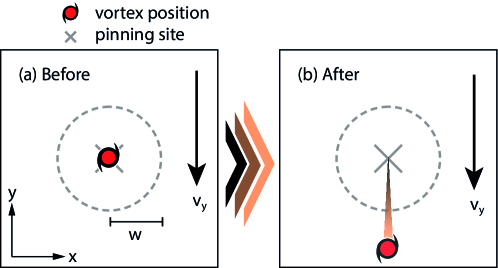
We employ the Gross–Pitaevskii theory to model a quantized vortex depinning from a small obstacle in a two-dimensional superfluid due to an imposed background superfluid flow. We find that, when the flow’s velocity exceeds a critical value, the vortex drifts orthogonally to the flow before subsequently moving parallel to it away from the pinning site. The motion of the vortex around the pinning site is also accompanied by an emission of a spiral-shaped sound pulse. Through simulations, we present a phase diagram of the critical flow velocity for vortex depinning together with an empirical formula that illustrates how the critical velocity increases with the height and width of the pinning site. By employing a variety of choices of initial and boundary conditions, we are able to obtain lower and upper bounds on the critical velocity and demonstrate the robustness of these results.
keywords:
vortex, superfluid1 Introduction
The interaction between topological defects and their environment is responsible for a host of fascinating phenomena in physical and biological systems. One of the most important examples thereof is the pinning of topological defects, e.g. rotating waves in cardiac muscles [1, 2, 3], vortices in active matter [4] and nematic defects in liquid crystals [5, 6]. In quantum fluids, such as superfluids and superconductors, the nucleation and motion of quantized vortices play crucial roles. For instance, in superfluid He-II, the presence of vortices can lead to dissipation of the superflow [7]. Additionally, vortices can be readily pinned to obstacles with a length scale comparable to the superfluid healing length [8], such as bumps in a superfluid container and defects in superconductors. Furthermore, vortex pinning results in a correction to the Berezinskii–Kosterlitz–Thouless transition in thin-film He-II [9, 10, 11], holding magnetic flux in type-II superconductors [12, 13, 14], an increase in critical counterflow velocity [5]. Vortex pinning can also be implemented in order to manipulate atomtronic devices [15, 16, 17].
Quantum fluids are also thought to be present in cosmological and astrophysical systems such as dark matter and neutron stars. In the ultra-light dark matter model [18, 19, 20, 21], vortices are found to be unstable in the central region of dark matter halos [22, 23, 24] but are associated with the granule size with a turbulence-like characteristics in the outer regions [25]. In the interior of a neutron star, both neutrons and protons can be in the superfluid phase [26]. The neutron fluid typically contains of order vortices, which can pin to the nuclear lattice in the star’s outer crust [27, 28] and to magnetic flux tubes in the star’s core [29, 30]. In this system, vortex pinning prevents the superfluid from spinning down at the same rate as the crust, thereby creating a rotational lag. It is believed that, when this lag reaches a critical value, the vortices depin and transfer angular momentum from the superfluid to the crust, resulting in a sudden increase in the observed rotational frequency known as a glitch. The exact process by which a glitch occurs is not fully understood but may involve an avalanche of millions of vortices that depin and thereby trigger further depinning [31]. Given the complexity of the mechanism underlying these spindown glitches, it is pertinent to first study the dynamics of a small number of vortices and thereby understand the conditions under which they depin, which is the aim of the present work.
From the perspective of a pinned vortex, the rotational lag in the neutron star crust manifests as an ambient superflow, which exerts a lateral Magnus force on the vortex [32]. Above a critical superfluid velocity, this force causes the vortex to depin, after which it moves with essentially the same velocity as the ambient flow. This critical velocity was first studied numerically by Schwarz [33] using the vortex filament method (in which a vortex is modelled as a one-dimensional line); in this model, the pinning site was a hemispherical ‘bump’ on the boundary of the superfluid. Subsequently, Tsubota and Maekawa [8] demonstrated that multiple vortices can be trapped on the same bump. More recently, Stockdale et al. [34] investigated a related problem — the scattering of a superfluid vortex by an obstacle. For an obstacle of large width, they found that the critical velocity for pinning could be predicted using the equation of motion for a vortex under the small-displacement approximation [35].
Despite this, the depinning process of a vortex subjected to a background superflow still lacks a detailed theoretical investigation. Thus, we carefully study the depinning dynamics of an initially pinned vortex due to the presence of a background superflow in a two-dimensional superfluid, as illustrated in Fig. 1. The superfluid system is modelled by the Gross–Pitaevskii equation with a phenomenological dissipation. The phase diagram of the critical depinning velocity is explored in terms of the height and width of the pinning potential, using an energetic argument to understand the transition between the pinned and free vortex states. A complementary set of simulations is also conducted in a different numerical setup with a different boundary condition to validate our finding.
This work is structured as follows. In Sec. 2 we describe our model and discuss the effects of dissipation on the vortex motion. We then proceed to address the numerical setup of simulating the dynamics of depinning and the results of these simulations in Sec. 3. Subsequently, in Sec. 4, we propose a phase diagram for the critical depinning velocity and an energy landscape for vortex depinning alongside a validation check of the depinning simulations employing quasiperiodic boundary conditions (QPBCs). Finally, we summarize and discuss our findings in Sec. 5.
2 Theoretical Formalism
2.1 Gross–Pitaevskii Theory
We model a two-dimensional superfluid using the damped Gross–Pitaevskii equation (dGPE) [36, 37, 38, 39, 40, 41],
| (1) |
where is the chemical potential and
| (2) |
The parameter describes the self-repulsion of the superfluid and is related to the -wave interaction strength [42]. For the pinning potential, , we assume a Gaussian profile [43, 44],
| (3) |
with height and width . The dimensionless parameter in equation (1) represents dissipation arising from the interaction between superfluid and normal components111Note that we work in the frame of the pinning site and that the normal component is assumed to be at rest in this frame.. In the context of Bose–Einstein condensates, is proportional to temperature and is usually considered to be spatially constant with a numerical value of [45, 46, 47]. However, for reasons described in Sec. 2.2, our model includes a spatially dependent that suppresses flows far from the pinning site.
As described later, we choose the value of in all of our simulations such that a constant density, , is maintained at large distances from the pinning site. The system then has a characteristic length scale given by the healing length, , and a characteristic time scale . The ratio of these determines the speed of sound in the superfluid, [42]. Provided that , dissipation only plays a role on a much longer time scale, [48, 49].
In this work, we theoretically investigate the critical depinning velocity of a vortex initially pinned by a pinning potential in a superfluid with a background flow . The width of the pinning potential, , is chosen to be of the same order as the healing length, , which is the relevant parameter regime for the neutron star crust. Unlike several previous works that assume a wide obstacle, we cannot use either the vortex filament or the Thomas–Fermi (TF) approximation in this regime. Instead, we use the dGPE model to determine the critical velocity. For later convenience, we introduce the following notation to represent different possible states of the system:
-
(i)
: a homogeneous density solution with a background flow;
-
(ii)
: a single vortex state subjected to a background flow;
-
(iii)
: a vortex-free state with a pinning site subjected to a background flow;
-
(iv)
: a pinned vortex state subjected to a background flow.
-
(v)
: a free (depinned) vortex state subjected to a background flow far away from the pinning site.
States (ii)–(v) cannot be fully described analytically and, instead, we study them numerically, focusing on the dynamics in Sec. 3 and the energetics in Sec. 4.2.
2.2 Numerical Setup
We solve Eq. (1) using a Fourier pseudospectral method and a 4th-order Runge–Kutta scheme with a time step of . The computational domain is a square box of width with grid points, thereby giving a grid spacing of . The pinning site, when present, is located at the centre of the box.
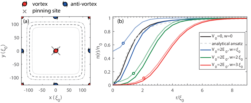
The use of Fourier transforms requires periodic boundary conditions in both and , and hence a vanishing net circulation around the boundary of the domain [50]. Although we are only interested in the dynamics of a single vortex, it is thus necessary to simulate an alternating lattice of vortices and anti-vortices as illustrated in Fig. 2 (a). Given the size of the domain, we expect the effect of these additional vortices to be small, and we minimise their effect further by introducing a sponge layer via a spatially dependent dissipation [40, 51, 52]. We adopt a smooth, rounded-rectangular sponge as plotted in Fig. 2 (a) by defining
| (4) |
where is the dissipation induced the interaction between superfluid and normal components. The strong dissipation set by at the boundaries of the domain damps any sound waves, thereby isolating the central vortex from its periodic neighbours. However, this dissipation also induces a transverse motion of the vortices near the edge of the domain, with a velocity [35, 17]. Fortunately, this transverse motion ends once the vortices reach the edge of the sponge layer. Thus, for a simulation domain large enough that the sponge layer is sufficiently distant from the central vortex, the effects of the edge vortices are marginal. Here we set , and .
Another consequence of our periodic boundary conditions is that the imposed superflow velocity, , must be an integer multiple of . This limits the precision with which the critical velocity can be determined but, given the size of the domain, this does not represent a significant limitation of our methodology.
2.3 Initialization
As noted earlier, we specify the value of the chemical potential in order to fix the (background) density to . The correct choice is not only dependent on and but also on the background superflow velocity . In the dGPE simulation, the dissipative term ultimately drives the system towards a state satisfying , and so we must choose the value of such that in this steady state the density is equal to far from the pinning site. To determine the appropriate value, we consider the grand-canonical energy of the system,
| (5) |
where is the domain area, is the -wave interaction strength and is the particle number in the domain. The damped Gross–Pitaevskii equation (1) can be expressed as , and the steady state corresponds to a minimum of the the functional . In the absence of any vortex or pinning site, we expect the steady state to be , and this is a minimum of Eq. (5) provided that
| (6) |
with a background energy . Therefore, is set to the value given by Eq. (6) in our simulations.
To initialise the system with a vortex (with or without a pinning site), we first set and imprint a phase winding by setting , where is the polar angle relative to the centre of the domain. The GPE is then solved in imaginary time (i.e. with in Eq. (1) replaced by -1), with , until the quantity
| (7) |
converges to within of . This converged state is then used as the initial condition for the dGPE. As mentioned earlier, because of the periodic boundary conditions this state actually features a lattice of vortices and anti-vortices but, for a sufficiently large domain, the central vortex is essentially independent of the others.
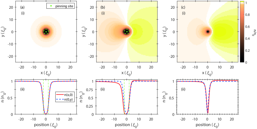
As examples of the solutions of Eq. (1), in Fig. 2 (b), we plot the density profiles of the free () and pinned () vortices (both represented by solid lines), as well as the vortex-free state subject to the pinning potential (, represented by dotted lines), for with different pinning widths . The vortex solutions show a density depletion with a width similar to the pinning site but it is also evident that they do not agree well with the Thomas-Fermi density,
| (8) | |||
| (9) |
as the radii within which the densities are strongly depleted is not in agreement with the TF radii, , which we have represented in Fig. 2 (b) as hollow circles. This suggests that the pinning potential height and width we have specified are too small for a vortex to be in the TF regime [34].
3 Depinning Dynamics
With the initial state prepared, we impose a background flow by introducing a phase gradient
| (10) |
where the value of is a multiple of as explained earlier. At the same time we update the value of to so that the system remains in a steady state far from the vortices and pinning site. The simulations are performed with three values of dissipation: , and . We find that the value of has very little effect on the dynamics, including the depinning process, except that after depinning the vortex drifts with respect to the ambient superflow by an amount proportional to . This transverse drift is expected for reasons mentioned in Sec. 2.2.
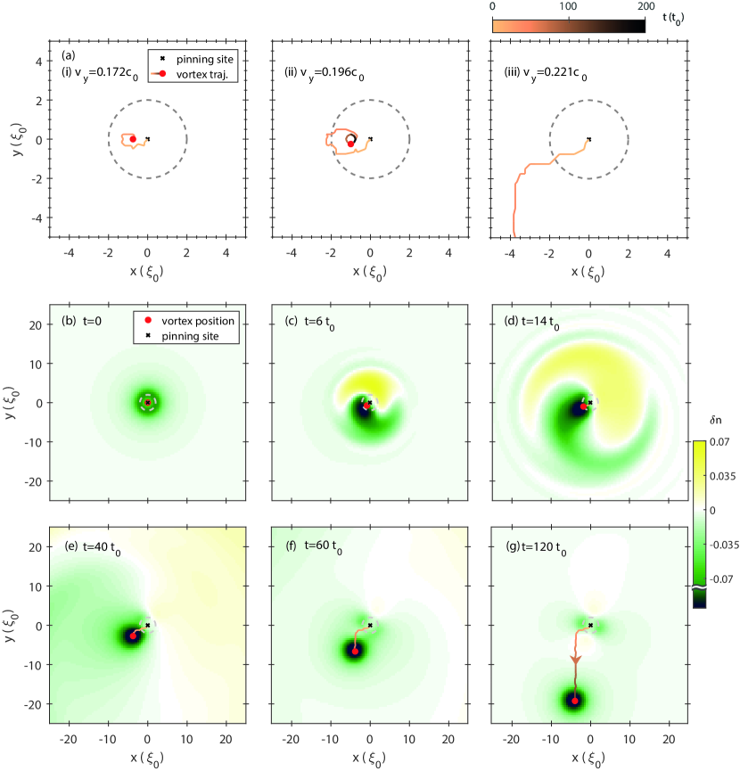
Three types of dynamics are found in our simulation: (1) if is sufficiently small, then the vortex is displaced a small distance from the centre of the pinning site, but remains pinned; (2) if exceeds a critical value, , the vortex depins and is carried away by the ambient superflow; and (3) if is a significant fraction of the sound speed, , additional vortices nucleate at the pinning site. However, the present work is not concerned with regime (3), which has been studied in detail by others, e.g. Refs. [43, 44]. Figure 3 (a) illustrates typical vortex trajectories in regimes (1) and (2) for and . The vortex position in the Figure is determined by locating the phase defect and density minimum in the wavefunction, after extrapolating to the sub-grid level, and the trajectory is subsequently tracked by linking timeframes using the Hungarian algorithm. In Fig. 3 the orange-black colour transition of the trajectories tracks the evolution of the vortex position from to . It is evident that, in regime (1), the vortex follows a spiral trajectory and eventually reaches an equilibrium position to the left of the pinning site centre. In this new equilibrium, the pinning force balances the Magnus force [32, 35]. The maximum spiral radius increases with , as shown in Fig. 3 (a) (i) and (ii) for and respectively. Conversely, if the system is in regime (2); the vortex initially follows a similar trajectory but moves far enough from the pinning site centre that it escapes and ultimately drifts with the ambient superflow.
In both regimes (1) and (2) the motion of the vortex excites sound waves that carry energy away from the vortex. To illustrate this, in Fig. 3 (b) – (g) we plot the density fluctuation , where is the density in the absence of a vortex or flow, together with the vortex trajectory for , , , , and . In these plots, the vortex location is marked by the red circle and the orange-black line is the trajectory up to time . Similarly to the case of a vortex in a stirred condensate [53], while the vortex remains close to the pinning site the sound waves form a dipolar pattern that spirals out from the vortex. For comparison, we have also performed a simulation with the same parameters but without a vortex; in that regime, sound waves are produced with a circular pattern while the density perturbations are smaller in magnitude by a factor of about 2.
The emission of sound waves becomes negligible in the later time dynamics whether the vortex remains pinned or depins, and those emitted at early times rapidly dissipate within the sponge layer around the domain boundary. We note that, as shown in Fig. 3 (g), density perturbations persist around the pinning site even after the vortex has depinned. This reflects the effect of the ambient flow on the pinning site. Furthermore, as mentioned earlier, at sufficiently high flow velocities vortices are nucleated in the pinning potential [43, 44]. If the pinning potential is too high () or too wide () then we find that this regime is reached before the superflow velocity reaches the critical depinning velocity . In this regime the depinning process is complicated by the involvement of multiple vortex interactions [34] and, therefore, we only present data for pinning sites with smaller values of and .
4 Critical Depinning Velocity
4.1 Phase Diagram of the Depinning Velocity
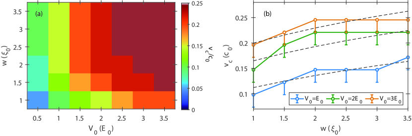
As illustrated in Sec. 3, if the imposed flow, , is not sufficient to depin the vortex then it generally settles to a new equilibrium position within a duration of . This new equilibrium is generally within a distance of the pinning site centre. In our results we therefore consider the vortex to be depinned if it is displaced by more than within a time of , and we define to be the smallest value of for which depinning occurs. (We recall that our periodic boundary conditions only allow us to increase in steps of . Therefore our results for may overestimate its true value by up to .) In Fig. 4 (a) we show the values of obtained for and . This Figure shows the results in the cases and , which are identical; the results for are nearly identical, except for the case and , where we find to be larger by . This indicates that dissipation plays a negligible role in determining the critical velocity in our simulations.
From dimensional analysis, the value of ought to depend only on , and . Thus, for sufficiently small , we ought therefore to be able to fit our results to a function of the form . Before performing this fitting, we first briefly review earlier work concerning the form of the function . Stockdale et al. [34] used the equation of motion of a vortex under the small-displacement approximation [35], in the absence of dissipation, to investigate the pinning of a vortex in 2D with a circular top-hat barrier and a background flow. Making a Thomas–Fermi approximation for the density, they found that the vortex remains pinned if its equation of motion has a fixed point within the pinning site. In terms of our notation, the critical depinning velocity is then given by
| (11) |
where is the radius of the obstacle and is a phenomenological screening parameter of order . This result is only valid in the regime where and , however, which is not the regime of interest of the present work.
Earlier, Schwarz [33] used a vortex-filament model to simulate a vortex pinned to a hemispherical bump on the boundary of the domain. Here the critical depinning velocity was found to be
| (12) |
where is the radius of the obstacle and is the channel width of the superfluid container. Again, this result assumes and is intrinsically three-dimensional, and thus it is not directly applicable to our results.
Motivated by the above literature, and by the results in Fig. 4 (a), we seek a fit of the critical velocity to the form
| (13) |
where the parameters , and are assumed to be constant. Applying a least-squares fit to our data, we find
| (14) |
and for these coefficients the empirical formula predicts to within across our data set. In Fig. 4 (b) we plot as a function of for three values of , alongside our empirical formula.
4.2 Vortex Energy
In our simulations, energy is injected into the system by a sudden increase in the superflow from to . Part of this energy is converted into sound, and part may be used to depin the vortex. In general we would not expect the vortex to depin unless doing so reduces the overall energy in the system, and this fact can potentially be used to determine a lower bound on the critical velocity . Specifically, we seek to determine the value of for which the energy of a pinned vortex state exceeds that of an depinned vortex state. This energy can be defined as the energy cost to create the targeted state from a relevant reference state, which is conventionally chosen to be the ground state of the free energy function given by Eq. (5). For a free vortex state, , this is equivalent to the energy of a vortex state, subtracted by the vortex-free state energy, for a fixed number of superfluid atoms in a domain of area [54]. This complexity can be reduced by carrying out the calculation of the grand-canonical energy, Eq. (5), at a fixed chemical potential instead [42, 55]. In this case,
| (15) |
where represents the target state and is a suitable reference groundstate. According to the aforementioned energetic argument, a lower bound on can be determined by finding the value of above which the excess energy of a free vortex state far away from the pinning site, , is less than that of a pinned vortex, i.e.,
| (16) |
for . Here we specifically consider to be the area of a circular disk with radius , giving , and a vortex or pinning potential is positioned at the centre of the disk.
The creation energy of a free vortex can be estimated by the required energy added into a homogeneous superfluid, namely, with . The wavefunction of a free -charged vortex can be well approximated by an analytical profile [42, 54, 56],
| (17) |
where and is the radius of the vortex core. In the limit , the leading order terms give
| (18) |
and the minimization of with respect to gives 222From the Laplacian in cylindrical coordinates, , which may not be fully satisfied by this ansatz for .. This solution, represented in Fig. 2 (b) as a grey dashed line, agrees well with the corresponding numerical solution represented by the black unbroken line in the same figure. The free vortex energy can then be simplified as333In Ref. [42, 54, 56], it is shown via the relation that Eq. (18) can be rewritten as ,
| (19) |
For a singly-charged vortex, , the numerical result of agrees well with this prediction as demonstrated in Fig. 6. We note, however, that the -dependent terms in this analytical calculation cancel each other out and cannot provide a further prediction of . Furthermore, we reiterate that due to the healing length-sized pinning potential, the Thomas–Fermi density profile is not a particularly good approximation for the vortex state as shown in Fig. 2 (b).
To evaluate the vortex energy with a background flow, we numerically obtain and by propagating an initial trial vortex state, Eq. (17), in imaginary time with . When the flow amplitude is small, we found that can reduce to less than quickly. In contrast for large , the convergence is much slower and the central and boundary-induced vortices would annihilate as . In addition, when is large enough the vortex is detached from the pinning potential. Hence, we reduce the numerical tolerance so that imaginary time propagation is run until . We note, due to this relaxation of numerical tolerance, this state might be merely metastable. Indeed, even for it is possible to find pinned vortex states and some of the vortices may remain pinned after we move to real-time evolution.
In Fig. 5, we illustrate the density profiles of for and with and as well as that of with for the sake of comparison. When the superflow velocity is nonzero, the density becomes locally axially asymmetric about the vortex and pinning site for both and . The latter case can be observed in the plot of in Fig. 3 (g) where a quadrupolar density fluctuation profile is evident 444We remind the reader that, in our numerical method, is determined by Eq. (6).. The combination of the background and vortex flows and the interaction with the pinning potential locally affects the density and has a maximum influence along the direction orthogonal to the flow. Therefore this effect is minimized parallel to the flow in , as shown in Fig. 5 (b) and (c), where it is apparent that remains almost symmetric along the axis. We note that during the propagation of Eq. (1) in real time over timescales comparable to the characteristic relaxation timescale, , the stability of these vortex states is ambiguous even when . This indicates that a depinning process requires additional energy or instabilities compared to those considered here.
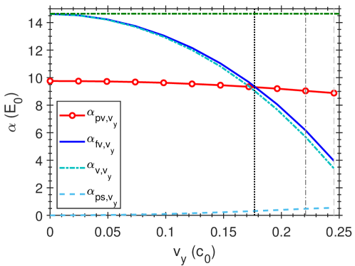
We have also computed from the numerical simulations for a domain given by a disk, centred on the pinning site, with an area where . In Fig. 6, we show the numerical results of and together with and for and as an example. Here, one can see that the pinned vortex energy is approximately constant while the free vortex energy shows a stronger dependence on and decreases monotonically as a function of . We also note that the value of agrees with the analytical calculation presented earlier. Given that and , there exists a value of where and Eq. (16) is satisfied. Above this velocity, we expect it is energetically favourable for the vortex to depin, with the black vertical dotted line in Fig. 6 showing the estimated critical velocity for the set of parameters. However, what we observe is that the value of based on energetic considerations alone is found to be less than in the dGPE simulations of Sec. 3 by roughly (note the grey vertical dot-dashed line in the figure). Such caveats notwithstanding, we argue that this estimate of based on purely energetic arguments offers a robust order of magnitude estimate. The small difference between the two values points to additional physics playing a role in the process of depinning, which could be the focus of future studies.
4.3 Quasiadiabatic Advective Acceleration
For reasons explained in Sec. 2.2, the use of periodic boundary conditions has consequences for our numerical simulations. For instance, as demonstrated in Fig. 2 (a), the requirement that be circulation-free inside the computational cell results in a vortex lattice of alternating circulations when a vortex is imprinted during the imaginary-time propagation of Eq. (1). Crucially, the periodicity of also restricts the allowed values for the imposed flow velocity . To test the robustness of our results, we have therefore also taken a complementary approach, using a different numerical scheme to slowly accelerate the imposed flow from zero to a desired value, after which its value is held fixed. To do so, we first perform a Galilean transformation of the Gross–Pitaevskii equation into the frame moving with velocity , hereafter referred to as the advective Gross–Pitaevskii equation (aGPE):
| (20) |
We solve this equation together with quasiperiodic boundary conditions (QPBCs),
| (21) | |||
| (22) |
that account for the phase winding arising from a single vortex within the domain. Initially introduced in the context of superfluid vortices in Ref. [57] and subsequently applied in Refs. [58, 59, 60], QPBCs have proven to be advantageous for the study of vortex configurations of nonzero net circulation in a homogeneously uniform background fluid. Because the velocity is slowly increased in this new setup, we anticipate that little sound will be produced, and therefore we do not include any dissipation in the model. It is for this reason that we refer to this setup as “quasiadiabatic”, in contrast to the instantaneous acceleration of the flow considered in Sec. 3.
Initially, we obtain the stationary state with a vortex at the origin by imprinting a superfluid phase 555 is the Jacobi theta function of with nome , whose argument is a suitable phase profile for an incompressible vortex in our chosen (Landau) gauge [59]. [61, 62]
| (23) |
and solve the aGPE in imaginary time to find the ground state. Subsequently, the dynamics of this vortex are simulated by propagating Eq. (20) forward in time with a slow acceleration of the advection as given by
| (24) |
where the final advection index sets up the advective flow after the acceleration, and the same spatial grids and timestep used are the same as those in Sec. 4.1. The advective flow velocity takes to reach the final value according to Eq. (24), a duration we believe to be sufficient for the vortex to adjust adiabatically to a finite advection. Subsequently, the aGPE is propagated up to to allow time for the vortex to depin, à la Fig. 3. This numerical setup is designed to inject as little energy as possible into the system during the acceleration of the flow, and therefore we expect the critical depinning velocity, , that we obtain to be an upper bound for in any other numerical setup.
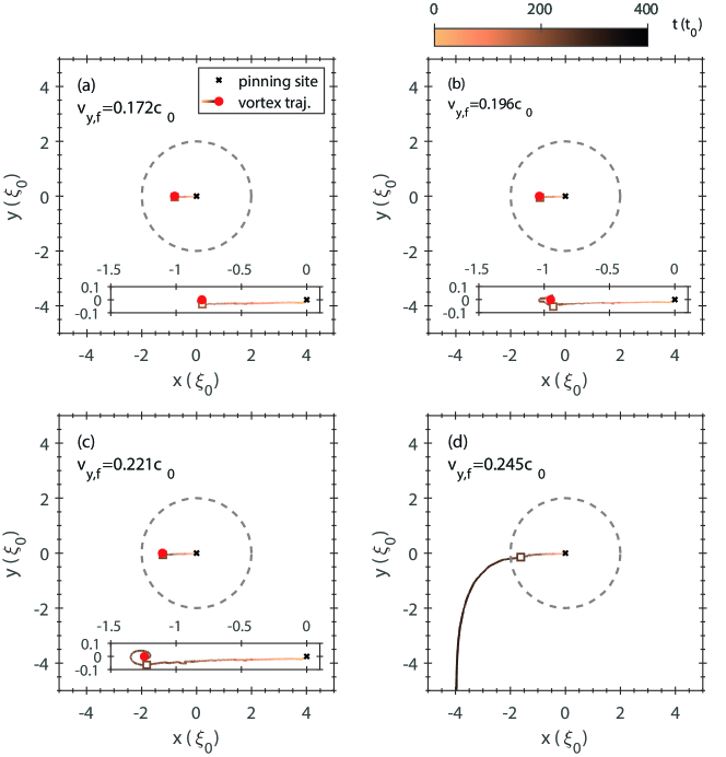
Throughout the quasiadiabatic advective simulations, we use a plaquette-based subgrid interpolation method [63] to locate the vortex as precisely as possible and track the evolution of its position. In Fig. 7, the vortex trajectories of the aGPE simulation for and with are shown. From this, we identify the lowest that dislodges the initially pinned vortex as the critical velocity. Similar to the simulations presented in Sec. 3, we see that the vortex initially always drifts to the left of the pinning site centre as a consequence of the Magnus effect. Once reaches its final value, , if this value is sufficiently small then the vortex quickly inspirals to a new equilibrium position; this final equilibrium position is comparable to that in Sec. 3. However, if exceeds a critical velocity, , then the vortex is able to escape the pinning potential, as illustrated in Fig. 7 (d). With this quasiadiabatic setup, we still observe the emission of a spiral pulse of sound waves, but their amplitude is about an order of magnitude smaller than in the instantaneously imposed-flow simulations. The critical velocity obtained via this approach is comparable to that found in Sec. 3, but somewhat larger, as illustrated by the grey dashed vertical line in Fig. 6.
5 Conclusion
In these proceedings, we have numerically simulated how an imposed superflow can detach a vortex that is initially pinned to an obstacle of size comparable to the superfluid healing length. We find that, below a critical velocity, the Magnus force causes the vortex to drift laterally with respect to the imposed flow before ultimately spiralling into a new equilibrium position. The motion of the vortex is responsible for the emission of a spiral of sound which contributes to the loss of energy and stabilization of the vortex. If the imposed superflow exceeds a critical value, then the vortex escapes the pinning region and is carried away by this superflow. The critical depinning velocities obtained from dGPE simulations are presented in a phase diagram as a function of the height and width of the Gaussian potential which defines the pinning site. Inspired by theoretical predictions existing in the literature [34, 33], we propose a new empirical formula for the critical depinning velocity which is in quantitative agreement with our numerical findings. When the pinning potential is sufficiently high and wide, vortices can be nucleated in the pinning potential by the imposed flow.
We then provide an energetic argument for a vortex transitioning from a pinned state to a free (depinned) state by evaluating the vortex nucleation energy under different conditions. The free vortex energy can be analytically evaluated by an axially symmetric trial solution, but the flow dependence in energy is not characterized in this Ansatz. Therefore we utilize the imaginary-time propagation method to search for pinned vortex states which are nonexistent when the flow is too rapid. The pinned states are asymmetric, not only in the off-axis location of the vortex in the pinning potential but also a flow-induced asymmetry of the density which is nonetheless small in magnitude. We find that these solutions are not always stationary over long periods of imaginary time propagation but still provide sensible estimations of the pinned states, suggesting that it might be prudent to consider improved numerical methods in future investigations [64, 55]. Proceeding to examine the energy landscape of free and pinned vortices we observe that the energy of a vortex decreases monotonically as a function of superflow velocity. However, while the energy of a pinned vortex is lower than that of a free vortex for low velocities, its rate of decrease as a function of the superflow velocity is also correspondingly lower. This results in a crossover superfluid velocity above which free vortices are energetically preferable, a velocity that is comparable to but generally lower than the critical velocities found by direct dGPE simulations with an imposed superflow.
Lastly, we verify our finding with a set of complementary simulations where quasiperiodic boundary conditions are employed to describe a vortex subject to a pinning site being accelerated almost adiabatically to the desired final value of the superflow velocity. These studies, conducted in the reference frame advected with the superflow, provide slightly higher estimates for the critical velocity. Together with our analysis of the energy landscape of pinned and free vortices, this suggests that vortex depinning requires additional energy or instabilities aside from effects arising at the boundaries.
In conclusion, this work develops new insights into the depinning dynamics in a pure 2D superfluid system from a narrow obstacle that are amenable to experimental investigations of superfluids and applicable to theoretical studies of neutron stars. This opens the door to combining studies of the influence of a background superflow with that of ambient sound waves in depinning a vortex from a pinning site. For instance, it has been proposed that the sound waves emitted by a moving vortex around the pinning site can induce the depinning of vortices in its vicinity [65]. Thus we believe that a natural direction for research in this field would be the study of the vortex-vortex and vortex-sound scattering processes in a system of multiple, initially pinned, vortices in the presence of superflow.
Acknowledgments
We thank Andrew Groszek and Thomas Bland for their helpful discussions. SBP acknowledges fruitful discussions with Marco Antonelli and Ryan Doran regarding the use of quasiperiodic boundary conditions.
Declarations
IKL and SBP conducted the simulations and contributed the majority of the manuscript with a vortex detection algorithm provided by AWB. The concepts of this work were framed by CFB, AWB and TSW with significant physics input, suggestions and guidance regarding the analysis. IKL, AWB, CFB and TSW acknowledge the funding from Science and Technology Facilities Council grant ST/W001020/1, and SBP and AWB acknowledge the support of the Leverhulme Trust through the Research Project Grant RPG-2021-108. The numerical simulations in this investigation were conducted using the Rocket High Performance Computing facility at Newcastle University.
For the purpose of Open Access, the author has applied a CC BY public copyright licence to any Author Accepted Manuscript (AAM) version arising from this submission.
References
- \bibcommenthead
- Davidenko et al. [1992] Davidenko, J.M., Pertsov, A.V., Salomonsz, R., Baxter, W., Jalife, J.: Stationary and drifting spiral waves of excitation in isolated cardiac muscle. Nature 355(6358), 349–351 (1992) https://doi.org/10.1038/355349a0
- Pumir and Krinsky [1999] Pumir, A., Krinsky, V.: Unpinning of a rotating wave in cardiac muscle by an electric field. Journal of Theoretical Biology 199(3), 311–319 (1999) https://doi.org/10.1006/jtbi.1999.0957
- Takagi [1991] Takagi, S.: Quantum Dynamics and Non-Inertial Frames of References. II: Harmonic Oscillators. Progress of Theoretical Physics 85(4), 723–742 (1991) https://doi.org/10.1143/ptp/85.4.723
- Pazó et al. [2004] Pazó, D., Kramer, L., Pumir, A., Kanani, S., Efimov, I., Krinsky, V.: Pinning force in active media. Phys. Rev. Lett. 93, 168303 (2004) https://doi.org/10.1103/PhysRevLett.93.168303
- Campbell et al. [2014] Campbell, M.G., Tasinkevych, M., Smalyukh, I.I.: Topological polymer dispersed liquid crystals with bulk nematic defect lines pinned to handlebody surfaces. Phys. Rev. Lett. 112, 197801 (2014) https://doi.org/10.1103/PhysRevLett.112.197801
- Nayek et al. [2012] Nayek, P., Jeong, H., Park, H.R., Kang, S.-W., Lee, S.H., Park, H.S., Lee, H.J., Kim, H.S.: Tailoring monodomain in blue phase liquid crystal by surface pinning effect. Applied Physics Express 5(5), 051701 (2012) https://doi.org/10.1143/APEX.5.051701
- Donnelly [1991] Donnelly, R.J.: Quantized Vortices in Helium II. Cambridge University Press, ??? (1991)
- Tsubota and Maekawa [1993] Tsubota, M., Maekawa, S.: Pinning and depinning of two quantized vortices in superfluid He4. Physical Review B 47(18), 12040–12050 (1993) https://doi.org/10.1103/PhysRevB.47.12040
- Hegde, S. G.; Glaberson [1980] Hegde, S. G.; Glaberson, W.I.: Pinning of Superfluid Vortices to Surfaces. Physical Review Letters 45(3), 190–193 (1980) https://doi.org/10.1103/PhysRevLett.45.190
- Ambegaokar et al. [1980] Ambegaokar, V., Halperin, B.I., Nelson, D.R., Siggia, E.D.: Dynamics of superfluid films. Phys. Rev. B 21, 1806–1826 (1980) https://doi.org/10.1103/PhysRevB.21.1806
- Adams and Glaberson [1987] Adams, P.W., Glaberson, W.I.: Vortex dynamics in superfluid helium films. Phys. Rev. B 35, 4633–4652 (1987) https://doi.org/%****␣main_v1.6_arxiv.tex␣Line␣700␣****10.1103/PhysRevB.35.4633
- Nelson and Vinokur [1993] Nelson, D.R., Vinokur, V.M.: Boson localization and correlated pinning of superconducting vortex arrays. Phys. Rev. B 48, 13060–13097 (1993) https://doi.org/10.1103/PhysRevB.48.13060
- Blatter, G; Feigel’man, M. V.; Geshkenbein, V. B.; Larkin, A. I.; Vinokur [1994] Blatter, G; Feigel’man, M. V.; Geshkenbein, V. B.; Larkin, A. I.; Vinokur, V.M.: Vortices in high-temperature superconductors. Reviews of Modern Physics 66(4), 1125 (1994) https://doi.org/10.1103/RevModPhys.66.1125
- Kwok et al. [2016] Kwok, W.-K., Welp, U., Glatz, A., Koshelev, A.E., Kihlstrom, K.J., Crabtree, G.W.: Vortices in high-performance high-temperature superconductors. Reports on Progress in Physics 79(11), 116501 (2016) https://doi.org/10.1088/0034-4885/79/11/116501
- Neely et al. [2013] Neely, T.W., Bradley, A.S., Samson, E.C., Rooney, S.J., Wright, E.M., Law, K.J.H., Carretero-González, R., Kevrekidis, P.G., Davis, M.J., Anderson, B.P.: Characteristics of two-dimensional quantum turbulence in a compressible superfluid. Phys. Rev. Lett. 111, 235301 (2013) https://doi.org/10.1103/PhysRevLett.111.235301
- Amico et al. [2021] Amico, L., et al.: Roadmap on Atomtronics: State of the art and perspective. AVS Quantum Sci. 3(3), 039201 (2021) https://doi.org/10.1116/5.0026178 arXiv:2008.04439 [cond-mat.quant-gas]
- Bland et al. [2022] Bland, T., Yatsuta, I.V., Edwards, M., Nikolaieva, Y.O., Oliinyk, A.O., Yakimenko, A.I., Proukakis, N.P.: Persistent current oscillations in a double-ring quantum gas. Physical Review Research 4(4), 1–11 (2022) https://doi.org/10.1103/PhysRevResearch.4.043171 arXiv:2204.14120
- Schive et al. [2014] Schive, H.-Y., Chiueh, T., Broadhurst, T.: Cosmic structure as the quantum interference of a coherent dark wave. Nature Physics 10(7), 496–499 (2014) https://doi.org/10.1038/nphys2996
- Marsh and Pop [2015] Marsh, D.J.E., Pop, A.-R.: Axion dark matter, solitons and the cusp–core problem. Monthly Notices of the Royal Astronomical Society 451(3), 2479–2492 (2015) https://doi.org/10.1093/mnras/stv1050
- Marsh [2016] Marsh, D.J.E.: Axion cosmology. Physics Reports 643, 1–79 (2016) https://doi.org/10.1016/j.physrep.2016.06.005 arXiv:1510.07633
- Ferreira [2021] Ferreira, E.G.M.: Ultra-Light Dark Matter. The Astronomy and Astrophysics Review 29, 7 (2021) https://doi.org/10.1007/s00159-021-00135-6
- Rindler-Daller and Shapiro [2012] Rindler-Daller, T., Shapiro, P.R.: Angular momentum and vortex formation in Bose-Einstein-condensed cold dark matter haloes. Monthly Notices of the Royal Astronomical Society 422(1), 135–161 (2012) https://doi.org/10.1111/j.1365-2966.2012.20588.x
- Dmitriev et al. [2021] Dmitriev, A.S., Levkov, D.G., Panin, A.G., Pushnaya, E.K., Tkachev, I.I.: Instability of rotating Bose stars. Physical Review D 104(2), 023504 (2021) https://doi.org/10.1103/PhysRevD.104.023504 arXiv:2104.00962
- Schobesberger et al. [2021] Schobesberger, S.O., Rindler-Daller, T., Shapiro, P.R.: Angular Momentum and the Absence of Vortices in the Cores of Fuzzy Dark Matter Haloes. Monthly Notices of the Royal Astronomical Society 505(1), 802–829 (2021) https://doi.org/10.1093/mnras/stab1153 arXiv:2101.04958
- Liu et al. [2023] Liu, I.-K., Proukakis, N.P., Rigopoulos, G.: Coherent and incoherent structures in fuzzy dark matter haloes. Monthly Notices of the Royal Astronomical Society 521(3), 3625–3647 (2023) https://doi.org/10.1093/mnras/stad591 arXiv:2211.02565
- Pethick et al. [2017] Pethick, C.J., Schäfer, T., Schwenk, A.: Bose-Einstein condensates in neutron stars. Universal Themes of Bose-Einstein Condensation, 573–592 (2017) https://doi.org/10.1017/9781316084366.031 arXiv:1507.05839
- Jones [2001] Jones, P.B.: First-principles point-defect calculations for solid neutron star matter. Monthly Notices of the Royal Astronomical Society 175, 167–175 (2001) https://doi.org/10.1046/j.1365-8711.2001.03990.x
- Donati and Pizzochero [2004] Donati, P., Pizzochero, P.M.: Fully consistent semi-classical treatment of vortex – nucleus interaction in rotating neutron stars. Nuclear Physics A 742, 363–379 (2004) https://doi.org/%****␣main_v1.6_arxiv.tex␣Line␣975␣****10.1016/j.nuclphysa.2004.07.002
- Drummond and Melatos [2017] Drummond, L.V., Melatos, A.: Stability of interlinked neutron vortex and proton flux tube arrays in a neutron star: equilibrium configurations. Monthly Notices of the Royal Astronomical Society 472(4), 4851–4869 (2017) https://doi.org/10.1093/mnras/stx2301
- Drummond and Melatos [2018] Drummond, L.V., Melatos, A.: Stability of interlinked neutron vortex and proton flux-tube arrays in a neutron star – II. Far-from-equilibrium dynamics. Monthly Notices of the Royal Astronomical Society 475(1), 910–920 (2018) https://doi.org/10.1093/mnras/stx3197
- Lönnborn et al. [2019] Lönnborn, J.R., Melatos, A., Haskell, B.: Collective, glitch-like vortex motion in a neutron star with an annular pinning barrier. Monthly Notices of the Royal Astronomical Society 487(1), 702–710 (2019) https://doi.org/10.1093/mnras/stz1302 arXiv:1905.02877
- Sonin [1997] Sonin, E.: Magnus force in superfluids and superconductors. Physical Review B 55(1), 485–501 (1997) https://doi.org/10.1103/PhysRevB.55.485 arXiv:9606099 [cond-mat]
- Schwarz [1981] Schwarz, K.W.: Vortex pinning in superfluid helium. Physical Review Letters 47(4), 251–254 (1981) https://doi.org/%****␣main_v1.6_arxiv.tex␣Line␣1050␣****10.1103/PhysRevLett.47.251
- Stockdale et al. [2021] Stockdale, O.R., Reeves, M.T., Davis, M.J.: Dynamical Mechanisms of Vortex Pinning in Superfluid Thin Films. Physical Review Letters 127(25), 255302 (2021) https://doi.org/10.1103/PhysRevLett.127.255302 arXiv:2102.04712
- Groszek et al. [2018] Groszek, A.J., Paganin, D.M., Helmerson, K., Simula, T.P.: Motion of vortices in inhomogeneous Bose-Einstein condensates. Physical Review A 97(2), 023617 (2018) 1708.09202
- Tsubota et al. [2002] Tsubota, M., Kasamatsu, K., Ueda, M.: Vortex lattice formation in a rotating Bose-Einstein condensate. Physical Review A 65(2), 023603 (2002) https://doi.org/10.1103/PhysRevA.65.023603 arXiv:0104523 [cond-mat]
- Penckwitt and Ballagh [2002] Penckwitt, A.A., Ballagh, R.J.: Nucleation, Growth, and Stabilization of Bose-Einstein Condensate Vortex Lattices. Physical Review Letters 89(22), 260402 (2002) https://doi.org/10.1103/PhysRevLett.89.260402
- Tsubota et al. [2005] Tsubota, M., Kasamatsu, K., Ueda, M., Machida, M., Sasa, N., Tsubota, M.: Three-dimensional dynamics of vortex-lattice formation in Bose-Einstein condensates. Physical Review A 71(6), 063616 (2005) https://doi.org/10.1103/PhysRevA.71.063616 arXiv:0104523 [cond-mat]
- Reeves et al. [2013] Reeves, M.T., Billam, T.P., Anderson, B.P., Bradley, A.S.: Inverse energy cascade in forced two-dimensional quantum turbulence. Physical Review Letters 110(10), 104501 (2013) https://doi.org/10.1103/PhysRevLett.110.104501
- Reeves et al. [2014] Reeves, M.T., Billam, T.P., Anderson, B.P., Bradley, A.S.: Signatures of coherent vortex structures in a disordered two-dimensional quantum fluid. Physical Review A 89(5), 053631 (2014) https://doi.org/10.1103/PhysRevA.89.053631
- Baggaley and Barenghi [2018] Baggaley, A.W., Barenghi, C.F.: Decay of homogeneous two-dimensional quantum turbulence. Phys. Rev. A 97, 033601 (2018) https://doi.org/10.1103/PhysRevA.97.033601
- Pitaevskii and Stringari [2016] Pitaevskii, L., Stringari, S.: Bose-Einstein Condensation and Superfluidity vol. 164. Oxford University Press, ??? (2016). https://doi.org/10.1093/acprof:oso/9780198758884.001.0001 . https://doi.org/10.1093/acprof:oso/9780198758884.001.0001
- Sasaki et al. [2010] Sasaki, K., Suzuki, N., Saito, H.: Bénard-von Kármán vortex street in a bose-einstein condensate. Physical Review Letters 104(15), 150404 (2010) https://doi.org/10.1103/PhysRevLett.104.150404
- Stagg et al. [2014] Stagg, G.W., Parker, N.G., Barenghi, C.F.: Quantum analogues of classical wakes in Bose–Einstein condensates. Journal of Physics B: Atomic, Molecular and Optical Physics 47(9), 095304 (2014) https://doi.org/10.1088/0953-4075/47/9/095304
- Bradley et al. [2008] Bradley, A.S., Gardiner, C.W., Davis, M.J.: Bose-Einstein condensation from a rotating thermal cloud: Vortex nucleation and lattice formation 77(3), 033616 (2008) https://doi.org/10.1103/PhysRevA.77.033616
- Blakie et al. [2008] Blakie, P.B., Bradley, A.S., Davis, M.J., Ballagh, R.J., Gardiner, C.W.: Dynamics and statistical mechanics of ultra-cold Bose gases using c-field techniques 57(5), 363–455 (2008) https://doi.org/10.1080/00018730802564254
- Rooney et al. [2012] Rooney, S.J., Blakie, P.B., Bradley, A.S.: Stochastic projected Gross-Pitaevskii equation. Physical Review A 86(5), 053634 (2012) https://doi.org/10.1103/PhysRevA.86.053634
- Bradley et al. [2015] Bradley, A.S., Rooney, S.J., McDonald, R.G.: Low-dimensional stochastic projected Gross-Pitaevskii equation. Physical Review A 92(3), 033631 (2015) https://doi.org/10.1103/PhysRevA.92.033631
- Liu et al. [2020] Liu, I.-K., Dziarmaga, J., Gou, S.-C., Dalfovo, F., Proukakis, N.P.: Kibble-Zurek dynamics in a trapped ultracold Bose gas. Physical Review Research 2(3), 033183 (2020) https://doi.org/10.1103/PhysRevResearch.2.033183
- Rorai [2012] Rorai, C.: Vortex reconnection in superfluid helium. PhD thesis, Università degli studi di Trieste (2012)
- Reeves et al. [2015] Reeves, M.T., Billam, T.P., Anderson, B.P., Bradley, A.S.: Identifying a Superfluid Reynolds Number via Dynamical Similarity. Physical Review Letters 114(15), 155302 (2015) https://doi.org/10.1103/PhysRevLett.114.155302
- Rickinson et al. [2018] Rickinson, E., Parker, N.G., Baggaley, A.W., Barenghi, C.F.: Diffusion of quantum vortices. Physical Review A 98(2), 023608 (2018) https://doi.org/10.1103/PhysRevA.98.023608 arXiv:1805.09187
- Barenghi et al. [2005] Barenghi, C.F., Parker, N.G., Proukakis, N.P., Adams, C.S.: Decay of quantised vorticity by sound emission. Journal of Low Temperature Physics 138(3-4), 629–634 (2005) https://doi.org/10.1007/s10909-005-2272-5 arXiv:0405635 [cond-mat]
- Fetter [1965] Fetter, A.L.: Vortices in an Imperfect Bose Gas. I. The Condensate. Physical Review 138(2A), 429 (1965)
- Liu et al. [2020] Liu, I.-K., Gou, S.-C., Takeuchi, H.: Phase Diagram of Solitons in the Polar Phase of a Spin-1 Bose-Einstein Condensate. Physical Review Research 2(3), 33506 (2020) https://doi.org/10.1103/PhysRevResearch.2.033506 arXiv:2002.06088
- Fetter and Svidzinsky [2001] Fetter, A.L., Svidzinsky, A.A.: Vortices in a trapped dilute Bose-Einstein condensate. Journal of Physics Condensed Matter 13(12) (2001) https://doi.org/10.1088/0953-8984/13/12/201 arXiv:0102003 [cond-mat]
- Mingarelli et al. [2016] Mingarelli, L., Keaveny, E.E., Barnett, R.: Simulating infnite vortex lattices in superfluids. Journal of Physics: Condensed Matter 28(28), 285201 (2016) https://doi.org/10.1088/0953-8984/28/28/285201
- Wood et al. [2019] Wood, T.S., Mesgarnezhad, M., Stagg, G.W., Barenghi, C.F.: Quasiperiodic boundary conditions for three-dimensional superfluids. Physical Review B: Condensed Matter and Materials Physics 100(2), 020405 (2019) https://doi.org/10.1103/PhysRevB.100.024505
- Doran and Billam [2020] Doran, R., Billam, T.P.: Numerical method for the projected Gross-Pitaevskii equation in an infinite rotating two-dimensional Bose gas. Physical Review E 102(3), 033309 (2020) https://doi.org/10.1103/PhysRevE.102.033309
- Wood and Graber [2022] Wood, T.S., Graber, V.: Superconducting Phases in Neutron Star Cores. Journal of Physics: Condensed Matter 8(4), 228 (2022) https://doi.org/10.3390/universe8040228
- Tkachenko [1965] Tkachenko, V.K.: On Vortex Lattices. Journal of Experimental and Theoretical Physics (USSR) 49(6), 1875–1883 (1965)
- O’Neil [1989] O’Neil, K.A.: On the Hamiltonian dynamics of vortex lattices . Journal of Mathematical Physics 30(6), 1373–1379 (1989) https://doi.org/10.1063/1.528605
- Riordan et al. [2016] Riordan, L.J.O., Busch, T., Riordan, L.E.E.J.O., Busch, T.: Topological defect dynamics of vortex lattices in Bose-Einstein condensates 94(5), 053603 (2016) https://doi.org/10.1103/PhysRevA.94.053603
- Winiecki and Adams [2000] Winiecki, T., Adams, C.S.: Motion of an object through a quantum fluid. Europhysics Letters 52(3), 257–263 (2000) https://doi.org/10.1209/epl/i2000-00432-x
- Warszawski et al. [2012] Warszawski, L., Melatos, A., Berloff, N.G.: Unpinning triggers for superfluid vortex avalanches. Physical Review B 85(10), 104503 (2012) https://doi.org/10.1103/PhysRevB.85.104503