Coriolis Force Compensation and Laser Beam Delivery for 100-Meter Baseline Atom Interferometry
Abstract
The Coriolis force is a significant source of systematic phase errors and dephasing in atom interferometry and is often compensated by counter-rotating the interferometry laser beam against Earth’s rotation. We present a novel method for performing Coriolis force compensation for long-baseline atom interferometry which mitigates atom-beam misalignment due to beam rotation, an effect which is magnified by the long lever arm of the baseline length. The method involves adjustment of the angle of the interferometer beam prior to a magnifying telescope, enabling the beam to pivot around a tunable position along the interferometer baseline. By tuning the initial atom kinematics, and adjusting the angle with which the interferometer beam pivots about this point, we can ensure that the atoms align with the center of the beam during the atom optics laser pulses. This approach will be used in the MAGIS-100 atom interferometer and could also be applied to other long-baseline atom interferometers. An additional challenge associated with long baseline interferometry is that since long-baseline atom interferometers are often located outside of typical laboratory environments, facilities constraints may require lasers to be housed in a climate-controlled room a significant distance away from the main experiment. Nonlinear effects in optical fibers restrict the use of fiber-based transport of the high-power interferometry beam from the laser room to the experiment. We present the design of and prototype data from a laser transport system for MAGIS-100 that maintains robustness against alignment drifts despite the absence of a long fiber.
I Introduction
Atom interferometry is a powerful tool for testing fundamental physics Fray et al. (2004); Bonnin et al. (2013); Bouchendira et al. (2011); Tarallo et al. (2014); Schlippert et al. (2014); Kuhn et al. (2014); Rosi et al. (2014); Barrett et al. (2015); Biedermann et al. (2015); Zhou et al. (2015); Barrett et al. (2016); Williams et al. (2016); Rosi et al. (2017); Asenbaum et al. (2017); Overstreet et al. (2018); Parker et al. (2018); Asenbaum et al. (2020a); Morel et al. (2020); Overstreet et al. (2022); Hamilton et al. (2015). Atom intererometers with 100-meter-scale baselines and larger provide an opportunity to detect gravitational waves in a frequency range between 0.01 Hz and 3 Hz Dimopoulos et al. (2008); Graham et al. (2013, 2016a); Chaibi et al. (2016); Hogan et al. (2011); El-Neaj et al. (2020); Abe et al. (2021), search for ultra-light, wave-like dark matterArvanitaki et al. (2018); Graham et al. (2016b); Banerjee et al. (2022), and test quantum mechanics over macroscopic spatio-temporal scalesKovachy et al. (2015); Abe et al. (2021). Excitement about the potential scientific utility of long-baseline atom interferometry has spurred the ongoing construction of multiple long-baseline atom interferometers, including AIONBadurina et al. (2020), MIGACanuel et al. (2018), ZAIGA Zhan et al. (2019), VLBAIHartwig et al. (2015), and MAGIS-100Abe et al. (2021). The sensitivity of an atom interferometer generally increases with an increasing baseline length, but larger baselines introduce new technical challenges. In this paper, we address two key challenges associated with scaling up the baseline of an atom interferometer: 1. Traditional methods of compensating for systematic effects associated with the rotation of the Earth break down for longer baselines and 2. Delivering the interferometer beam from the climate-controlled laser room to the main experiment with alignment that is robust against drifts can be more difficult in areas such as deep shafts because of facilities constraints. For instance, this is a major challenge faced by MAGIS-100.
Coriolis forces caused by the rotation of the Earth induce velocity dependent phase shifts in an atom interferometer Dickerson et al. (2013); Lan et al. (2012). Long baselines can enable long temporal spacing between beam splitter and mirror pulses, as well as large momentum transfer (LMT), but the scale of the Coriolis induced phase shifts increases with increasing and LMT number . These phase shifts can wash out the interferometer contrast when the signal is extracted by averaging over the atomic ensemble. One solution to mitigate this effect is that in the limit in which the atom cloud can be approximated as expanding from a point source, the Coriolis phase shifts result in spatial fringes across the cloud which can be measured with spatially resolved detection Dickerson et al. (2013). Even in this limit, however, there are two challenges posed by these velocity dependent phase shifts: 1. the Coriolis force can cause shot-to-shot fluctuations in the average initial kinematics of the cloud (e.g., from jitter in the atom cooling and launching processes) to manifest as fluctuating shot-to-shot overall phase shifts, and 2. As and increase, even in the point source limit, fringes could be of such a high spatial frequency that they are difficult to spatially resolve in detection. It is therefore important to adopt strategies to compensate for Coriolis forces.
A method to compensate for Coriolis forces in atom interferometers has been successfully demonstrated and consists of rotating the interferometer beam against the rotation of the Earth with a single piezo-actuated mirror Dickerson et al. (2013); Lan et al. (2012). This scheme breaks down for longer interferometer baselines because the long lever arm between the piezo-actuated mirror and the atoms can cause the center of the interferometer beam to transversely shift away from the atom cloud as the beam is rotated. In section II, we present a new method to allow for Coriolis force compensation in longer baseline atom interferometers. This method keeps the atoms in the center of the interferometer beam while the beam is pulsed on and performing beam splitter or mirror atom optics operations. We also consider challenges associated with using this method to do Coriolis force compensation for km-scale baseline interferometers.
Additionally, while atom interferometers have to date often been located inside single rooms in a laboratory, 100-meter-scale and larger atom interferometers will tend to require facilities of a much larger scale such as deep shafts. Building these facilities can be cost prohibitive, but adapting existing facilities is more feasible. Existing facilities of this type were typically not built with atom interferometry in mind and can therefore pose constraints that need to be overcome. In MAGIS-100, for example, the atom interferometry lasers will be located in a dedicated laser room to ensure stable environmental temperatures and to meet laser safety requirements, but space constraints require this laser room to be located approximately 10 m from the shaft that contains the atom interferometer. For distances of this scale, stimulated Brillouin scattering Kobyakov, Sauer, and Chowdhury (2010) significantly complicates the prospects for using a single-mode optical fiber to transport the high-power interferometry laser beam from the laser room to the shaft Abe et al. (2021).
A key advantage of fiber-based transport is that the position and pointing of the post-transport beam is determined solely by the fiber, which can be anchored to a structurally stable floor. On the other hand, free-space beam delivery is more susceptible to alignment drifts, especially with a relatively long m lever arm. In Section III, we discuss the design of a laser transport system for MAGIS-100 which uses a combination of stable mechanical mounts, a relay imaging system, and a short fiber to provide delivery of the interferometer beam to the shaft that maintains the aforementioned benefits of delivery via a long fiber but avoids the limitations of stimulated Brillouin scattering. In Section III.2 we present data from a prototype test of this system. The stability of the alignment of the final delivery optics before the 100 m baseline is also critical, but this is aided by the presence of a structurally stable floor and wall by the shaft, and by the fact that the telescope which magnifies the size of the beam also demagnifies beam angles, reducing the impact of angular drifts from pre-telescope optics.
II Pivot Point Method for Rotation Compensation
II.1 Outline of the method
It has been demonstrated in a 10 m baseline atom interferometer that counter-rotating an interferometer beam against the rotation of the Earth suppresses interferometer phase shifts and contrast loss from the coupling of Coriolis forces to the initial kinematics of the atom cloud Dickerson et al. (2013); Lan et al. (2012); Asenbaum et al. (2020b); Sugarbaker et al. (2013). Traditionally, this counter-rotation scheme has been done with a single piezo-actuated tip-tilt mirror at one end of the baseline, but this approach breaks down for larger interferomter baselines. The location of this mirror sets the position about which the interferometer beam pivots. For larger baseline interferometers, the increased lever arm can cause the center of the interferometer beam to move away from the center of the atom cloud as it is rotated, which in the extreme case causes the beam to miss the atom cloud entirely, and can otherwise cause pulse inefficiency and phase errors due to inhomogeneous intensities and laser phases across the cloud. If the position of the atoms is a distance from the pivot point of the interferometer beam then, to the atoms, the interferometer beam appears translated by an amount where is the angle of the interferometer beam. For a 10 m baseline atom interferomter at the latitude of Batavia, Illinois (the location of the MAGIS-100 experiment at Fermi National Accelerator Laboratory) the scale of this translation , which is small relative to the size of a cm-scale interferometry laser beam, and the fact that the atoms see a slightly changed intensity profile during the course of an experiment cycle has a small impact on the measurement outcome. We have defined to be the rotation rate of the earth, and to be the latitude of Batavia. Here we have taken , , , , and the radial waist of the interferometer beam to be Abe et al. (2021). The increased lever arm and longer interrogation times associated with 100 m baseline interferometry (e.g., , ) increases the scale of this translation to , which is larger than the radial beam waist, so an alternate scheme for rotation compensation is required in order to keep the atom cloud centered on the interferomter beam in the presence of rotation compensation. One solution is to make the size of the beam larger–however, with laser power limited by practical constraints, increasing the beam size lowers the Rabi frequency, which has two detrimental effects: 1. Smaller Rabi frequncies leave atom optics pulse efficiencies more susceptible to the Doppler detuning spread of the atom cloud, and 2. The achievable Rabi frequency can limit the number of pulses that can be driven in a given time, especially for single-photon atom optics on relatively weak clock transitions, which can limit the number of LMT enhancement pulses that can be performed in the interferometer.
Here, we argue that if one can tune the position about which the inteferometer beam pivots along the axis of the interferometer, and one has control over the initial position and launch angle of the atom cloud, rotation compensation can be achieved in such a way that the atoms stay centered with the center of the interferometer beam during the times that the laser is pulsed on and interacting with the atoms even when the size of the beam is small compared to the translational range spanned by the beam during an experiment cycle. The capability of tuning the initial cloud position and launch angle for individual atom sources is built into MAGIS-100Abe et al. (2021).
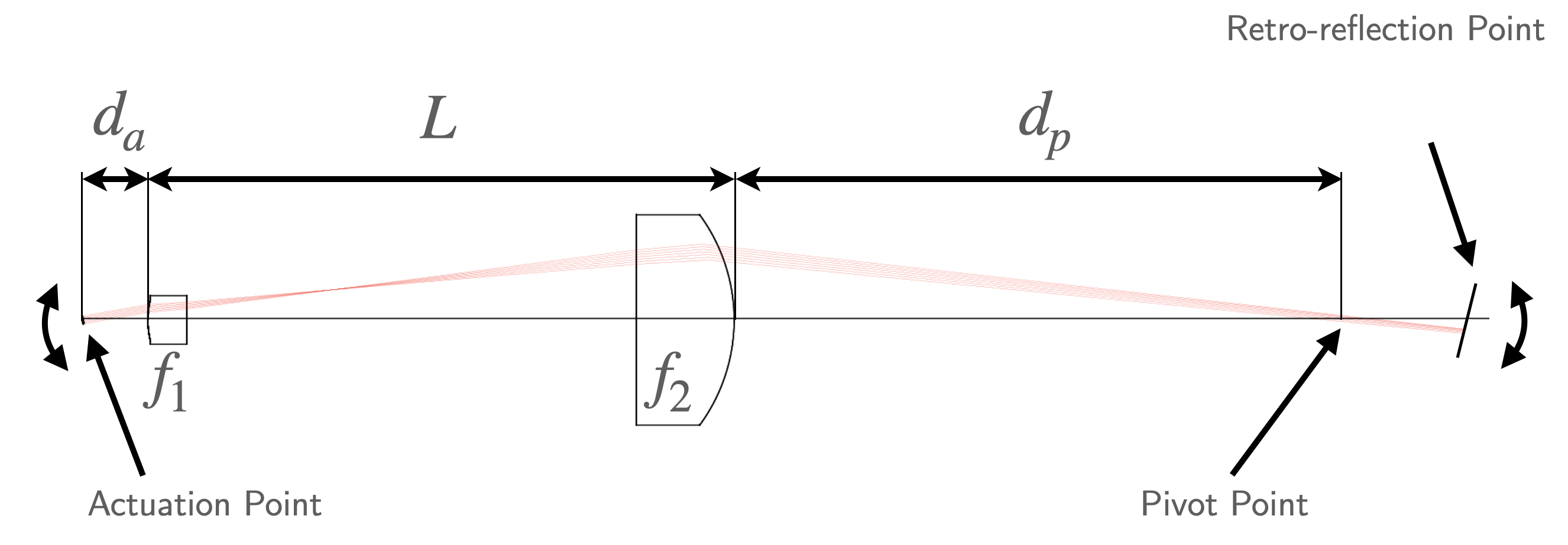
The optical configuration associated with this pivot point scheme consists of having piezo-actuated mirrors on each end of the baseline and tuning the path length of the interferometer beam before a telescope to set the position of the pivot point. In MAGIS-100, a telescope will magnify the beam waist to approximately before the beam interacts with the atoms. We define to be the distance between the first telescope lens and the point about which the pointing of the interferometer beam is actuated (the ‘actuation point’). The position of the pivot point can be adjusted by adjusting , as discussed in section II.3. As indicated in Figure 1, the ‘pivot point’ is defined as the position after the telescope for which angular adjustments about the ‘actuation point’ manifest as purely angular adjustments in the beam, with no associated translations. A mirror further along the beam’s propagation path rotates with the rotating beam so that the retro-reflected beam is colinear with the incident beam.
In Section II.2, we outline the implemenation of the pivot point scheme for the case of performing interferometery over a baseline with a single atom source, as in the case of one of the dark matter search operating modes of MAGIS-100. In this operating mode, co-located, simultaneous atom interferometers using different isotopes of strontium will span the length of the baselineAbe et al. (2021). In Section II.6, we extend the scheme to the case of performing atom gradiometry over baselines, as in the gravitational wave detection operation mode of MAGIS-100. In Section II.7, we explore the prospects for, and challenges of, scaling this scheme to km-scale baselines.
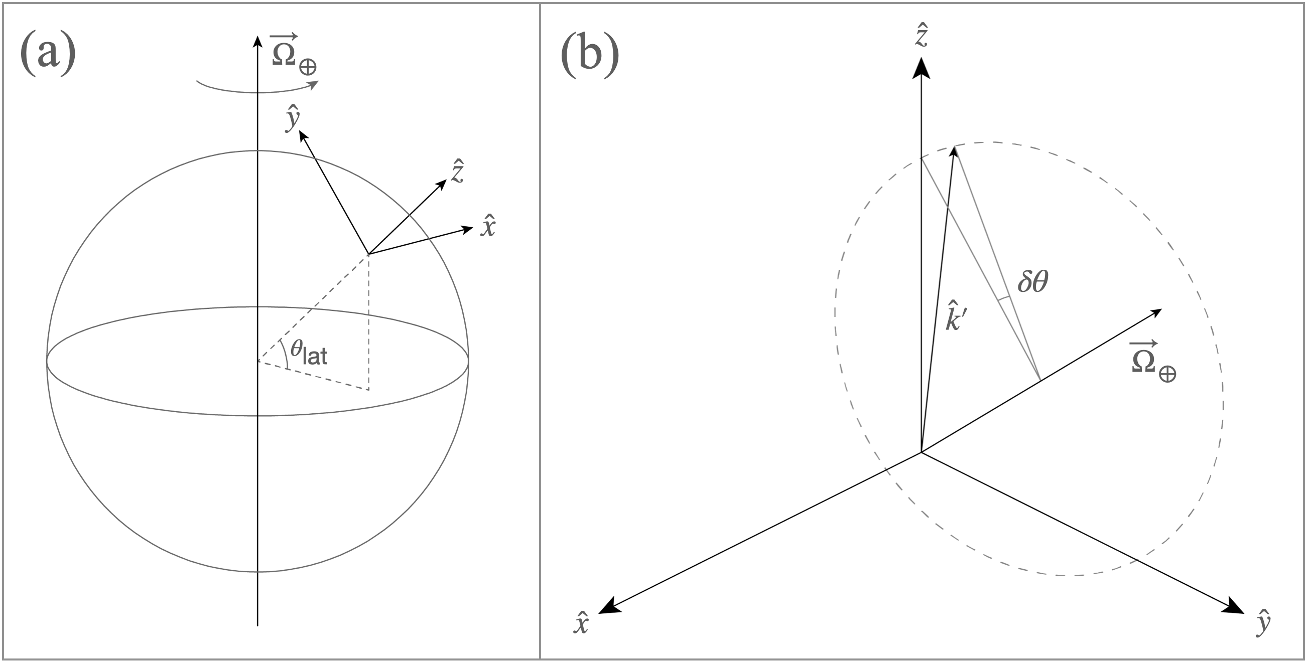
We argue that to first order in small angular deviations, it suffices to consider rotations about a single axis orthogonal to the vertical direction. Figure 2 shows the relationship between the unit vectors which define the lab frame Cartesian coordinate system and the rotation vector of the Earth . Since the axis about which the Earth rotates is not orthogonal to the interferometer axis, , perfectly rotating the interferometer beam against the rotation of the Earth would in general require rotations about the axis corresponding to the rotation vector of the Earth. For small enough interrogation times , the required rotations of the interferometer beam are primarily around the axis. Here we choose the coordinate system so that the interferometer axis is along , the axis points toward the north pole, and the axis points eastward. The components of Earth’s rotation vector in these coordinates have magnitudes and . Consider a rotation matrix which performs rotations by a small angle around the vector . To study the scale of the required rotations of the interferometer beam, we take the beam to be initially pointing along the axis, , and consider the effect of a small Coriolis force compensating rotation on , . To first order in , the required rotation of the interferometer beam is solely about the axis, in the plane: , where is a matrix which rotates a vector an angle about the axis.
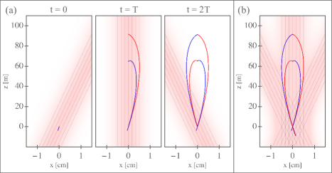
For a single Mach-Zehnder interferometer with interrogation time , which is indicated in Figure 3 and which represents an upper bound on the value of which would be required in MAGIS-100, with . At this maximum angular range, the angle that is made by the axis and the projection of onto the plane is , while the angle that is made by the axis and the projection of onto the plane is . For simplicity of illustration in figures, we will ignore the small projection of onto the z-y plane, though the rotation compensation system will have the capability to implement the corresponding small corrections to the angle of as needed.
In considering the overlap between the interferometry laser beam and the atoms, it is also important to consider deflections of the atom trajectories due to Coriolis forces. The predominant deflections in the trajectories are in the plane because the Coriolis force couples the motion of an atom along the axis with the large ‘upward’ component of its launch velocity, , and does not couple the component of the motion to since the axis of rotation is in the plane. We estimate residual deflections along the axis for the scheme indicated in Figure 3 to be . To simplify the illustration of the pivot point method, we do not consider here dynamics of the atom trajectory in the direction and focus on the plane. We note also that the centrifugal force produces a constant acceleration in the plane which can be thought of as contributing a small correction to a pure gravitational acceleration: , where is the radius of the Earth (taking the Earth to be a perfect sphere)Morin (2008). In practice, the interferometer beam will be aligned to the direction in which the atoms freely fall, which is along . Taking this effect into account, the deflection cited above can be understood as referring to a deflection along a axis, where the primed coordinates refer to a coordinate system which has been slightly rotated around the axis so that the axis points along .
II.2 Coriolis Force Compensation for Long Baseline Interferometry with a Single Atom Source
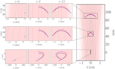
In Figure 3, a Mach-Zehnder pulse sequence with a spacing between beam splitter and mirror pulses and LMT number is performed, wherein an atom cloud is launched at an angle of from the axis with a total velocity of 35.86 m/s. The launch angle is chosen so that the two arms of the interferometer have transverse position at the time of the mirror pulse, and so that the position of the atom cloud is the same for both the first and final beam splitter times. The radius of the earth is taken to be = 6378 km. At time t = 0, an LMT beamsplitter pulse is performed by an interferometer beam angled by about the origin of the lab frame coordinate system which imparts a momentum kick on the upper interferometer arm of (for simplicitly, we assume that the momentum kicks happen instantaneously), where is the wave number of the 679 nm light that is resonant with the resonance of strontium (for the dual-isotope operating mode of MAGIS-100, atom optics will be performed via two-photon Bragg transitions on the 679 nm resonance of strontium Abe et al. (2021)). The atoms then propagate in a superposition of different momentum states subject to Coriolis and centrifugal forces before the mirror pulse at time imparts a momentum kick downward on the upper interferometer arm and a kick with equal magnitude and opposite direction on the lower arm. The atoms then freely propagate for a time before spatially recombining, at which point a final beamsplitter pulse is performed by the beam angled symmetrically about the axis with respect to its angle at time . The choice of pivot point and initial atom cloud kinematics allows for the beam to stay centered on the atom cloud for each interaction time while the interferometer beam is rotated to suppress Coriolis dependent phase shifts and contrast loss. In this example, the pivot point is located at the initial position of the atoms at .
II.3 Tuning the Location of the Pivot Point
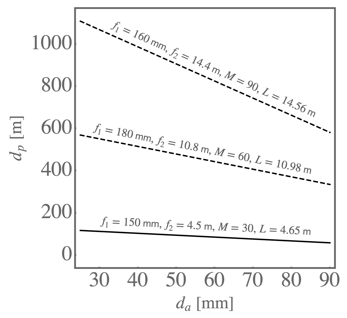
The location of the pivot point can be tuned by adjusting the distance between the actuation point and the first telescope lens, (see Fig. 1). Here we perform ABCD matrix ray tracing calculations in the paraxial and thin lens limits in order to provide an approximate analytic scaling of the pivot point location as a function of . We consider physical optics effects, including also the effects of the exact lens geometries, with numerical calculations using the Zemax software package in section II.5. Here we consider an optical system consisting of two telescope lenses with focal lengths and separated by a distance . A ray pivots a distance away from the first telescope lens, and we define to be the distance from the second telescope lens to the pivot point. The relationship between and can be expressed as
| (1) |
where is the magnification of the telescope and the other parameters are indicated in Fig. 1. For MAGIS-100, two ultrahigh quality spherical lenses (Optimax) Abe et al. (2021) with focal lengths and will be used to magnify a beam focused to a radial waist at the position of the tip tilt mirror to a waist of . A vacuum-compatible, piezo-actuated tip-tilt mirror mount has been procured from Mad City Labs (a custom vacuum-compatible version of the Nano-MTA2) which will enable tilting the interferometer beam before this telescope. This mount has a total angular range of , and for tilts about –which will be made to be approximately orthogonal to the nominal plane of incidence–the total range with which the beam can be angled is because the change in the angle of an incident beam upon reflection from the actuatable tip-tilt mirror is twice the angle of incidence. The telescope will magnify the size of the interferometer beam by a factor of and de-magnify the angles produced by this tilted mirror by that same factor, so that the largest angular tilt allowed by this system in one direction is . This angular range is large enough to perform the sequence shown in Figure 3, whose maximum angular range is in one direction. The tip-tilt retro-reflection mirrorAbe et al. (2021) positioned below this second telescope lens will be angled to keep the reflected beam aligned with the downgoing beam.
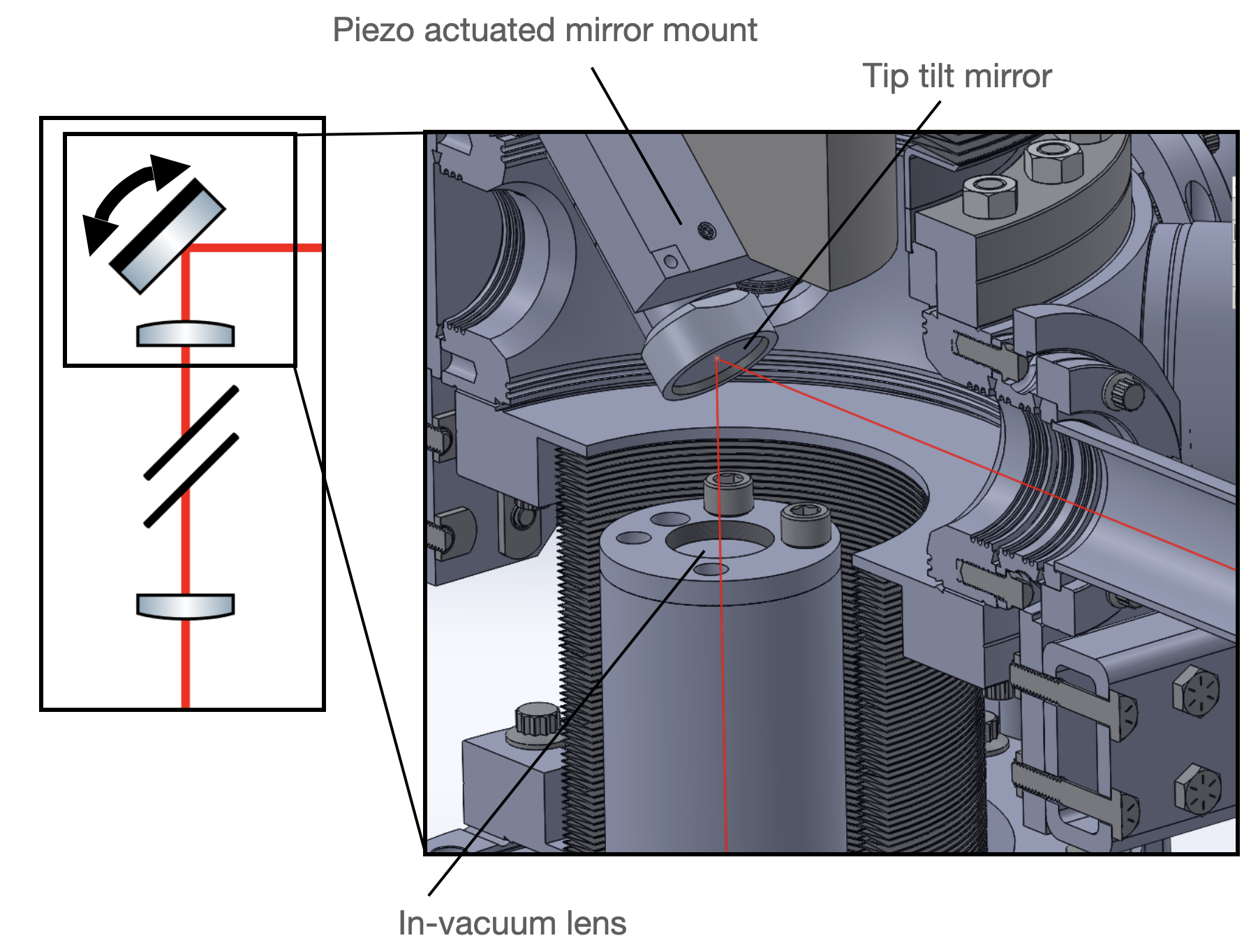
II.4 Tip-Tilt System Mechanical Design
As shown in Figure 4, our design of this section of the tip-tilt system involves the piezo-actuated stage mounted at a angle on a steel post. Out of vacuum stepper motors will adjust the distance between the tip tilt mirror and the first telescope lens to set the pivot point, and the piezos in the Mad City Labs mount will rotate the mirror during an experiment cycle for Coriolis force compensation. We will have the capability to translate the beam with out-of-vacuum stepper motors, which could be useful for fine tuning the alignment of this beam.
II.5 Effect of Spherical Lens Aberrations
In this section, we determine the scale of the aberrations associated with the interplay of the pivot point system and the spherical nature of the telescope lenses through physical optics simulations using the Zemax software package, which capture non-paraxial effects along with effects from the finite extent of the curved face of the telescope lenses. We study the aberrations induced by the spherical telescope lenses on the intensity and phase profiles of the interferometer beam under and beam tilts at five different propagation distances between and after the second telescope lens. We find that the scale of the aberrations induced on the interferometer beam by the spherical nature of the telescope lenses are comparable to the expected phase deviations from surface imperfections in the optics themselves.
Spherical lenses are cheaper to manufacture but induce some anharmonicity into the phase profile of a transmitted Gaussian beam. The dominant mechanism by which aberrations in the interferometer beam are expected to limit the sensitivity of the MAGIS-100 interferometer is the coupling of aberrations to laser pointing jitter and to shot-to-shot fluctuations in initial atom cloud kinematics Abe et al. (2021).
To investigate aberrations associated with the interplay of the tip/tilt system and the telescope, we start with a Gaussian beam profile at a focus with a radial waist incident on the tip/tilt mirror. The first lens has a plano-convex shape and is oriented with its curved face pointing away from the center of the telescope a distance from the tip-tilt mirror. The radius of curvature of this lens is , and its center thickness is . The second telescope lens is also plano-convex and also has its curved face pointing away from the center of the telescope. This lens has radius of curvature and a center thickness of . The distance between the curved faces of the lenses is equal to the sum of their focal lengths , where . Both lenses are made of a material whose index of refraction is approximately (fused silica). The parameter in Figures 5 and 6 denotes the distance from the curved face of the second telescope lens to the plane in which the intensity and phase profiles are evaluated. Here we plot only the cross section of the phase and intensity profiles along the axis for different distances along the axis, which for rotations about the axis is where the dominant sources of aberration are under rotations of the beam.
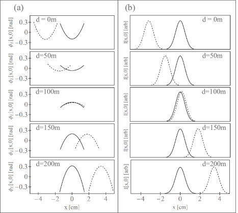
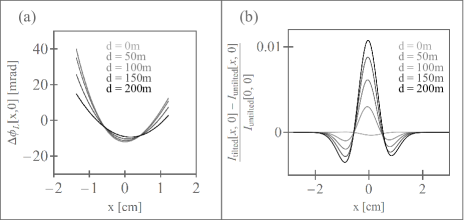
For ease of visualization, the phase profile plots ignore a phase factor varying linearly in that corresponds to the angle of the beam as calculated purely by ray tracing. We see no remarkable aberrations in the intensity profile of the beam, and the aberrations to the phase profile, as seen in Figure 6, are on length scales on the order of the beam size. Over a range centered on the center of the beam, the phase aberrations have a maximum magnitude of , which is comparable to the expected phase deviations from surface imperfections in the optics themselves. The size of the atom cloud is or less, so beyond this range, most atoms will not sample the inhomogeneity in the laser phase profile.
II.6 Coriolis Compensation for Atom Gradiometry
An atom gradiometer is an apparatus in which multiple atom interferometers are spaced over a long baseline. MAGIS-100 is designed to be able to operate in this mode for mid-band gravitational wave detection and certain dark matter searches Abe et al. (2021). The influence of Coriolis forces can be suppressed in a gradiometer configuration by performing multiloop sequences Dubetsky and Kasevich (2006); Abe et al. (2021), but this approach also suppresses the response of the interferometer to low frequency signals. The pivot point method outlined in Section II.1 could be used in a gradiometer mode where the signals of interest are of a lower frequency. Performing long baseline rotation compensation with the pivot point method for atom gradiometry relies on the ability to adjust the initial positions and velocities of the different atom clouds individually. In Figure 7, three atom interferometers are separated by 45 m and span roughly the length of the 100 m baseline. The sequence presented in Figure 7 is a Mach-Zehnder interferometer with a interrogation time and momentum transfer at each atom-laser interaction time. The atom clouds from bottom to top are launched with respective angles of approximately , , and relative to the axis, each with a total initial velocity of . The interferometer beam is initially angled by , and the atom clouds are prepared with a lateral offset from the interferometer baseline of , read from bottom to top.
II.7 Prospects For, and Challenges of, Scaling Up to Longer Baselines
The pivot point method can be extended to future larger baseline interferometers, but alternate telescope parameters are required in order to place the pivot point near the end of the longer baseline and ensure the ability to tune it over a range about that point. Only two-lens telescopes are considered here, though telescopes with three or more lenses may also be feasible. Figure 8 presents a few possible lens combinations, referencing Equation (1). If the range over which is adjusted is held fixed as the baseline increases, a larger telescope magnification is required in order to scan the pivot point over a larger range. In general, as one increases the baseline of the interferometer, a longer two-lens telescope is required. One challenge associated with performing Coriolis force compensation with the pivot point method over longer baselines is that the required deflections of the interferometer beam are larger, which requires vacuum pipes with larger internal diameters. The diameter of the second telescope lens also increases with increasing baseline length. For a Mach-Zehnder interferometer sequence wherein the classical trajectories of the atoms span km-scale baselines, the required rotations about the pivot point are roughly for , and . In order for the interferometer beam to not clip on the edge of optics or on the internal diameter of vacuum pipes, the bottom telescope lens and the internal diameter of the vacuum pipes near the second telescope lens would need to have diameters on the meter scale, which would have significant associated costs.
III Interferometer Laser Beam Delivery System
III.1 Beam Delivery System Mechanical Design
The laser transport system transports the interferometer beam from where it is generated in the laser room over to the shaft where the interferometry is being done. It uses a combination of stable mechanical mounts, a relay imaging system, and a short fiber to provide both passive pointing stability and a stable multi-Watt interferometer beam power.
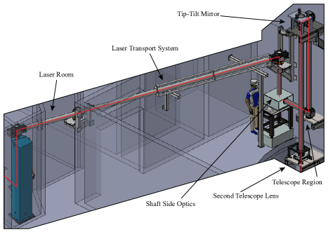
Building a dedicated laser room serves two critical functions: temperature control and laser safety. Having a dedicated temperature-controlled room suppresses associated drifts and reduces the frequency of various laser feedback loops falling out of lock. Also, consolidating the laser system in a central, interlocked room is required for laser safety purposes. Constructing a laser room within a facility not purpose-built for atom interferometry presents a challenge: It can be difficult to position the laser room in close proximity to the main experiment without resorting to costly and time-consuming structural modifications to the existing facility in order to accommodate the laser room’s spatial footprint. Consequently, this constraint may necessitate situating the laser room at a considerable distance from the main experiment. MAGIS-100 is being constructed in the MINOS Service Building at Fermilab, which was originally built as an access building for underground experiments. Facilities constraints require the interferometry laser beam to be transported to the shaft over horizontally, and also for the beam to be transported at a height of above the floor of the building.
A limitation of fiber-based laser transport is that for multi-Watt laser powers and long fibers, losses from stimulated Brillouin scattering become a significant concernKobyakov, Sauer, and Chowdhury (2010). It is productive to maximize the power of the beam that is delivered to the atoms because larger beam powers result in larger Rabi frequencies, which are advantageous for the reasons outlined in Section II.1. We therefore opt to transport the beam in free space. Free space transport, however, poses its own challenges since it is more susceptible to alignment drifts in the delivery optics.
To address these challenges, we include a long, single-mode fiber (short enough that we do not observe stimulated Brillouin scattering) after the free space laser transport to remove the influence of pointing fluctuations from all preceding optics and free-standing support structures. We will then anchor all subsequent optics to a structurally stable floor and wall by the shaft. With this short fiber, pointing fluctuations in the beam manifest as fluctuating fiber coupling efficiencies. After the short fiber, we will pick off a small amount of light to measure the post-fiber power of the beam and feed that signal back to the laser room, where an acousto-optic modulator will adjust and stabilize this power. The lock point must be set slightly below the maximum achievable laser power in order to correct for dips in the post-fiber power of the beam caused by drifts in the laser transport. Improved stability of the laser transport system suppresses the magnitude of these power drops, allowing for a higher lock point, and an increase in the power delivered to the atoms. This combination of a short fiber and a power stabilizing feedback system enables the beam to have both stable pointing and power.
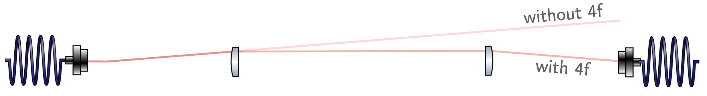
The delivery optics will drift on hour timescales in response to temperature changes in the area, and fluctuate on faster timescales in response to seismic and anthropogenic vibrations in the environment, along with air currents. To suppress the influence of pointing fluctuations on the fiber coupling efficiency, we opted to add two long focal length lenses in a ‘4f’ relay-imaging configuration to better passively isolate the coupling efficiency of the interferometer beam against pointing fluctuations of the steering optics, effectively reducing the lever arm associated with the beam propagation (see Fig. 9). Moreover, the interferometer beam propagates in rough vacuum () to suppress the influence of air currents on the pointing of the beam. We tested the efficacy of using a relay imaging system to stabilize the fiber coupling efficiency in a full-scale prototype of the laser transport system (see Sec. III.2 for further details).
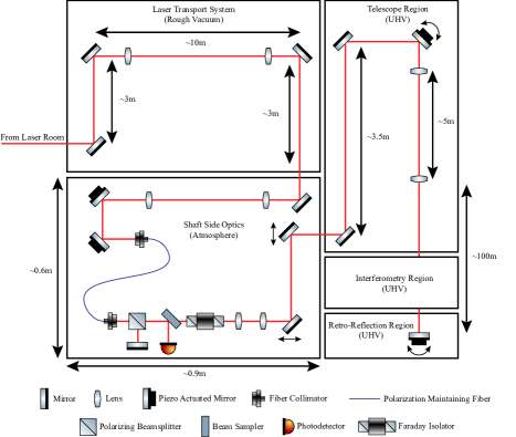
The ‘shaft-side optics’ (see Figures 10 and 11) consist of the short fiber described above, which provides initial spatial filtering of the beam Abe et al. (2021), a photodetector for power monitoring (used for power stabilization feedback as described above), optics for a fiber-phase-noise-cancellation setup, and a short telescope. One fixed mirror on the shaft-side breadboard will direct the interferometer beam to a short telescope, which shapes the beam to match the mode of the short fiber. Two subsequent piezo-actuated mirror mounts adjust the angle and lateral position of the interferometer beam into the fiber. These mounts can be adjusted every to compensate for long timescale drifts in the laser transport system alignment. The polarizing beamsplitter and mirror just after the fiber back-reflect a small portion of the interferometer beam as part of a fiber-phase-noise-cancellation scheme DeRose et al. (2023); Ma et al. (1994); Abe et al. (2021). A subsequent Faraday isolator keeps preceding optics protected from back-reflected light, and then a short telescope shapes the interferometer beam so that it is focused to a radial waist of at the location of the tip-tilt mirror, away. Two subsequent mirrors mounted to motorized translation stages provide fine adjustment of the lateral alignment of the interferometer beam into the telescope region. Adjusting the lateral position of the interferometer beam may also be useful to keep the beam centered on atoms for extended LMT sequences when the effective mirror and beamsplitter pulses take a non-negligible amount of time.
The ‘telescope region’ (see Figure 10) exists in UHV () and consists of of initial free propagation (1 m of horizontal propagation and 3.5 m of vertical), which further cleans the spatial mode of the beamAbe et al. (2021). The beam then reflects off the tip-tilt mirror, whose mechanical configuration is discussed earlier in Section II.4, and travels through the telescope discussed in section II.5 which expands the interferometer beam to a waist of . The piezo-actuated mirror stage at the bottom of the shaft Abe et al. (2021) retro-reflects the interferometer beam back up the shaft. The telescope de-magnifies angles by a factor equal to its magnification , reducing the impact of angular fluctuations of pre-telescope optics.
III.2 Full Scale Prototype of Laser Transport System
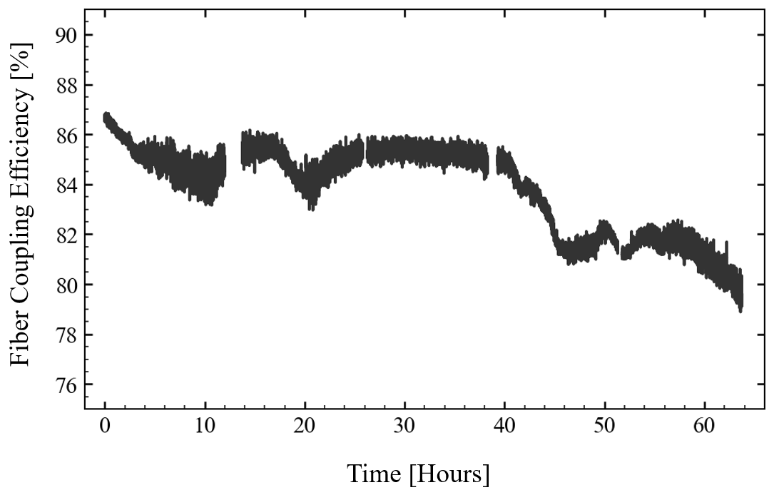
We constructed a prototype of the laser transport system to demonstrate the feasibility of coupling the interferometer beam into a short fiber following of free propagation and to monitor the passive stability of the fiber coupling efficiency over time scales of many hours in the presence of environmental perturbations. This test was performed in a horizontal configuration (see Fig. 12) on the rooftop of the Fermilab Accelerator Science and Technology accelerator in the New Muon Lab on the Fermilab campus and included the right-angle turns that will be necessary to elevate the beam off the floor in the final configuration. The relay imaging system was composed of two f = 5 m lenses in a ‘4f’ configuration respectively mounted to two vacuum chambers which each housed a fixed right angle mirror. This proof of concept was without any of the vertical support structures planned for the full laser transport system, since those structures were still being designed. As shown in Figure 13, over a continuous 40-hour period, we successfully maintained a fiber coupling efficiency without the need for any alignment adjustments.
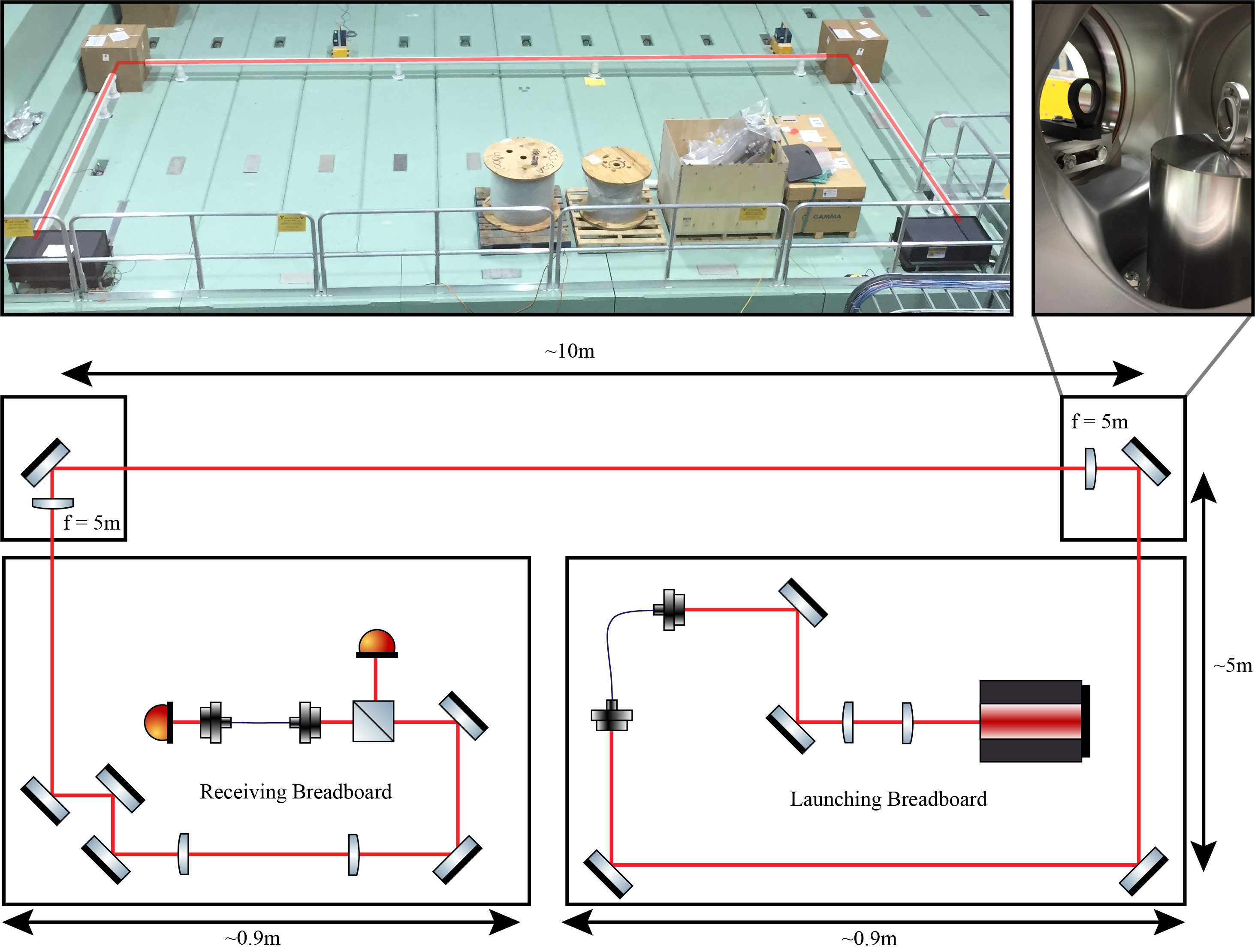
The prototype consisted of a ‘launching’ breadboard which consisted of a laser (CivilLaser) which was coupled into a fiber to clean the spatial mode of the beam, and directed to a right angle mirror and 5 m focal length lens (EKSMA 110-0289E) away. The beam then propagated m, before reflecting off a second right angle mirror paired with a second 5 m focal length lens. Subsequently, the beam propagated over a distance to the ‘receiving’ breadboard. On this board, three mirrors set the alignment of the beam into a short telescope which mode-matched the beam into a short fiber. A 50:50 beamsplitter and photodiode combination just before the fiber monitored the power of the beam before the fiber, and a photodiode after the fiber measured the post-fiber power. To extract a coupling efficiency, we took the ratio of the real-time power before and after the fiber so that the measured coupling efficiency was independent of power fluctuations in the laser.
We obtained best stability results when using Thorlabs Polaris mirror mounts (POLARIS-K1S4) with the pitch and yaw lead screw axes locked with locking nuts. To suppress the higher frequency jitter induced by air currents, the beam was enclosed by PVC pipe in the long regions of free-space propagation, and cardboard boxes with two holes cut in them served as local enclosures for the right angle mirrors. Both the launching and receiving breadboards were enclosed with hardboard enclosure material from Thorlabs. While air current shielding did not noticeably affect the long term stability, it slightly suppressed root mean square (rms) fluctuations from to integrated over a 20 mHz to 4 kHz band. As shown in Figure 13, we measured a fiber coupling efficiency over a period despite this path length. To compensate for drifts on these large timescales, automated tweaks of fiber coupling with piezo-controlled mirror mounts, indicated in Figure 10, will be used.
In the near future, we plan to test the stability in the final vertical configuration to evaluate the impacts of the vertical support structures.
IV Conclusion
In this paper, we introduced a method for Coriolis force compensation in long-baseline atom interferometers, provided specific implementation details for MAGIS-100, and presented the design of the beam delivery system for MAGIS-100. In the future, we will demonstrate the pivot point method experimentally in MAGIS-100 and further evaluate the feasibility of using this method for future km-baseline interferometers.
Acknowledgements.
We thank Jason Hogan and James Santucci for valuable discussions and technical contributions. This project is funded in part by the Gordon and Betty Moore Foundation Grant GBMF7945. Some of the work presented in this document leveraged the resources of the Fermi National Accelerator Laboratory (Fermilab), a U.S. Department of Energy, Office of Science, HEP User Facility. Fermilab is managed by Fermi Research Alliance, LLC (FRA), acting under Contract No. DE-AC02-07CH11359. This work is supported in part by the U.S. Department of Energy, Office of Science, QuantiSED Intitiative. We also acknowledge support from the David and Lucile Packard Foundation (Fellowship for Science and Engineering).Author Declarations
Conflict of Interest
The authors have no conflicts to disclose.
Author Contributions
Jonah Glick: Conceptualization (equal), Methodology (equal), Investigation (lead), Validation (equal), Formal Analysis (lead), Writing – original draft (lead). Writing – review & editing (equal). Zilin Chen: Methodology (equal), Investigation (supporting), Validation (equal), Writing – review & editing (supporting). Tejas Deshpande: Conceptualization (equal), Methodology (equal), Investigation (supporting), Validation (equal), Supervision (equal), Writing – review & editing (supporting). Yiping Wang: Conceptualization (equal), Methodology (equal), Investigation (supporting), Validation (equal), Writing – review & editing (supporting). Tim Kovachy: Conceptualization (equal), Methodology (equal), Validation (equal), Supervision (equal), Writing – review & editing (equal).
Data Availability Statement
The data that support the findings of this study are available from the corresponding author upon reasonable request.
Conflict of Interest Statement
The authors have no conflicts to disclose.
References
- Fray et al. (2004) S. Fray, C. A. Diez, T. W. Hänsch, and M. Weitz, “Atomic interferometer with amplitude gratings of light and its applications to atom based tests of the equivalence principle,” Phys. Rev. Lett. 93, 240404 (2004).
- Bonnin et al. (2013) A. Bonnin, N. Zahzam, Y. Bidel, and A. Bresson, “Simultaneous dual-species matter-wave accelerometer,” Phys. Rev. A 88, 043615 (2013).
- Bouchendira et al. (2011) R. Bouchendira, P. Cladé, S. Guellati-Khélifa, F. m. c. Nez, and F. m. c. Biraben, “New determination of the fine structure constant and test of the quantum electrodynamics,” Phys. Rev. Lett. 106, 080801 (2011).
- Tarallo et al. (2014) M. G. Tarallo, T. Mazzoni, N. Poli, D. V. Sutyrin, X. Zhang, and G. M. Tino, “Test of einstein equivalence principle for 0-spin and half-integer-spin atoms: Search for spin-gravity coupling effects,” Phys. Rev. Lett. 113, 023005 (2014).
- Schlippert et al. (2014) D. Schlippert, J. Hartwig, H. Albers, L. L. Richardson, C. Schubert, A. Roura, W. P. Schleich, W. Ertmer, and E. M. Rasel, “Quantum Test of the Universality of Free Fall,” Phys. Rev. Lett. 112, 203002 (2014).
- Kuhn et al. (2014) C. C. N. Kuhn, G. D. McDonald, K. S. Hardman, S. Bennetts, P. J. Everitt, P. A. Altin, J. E. Debs, J. D. Close, and N. P. Robins, “A Bose-condensed, simultaneous dual-species Mach–Zehnder atom interferometer,” New J. Phys. 16, 073035 (2014).
- Rosi et al. (2014) G. Rosi, F. Sorrentino, L. Cacciapuoti, M. Prevedelli, and G. Tino, “Precision measurement of the newtonian gravitational constant using cold atoms,” Nature 510, 518–521 (2014).
- Barrett et al. (2015) B. Barrett, L. Antoni-Micollier, L. Chichet, B. Battelier, P.-A. Gominet, A. Bertoldi, P. Bouyer, and A. Landragin, “Correlative methods for dual-species quantum tests of the weak equivalence principle,” New J. Phys. 17, 085010 (2015).
- Biedermann et al. (2015) G. W. Biedermann, X. Wu, L. Deslauriers, S. Roy, C. Mahadeswaraswamy, and M. A. Kasevich, “Testing gravity with cold-atom interferometers,” Phys. Rev. A 91, 033629 (2015).
- Zhou et al. (2015) L. Zhou, S. Long, B. Tang, X. Chen, F. Gao, W. Peng, W. Duan, J. Zhong, Z. Xiong, J. Wang, Y. Zhang, and M. Zhan, “Test of equivalence principle at level by a dual-species double-diffraction raman atom interferometer,” Phys. Rev. Lett. 115, 013004 (2015).
- Barrett et al. (2016) B. Barrett, L. Antoni-Micollier, L. Chichet, B. Battelier, T. Lévèque, A. Landragin, and P. Bouyer, “Dual matter-wave inertial sensors in weightlessness,” Nat. Comm. 7, 13786 (2016).
- Williams et al. (2016) J. Williams, S. wey Chiow, N. Yu, and H. Müller, “Quantum test of the equivalence principle and space-time aboard the International Space Station,” New J. Phys. 18, 025018 (2016).
- Rosi et al. (2017) G. Rosi, G. D’Amico, L. Cacciapuoti, F. Sorrentino, M. Prevedelli, M. Zych, Č. Brukner, and G. Tino, “Quantum test of the equivalence principle for atoms in coherent superposition of internal energy states,” Nat. Comm. 8, 1–6 (2017).
- Asenbaum et al. (2017) P. Asenbaum, C. Overstreet, T. Kovachy, D. D. Brown, J. M. Hogan, and M. A. Kasevich, “Phase shift in an atom interferometer due to spacetime curvature across its wave function,” Phys. Rev. Lett. 118, 183602 (2017).
- Overstreet et al. (2018) C. Overstreet, P. Asenbaum, T. Kovachy, R. Notermans, J. M. Hogan, and M. A. Kasevich, “Effective inertial frame in an atom interferometric test of the equivalence principle,” Phys. Rev. Lett. 120, 183604 (2018).
- Parker et al. (2018) R. H. Parker, C. Yu, W. Zhong, B. Estey, and H. Müller, “Measurement of the fine-structure constant as a test of the standard model,” Science 360, 191–195 (2018).
- Asenbaum et al. (2020a) P. Asenbaum, C. Overstreet, M. Kim, J. Curti, and M. A. Kasevich, “Atom-interferometric test of the equivalence principle at the level,” Phys. Rev. Lett. 125, 191101 (2020a).
- Morel et al. (2020) L. Morel, Z. Yao, P. Cladé, and S. Guellati-Khélifa, “Determination of the fine-structure constant with an accuracy of 81 parts per trillion,” Nature 588, 61–65 (2020).
- Overstreet et al. (2022) C. Overstreet, P. Asenbaum, J. Curti, M. Kim, and M. A. Kasevich, “Observation of a gravitational aharonov-bohm effect,” Science 375, 226–229 (2022).
- Hamilton et al. (2015) P. Hamilton, M. Jaffe, P. Haslinger, Q. Simmons, H. Müller, and J. Khoury, “Atom-interferometry constraints on dark energy,” Science 349, 849–851 (2015).
- Dimopoulos et al. (2008) S. Dimopoulos, P. W. Graham, J. M. Hogan, M. A. Kasevich, and S. Rajendran, “Atomic gravitational wave interferometric sensor,” Phys. Rev. D 78, 122002 (2008).
- Graham et al. (2013) P. W. Graham, J. M. Hogan, M. A. Kasevich, and S. Rajendran, “New method for gravitational wave detection with atomic sensors,” Phys. Rev. Lett. 110, 171102 (2013).
- Graham et al. (2016a) P. W. Graham, J. M. Hogan, M. A. Kasevich, and S. Rajendran, “Resonant mode for gravitational wave detectors based on atom interferometry,” Phys. Rev. D 94, 104022 (2016a).
- Chaibi et al. (2016) W. Chaibi, R. Geiger, B. Canuel, A. Bertoldi, A. Landragin, and P. Bouyer, “Low frequency gravitational wave detection with ground-based atom interferometer arrays,” Phys. Rev. D 93, 021101 (2016).
- Hogan et al. (2011) J. M. Hogan, D. Johnson, S. Dickerson, T. Kovachy, A. Sugarbaker, S.-w. Chiow, P. W. Graham, M. A. Kasevich, B. Saif, S. Rajendran, et al., “An atomic gravitational wave interferometric sensor in low earth orbit (agis-leo),” Gen. Relativ. Gravit. 43, 1953–2009 (2011).
- El-Neaj et al. (2020) Y. A. El-Neaj, C. Alpigiani, S. Amairi-Pyka, H. Araújo, A. Balaž, A. Bassi, L. Bathe-Peters, B. Battelier, A. Belić, E. Bentine, J. Bernabeu, A. Bertoldi, R. Bingham, et al., “AEDGE: Atomic Experiment for Dark Matter and Gravity Exploration in Space,” EPJ Quantum Technol. 7, 6 (2020).
- Abe et al. (2021) M. Abe et al. (MAGIS-100), “Matter-wave Atomic Gradiometer Interferometric Sensor (MAGIS-100),” Quantum Sci. Technol. 6, 044003 (2021), arXiv:2104.02835 [physics.atom-ph] .
- Arvanitaki et al. (2018) A. Arvanitaki, P. W. Graham, J. M. Hogan, S. Rajendran, and K. Van Tilburg, “Search for light scalar dark matter with atomic gravitational wave detectors,” Phys. Rev. D 97, 075020 (2018).
- Graham et al. (2016b) P. W. Graham, D. E. Kaplan, J. Mardon, S. Rajendran, and W. A. Terrano, “Dark matter direct detection with accelerometers,” Phys. Rev. D 93, 075029 (2016b).
- Banerjee et al. (2022) A. Banerjee, G. Perez, M. Safronova, I. Savoray, and A. Shalit, “The phenomenology of quadratically coupled ultra light dark matter,” arXiv preprint arXiv:2211.05174 (2022).
- Kovachy et al. (2015) T. Kovachy, P. Asenbaum, C. Overstreet, C. Donnelly, S. Dickerson, A. Sugarbaker, J. Hogan, and M. Kasevich, “Quantum superposition at the half-metre scale,” Nature 528, 530–533 (2015).
- Badurina et al. (2020) L. Badurina, E. Bentine, D. Blas, K. Bongs, D. Bortoletto, T. Bowcock, K. Bridges, W. Bowden, O. Buchmueller, C. Burrage, J. Coleman, G. Elertas, J. Ellis, C. Foot, V. Gibson, M. Haehnelt, T. Harte, S. Hedges, R. Hobson, M. Holynski, T. Jones, M. Langlois, S. Lellouch, M. Lewicki, R. Maiolino, P. Majewski, S. Malik, J. March-Russell, C. McCabe, D. Newbold, B. Sauer, U. Schneider, I. Shipsey, Y. Singh, M. Uchida, T. Valenzuela, M. van der Grinten, V. Vaskonen, J. Vossebeld, D. Weatherill, and I. Wilmut, “AION: an atom interferometer observatory and network,” Journal of Cosmology and Astroparticle Physics 2020, 011–011 (2020).
- Canuel et al. (2018) B. Canuel, A. Bertoldi, L. Amand, E. P. di Borgo, T. Chantrait, C. Danquigny, M. D. Álvarez, B. Fang, A. Freise, R. Geiger, J. Gillot, S. Henry, J. Hinderer, D. Holleville, J. Junca, G. Lefèvre, M. Merzougui, N. Mielec, T. Monfret, S. Pelisson, M. Prevedelli, S. Reynaud, I. Riou, Y. Rogister, S. Rosat, E. Cormier, A. Landragin, W. Chaibi, S. Gaffet, and P. Bouyer, “Exploring gravity with the MIGA large scale atom interferometer,” Scientific Reports 8 (2018), 10.1038/s41598-018-32165-z.
- Zhan et al. (2019) M.-S. Zhan, J. Wang, W.-T. Ni, D.-F. Gao, G. Wang, L.-X. He, R.-B. Li, L. Zhou, X. Chen, J.-Q. Zhong, B. Tang, Z.-W. Yao, L. Zhu, Z.-Y. Xiong, S.-B. Lu, G.-H. Yu, Q.-F. Cheng, M. Liu, Y.-R. Liang, P. Xu, X.-D. He, M. Ke, Z. Tan, and J. Luo, “ZAIGA: Zhaoshan long-baseline atom interferometer gravitation antenna,” International Journal of Modern Physics D 29, 1940005 (2019).
- Hartwig et al. (2015) J. Hartwig, S. Abend, C. Schubert, D. Schlippert, H. Ahlers, K. Posso-Trujillo, N. Gaaloul, W. Ertmer, and E. M. Rasel, “Testing the universality of free fall with rubidium and ytterbium in a very large baseline atom interferometer,” New Journal of Physics 17, 035011 (2015).
- Dickerson et al. (2013) S. M. Dickerson, J. M. Hogan, A. Sugarbaker, D. M. S. Johnson, and M. A. Kasevich, “Multiaxis inertial sensing with long-time point source atom interferometry,” Phys. Rev. Lett. 111, 083001 (2013).
- Lan et al. (2012) S.-Y. Lan, P.-C. Kuan, B. Estey, P. Haslinger, and H. Müller, “Influence of the coriolis force in atom interferometry,” Phys. Rev. Lett. 108, 090402 (2012).
- Kobyakov, Sauer, and Chowdhury (2010) A. Kobyakov, M. Sauer, and D. Chowdhury, “Stimulated brillouin scattering in optical fibers,” Adv. Opt. Photon. 2, 1–59 (2010).
- Asenbaum et al. (2020b) P. Asenbaum, C. Overstreet, M. Kim, J. Curti, and M. A. Kasevich, “Atom-interferometric test of the equivalence principle at the level,” Phys. Rev. Lett. 125, 191101 (2020b).
- Sugarbaker et al. (2013) A. Sugarbaker, S. M. Dickerson, J. M. Hogan, D. M. S. Johnson, and M. A. Kasevich, “Enhanced atom interferometer readout through the application of phase shear,” Phys. Rev. Lett. 111, 113002 (2013).
- Morin (2008) D. Morin, Introduction to Classical Mechanics: With Problems and Solutions (Cambridge University Press, 2008).
- Dubetsky and Kasevich (2006) B. Dubetsky and M. A. Kasevich, “Atom interferometer as a selective sensor of rotation or gravity,” Phys. Rev. A 74, 023615 (2006).
- DeRose et al. (2023) K. DeRose, T. Deshpande, Y. Wang, and T. Kovachy, “High-power, low-phase-noise, frequency-agile laser system for delivering fiber-noise-canceled pulses for strontium clock atom interferometry,” Opt. Lett. 48, 3893–3896 (2023).
- Ma et al. (1994) L.-S. Ma, P. Jungner, J. Ye, and J. L. Hall, “Delivering the same optical frequency at two places: accurate cancellation of phase noise introduced by an optical fiber or other time-varying path,” Opt. Lett. 19, 1777–1779 (1994).