Structured Two-Stage True-Time-Delay Array Codebook Design for Multi-User Data Communication
Abstract
Wideband millimeter-wave and terahertz (THz) systems can facilitate simultaneous data communication with multiple spatially separated users. It is desirable to orthogonalize users across sub-bands by deploying frequency-dependent beams with a sub-band-specific spatial response. True-Time-Delay (TTD) antenna arrays are a promising wideband architecture to implement sub-band-specific dispersion of beams across space using a single radio frequency (RF) chain. This paper proposes a structured design of analog TTD codebooks to generate beams that exhibit quantized sub-band-to-angle mapping. We introduce a structured Staircase TTD codebook and analyze the frequency-spatial behaviour of the resulting beam patterns. We develop the closed-form two-stage design of the proposed codebook to achieve the desired sub-band-specific beams and evaluate their performance in multi-user communication networks.
I Introduction
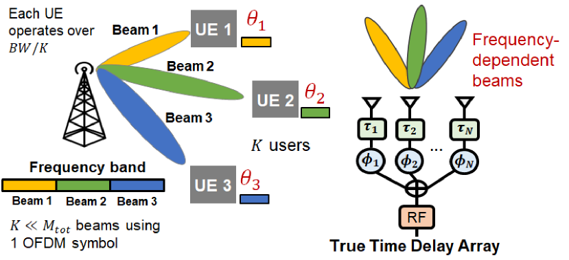
Millimeter-wave and terahertz (THz) systems offer large bandwidths[1, 2, 3] which, besides enabling high data rates, can facilitate simultaneous data communication with multiple spatially separated users occupying non-overlapping sub-bands. To support such sub-band-specific data communication, base stations need to deploy directional beams with a sub-band-specific spatial response, where all frequency resources within a sub-band form a beam to serve a particular user[4, 5], as shown in Fig. 1. While the conventional analog phased arrays can only generate frequency-flat spatial responses, fully digital or hybrid analog-digital arrays that leverage multiple RF chains for enhanced beamforming capabilities incur high costs and power consumption.
True-Time-Delay (TTD) arrays are a promising candidate for sub-band beamforming owing to their low-complexity implementation of frequency-dependent beams using a single RF chain. Works in [6, 7, 8, 9] use analog TTD arrays to implement a fully dispersive rainbow beam codebook scanning a continuous range of angles for expedited beam training. Recent works, namely Joint-Phase-Time-Arrays (JPTA)[4] and mmFlexible[5], leverage analog TTD-inspired architectures to generate beams with quantized sub-band-specific dispersion in space. The algorithm proposed in [4] iteratively optimizes the per-antenna delays and phase shifts, whereas the algorithm in [5] is based on a closed-form Least-Squares solution. ††This work was supported by the NSF under grant 1955672.
In contrast with [4, 5], this paper adopts a structured beam-synthesis methodology rooted in principles of array design and frequency-spatial beam-pattern analysis to design sub-band beams, rather than target-based optimization or pattern-fitting. The main contributions of the paper are summarized as follows: We propose a structured delay-phase codebook called Staircase TTD codebook in Sec. II, and study the frequency-spatial characteristics of resulting beams in Sec. III. We then develop a closed-form design of the proposed codebook to implement dual-stage frequency-spatial filtering to achieve the required sub-band-specific spatial responses in Sec. IV. Sec. V presents simulation results that compare the performance of Staircase TTD codebooks with state-of-the-art methods. Finally, Sec. VII presents concluding remarks and future steps.
Notation: Scalars, vectors, and matrices are denoted by non-bold, bold lower-case, and bold upper-case letters, respectively. For a given matrix , and denote matrices with the element given by and respectively. Further, the element of a vector is denoted as . Conjugate, transpose and Hermitian transpose are denoted by , , and respectively.
II System Model
We consider a cellular system where a Base Station (BS) simultaneously serves users (UE) spatially distributed at angles . The BS operates over the bandwidth and transmits an Orthogonal Frequency Division Multiplexing (OFDM) signal with a total of subcarriers at carrier frequency , where the frequency of the subcarrier is given by . Each UE operates over a non-overlapping contiguous bandwidth with a total of subcarriers.
The BS is equipped with an analog TTD array with uniform half-wavelength spacing (, where is the speed of light). Each antenna element is controlled with time delays and phase shifts, which are denoted by vectors respectively. The frequency-dependent precoder at the BS is thus obtained as follows:
| (1) |
The goal is to design the per-antenna delays and phase shifts to generate beams with the desired sub-band to angle mapping.
II-A Uniform Staircase TTD codebook
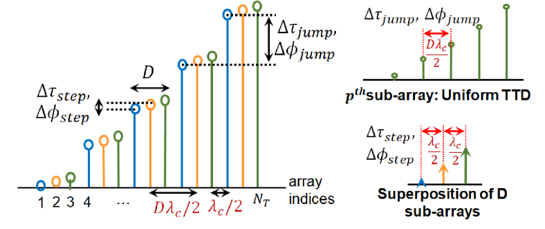
We introduce the uniform Staircase TTD codebook that is designed based on two sets of delay and phase increments applied at different antenna spacing intervals. The high-frequency delay and phase increments (, ) occur at every consecutive antenna element, whereas the low-frequency increments (, ) occur at a spacing of antenna elements. The resulting delay and phase vectors resemble a staircase function of step size , where the delay at the antenna is given as follows:
| (2) |
where denotes the modulo operator. The per-antenna phase shifts apply increments in a similar manner. Under special condition , it is possible to realize the Kronecker decomposition of the Staircase TTD combiner in (1) to obtain delays and phases that can be expressed as follows:
| (3) | ||||
where denotes the Kronecker summation of two vectors and , defined as , where denotes Kronecker product. For ease of notation, we define and as the Staircase jump parameters, and and as the step parameters as shown in Fig. 2, since the two parameters govern the inter- and intra- step behaviour of the staircase TTD codebook. Consequently, the delays and phases of the uniform Staircase TTD codebook in (2) can be expressed as follows:
| (4) |
| (5) |
III Frequency-spatial analysis of Staircase TTD
III-A Frequency-angle mapping of each sub-array
The uniform Staircase TTD codebook can be visualized as the superposition of uniform TTD sub-arrays (shown in Fig. 2) with antenna spacing , delay spacing and phase spacing . Since the antenna spacing exceeds the critical spacing by a factor of , the resulting beams exhibit grating lobes or spectral copies for each frequency.
Each sub-array would have an identical frequency-beam-centre mapping owing to identical uniform TTD array parameters. Based on (1), the precoder for each sub-array is determined by:
| (6) |
The array response vector for each sub-array with antenna-spacing at an angle of arrival can be given as follows:
| (7) |
The frequency-dependent beamforming gain at angle can thus be obtained as , which can be simplified as follows:
| (8) |
where . The beam-centre for frequency , denoted by or , corresponds to the angle that maximizes the beamforming gain function, i.e. , and can be obtained by solving , . Owing to grating lobes, each frequency will have beam-centre solutions, which are given as follows:
| (9) | ||||
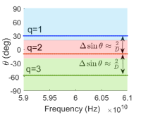
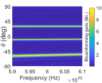
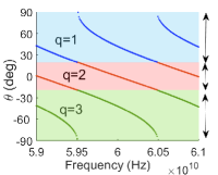
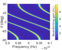
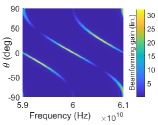
where each value of corresponds to a distinct spectral copy of the main beam. As is evident from (9), the spectral copies for each frequency have an angular separation of when . Thus, the array-spacing partitions the angular region into non-overlapping segments of uniform sinusoidal width, within which each spectral copy is confined, as shown in Fig. 3(a,c). The grating factor thus determines the number and relative spacing of spectral beam copies.
Further, the slope of the frequency-beam-centre map, denoted by can be obtained from (9) as . This tells us that determines the extent of frequency-dependent angular dispersion of each spectral copy within its segment. Setting creates a directional beam at , with spectral copies at , as seen in Fig. 3(a,b). When , each spectral copy exhibits partial dispersion within its respective spectral segment. When , each spectral copy maps to its entire angular segment in at least one mapping cycle, as seen in Fig. 3(c,d).
III-B Superposition of the sub-arrays: Spatial filtering
Section III-A obtains the beamforming gain (8) and frequency-angle mapping of grating lobes (9) for the identical uniform TTD sub-arrays that constitute the Staircase TTD codebook. Since these sub-arrays are uniformly separated in space ( antenna spacing), time () and phase (), as shown in Fig. 2, the effective phase separation between adjacent sub-arrays can be expressed as , where . Thus, the overall beamforming gain of the entire Staircase TTD codebook can be expressed as the exponentially weighted sum of , as shown in (10), which can be simplified to obtain (11):
| (10) |
| (11) |
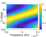
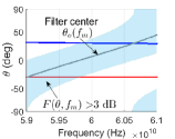
The term represents the frequency-spatial filter response that results from the superposition of the TTD sub-arrays, uniformly separated in phase, space and time. The filter is centred at angle , which corresponds to the gain maximizing trajectory about which the filter’s spatial response is symmetric, and can be obtained by solving , , as follows:
| (12) |
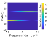
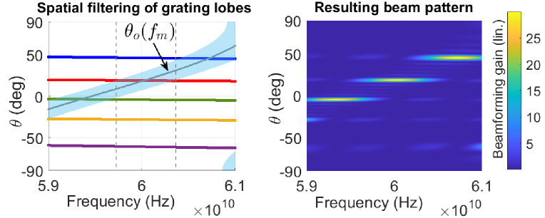
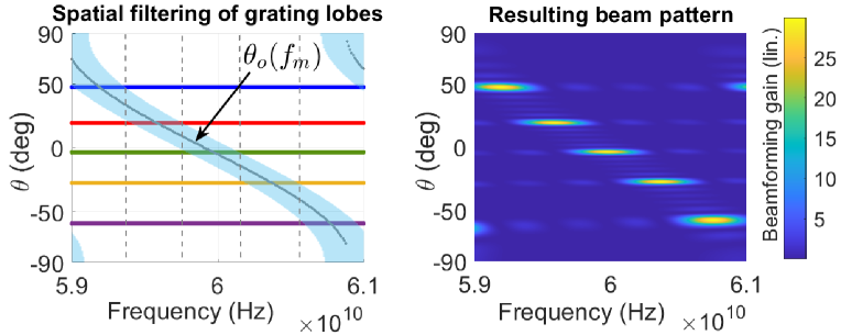
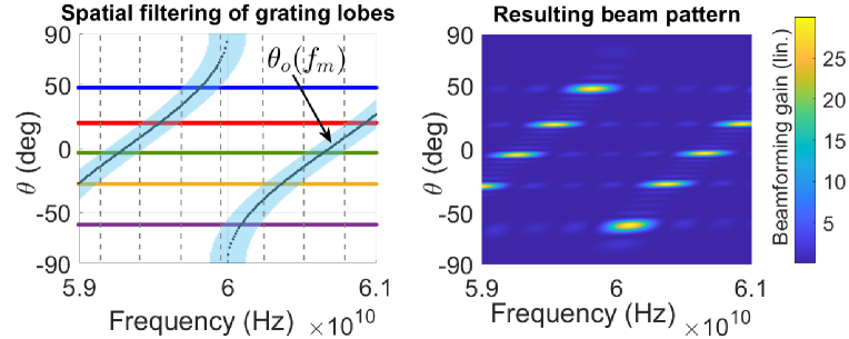
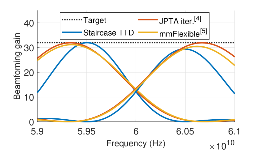
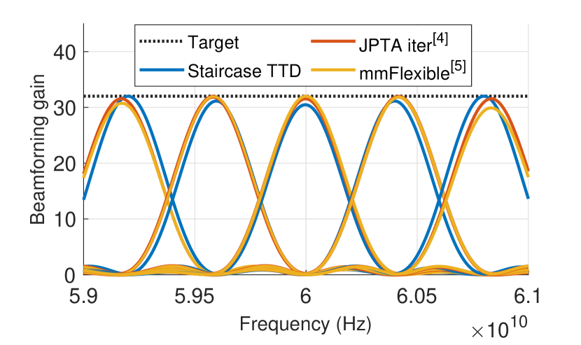
The step delay makes the filter’s spatial response frequency-dependent as seen in Fig. 4(a). This is reminiscent of dispersive rainbow beam codebooks constructed using uniform TTD arrays in [9, 6, 7, 8]. Further, the 3dB angular width of the filter for a given is given by [10, Chapt 22.7]. Thus, for each frequency, the filter retains beam patterns corresponding to roughly one spectral segment of angular width out of the spectral copies present in the parent beam-pattern as shown in Fig. 4(b,d), thereby resulting in the sub-band-specific spatial responses shown in Fig. 4(c,e). Through the systematic design of grating lobe parameters (, , ) and filter parameters (, ), we can achieve the required directional sub-band-specific beams.
IV Two-stage design of sub-band-beams
In this section, we propose the two-stage design of the Staircase codebook parameters , , , and defined in (4) and (5), to construct sub-band-specific beams to simultaneously communicate with users located at sinusoidally equidistant angles in the sector , with uniform sub-band assignment to each user, as shown in Fig. 5(a). The UE angles are given as follows:
| (13) |
IV-A Sub-band beam design with uniform Staircase codebooks
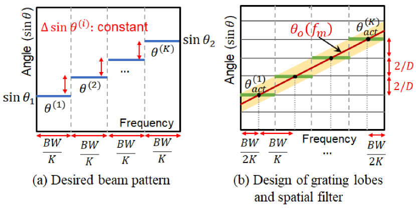
Stage I: The first step towards designing the required beam pattern is constructing directional grating lobes exactly at the required angles in (13), as shown in Fig. 5(b). We know that the angular separation between adjacent grating lobes is , where is the step size of the uniform Staircase codebook. Hence, in order to fit exactly grating lobes in , we must select as the smallest integer satisfying , where is the beam-squint222Upon setting , all spectral copies except the first copy at , exhibit beam-squint. Hence, the angular separation between the first and grating lobes is where correction factor. Thus, can be computed as follows:
| (14) |
Further, setting and creates grating lobes at , given as follows, out of which fall in the range .
| (15) |
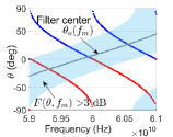
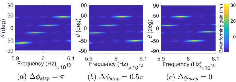
Stage II: The next step is to design the frequency-spatial filter to achieve the desired sub-band-specific filtering of the grating lobes as shown in Fig. 5(b). For given grating lobes at , the choice of filter parameters and determines the exact sub-band-angle mapping achieved, as is seen in the examples in Fig. 6. In order to ensure equal sub-bands that map to the angles , we need to design and in a manner as to make the filter-centre trajectory intersect the grating lobes at the centres of the respective sub-bands, as shown in Fig. 5(b).
For example, to achieve the beam pattern in Fig. 5(a), the first sub-band centred at must map to whereas the sub-band centred at must map to . Consequently, and 333 is obtained by solving in (12) with a substitution of from (16), which upon simplification gives (17). can be obtained as follows:
| (16) |
| (17) |
IV-B Mapping discrepancies with uniform Staircase codebooks
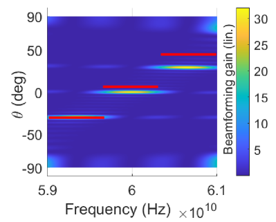
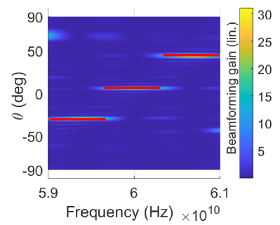
The first step to generating directional sub-band-specific beams mapped to angles as shown in (13), involves setting and . This results in grating lobes at angles as shown in (15). Since the uniform Staircase codebook constrains the (uniform) step-size to be an integer, designing as per (14) results in a mismatch or discrepancy between the target and actual angular levels, i.e. , as can be seen in Fig. 7(a), where the target sub-band-angle map is shown in red. This can be verified by substituting into (15) and comparing with (13). Thus, staircase TTD codebooks with uniform step-size suffer from mapping discrepancies which inhibit our ability to achieve the desired sub-band-angle map.
IV-C Alternative Staircase to overcome mapping discrepancies
In this section, we formulate a Staircase TTD codebook with non-uniform step-size, relaxing the requirement of being an integer. The uniform Staircase TTD codebook described in (4) and (5) can be visualized as having element-wise increments of with wrapping around by a magnitude of occurring at every array element satisfying . This wrapping around is triggered by the array index and results in a Staircase codebook with uniform integer step-size .
Instead, we can define a new Staircase TTD codebook where the wrapping around is triggered every time a certain magnitude threshold is exceeded, in the following manner.
| (18) | ||||
This new formulation results in a Staircase TTD codebook with non-uniform step-size. Thus, the parameter , which now controls only the angular spacing between grating lobes, is no longer constrained to be an integer, and can be selected as:
| (19) |
With , the actual grating lobes now coincide with the target angular levels , thereby resolving the mapping discrepancy as seen in Fig. 7(b).
Table I summarises the Staircase TTD codebook design to achieve sub-band-specific beams shown in Fig. 5(a).
IV-D Constraints on achievable sub-band-angle mappings
The Staircase TTD codebook formulation described in Sec. IV-C can realize sub-band-beams that map to sinusoidally equidistant angles (13) in a specified sector in monotonically increasing () or monotonically decreasing () patterns. For a given array size , a sub-band angle map occupying the sector can be realized only if the following condition, which ensures that the array is large enough to induce wrapping around, holds:
| (20) |
Further, cyclic rotations of the monotonic sub-band-angle maps as shown in Fig. 8 are possible only when , and can be achieved by merely changing the filter parameter , keeping all other codebook parameters fixed. For example, we can map the first sub-band centred at to angle , by setting as .
V Numerical Results
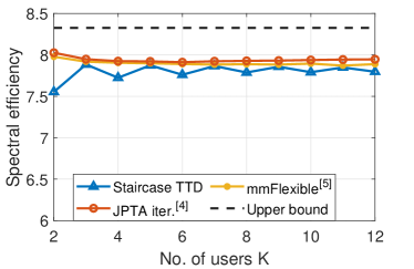
This section studies the performance of sub-band-beams designed using the Staircase TTD codebook for the system model described in Sec. II, in terms of the spectral efficiency of the BS and UE network. We present performance comparison with state-of-the-art methods, namely, the iterative weighted Least Squares optimization algorithm (JPTA iter.) presented in [4] with 20 training iterations, and the closed-form Least Squares solution (mmFlexible) proposed by [5]. All methods are compared with the theoretical upper bound represented by the ideal best-case beam. The BS operates at with subcarriers. We consider , , , and Signal-to-Noise Ratio (SNR) of , unless specified otherwise. Spectral efficiency results are averaged over all realizable beam patterns as per Table I for .
Fig. 9(a) studies spectral efficiency as a function of the number of users (or sub-bands), for . JPTA iter[4] performs the best for all , closely followed by mmFlexible[5]. For , Staircase TTD suffers noticeable degradation compared to JPTA iter and mmFlexible. However, as the number of users increases (), the performance of Staircase TTD matches up to that of JPTA iter and mmFlexible. This can be explained by studying the achieved beamforming gain sliced at the target angles (eqn. (13)), denoted by and defined as follows.
| (21) |
where is the beamforming gain function defined in (11). Fig. 10(a) and Fig. 10(b) depict the on-target beamforming gain for and users respectively, for . For , the average on-target gain achieved by Staircase TTD is lower than both mmFlexible and JPTA iter. However, when , Staircase TTD achieves comparable on-target gain to both mmFlexible and JPTA iter. This is because the beam design methodology of Staircase TTD, which involves aligning the on-target-gain maxima with the respective sub-band centres, is not target-gain optimal for smaller , and is hence outperformed by the optimization rooted mmFlexible and JPTA iter. However, a higher places stricter constraints on beam optimization, making the optimal solution converge to the beam design methodology of Staircase TTD as increases. This can be seen in Fig. 10(b), where Staircase TTD not only achieves comparable average on-target gain to JPTA iter and mmFlexible, but also has its gain maxima aligned with those of JPTA iter and mmFlexible when . This explains the observations made from Fig. 9(a).
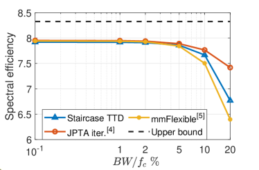
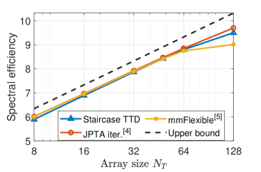
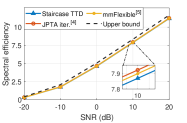
Fig. 9(b) and Fig. 9(c) study the effect of and BS array size , respectively, on the spectral efficiency for users. When , Staircase TTD achieves comparable performance to both JPTA iter and mmFlexible. For , Staircase TTD is seen to exhibit greater robustness to beam squint effects compared to mmFlexible, but is outperformed by JPTA iter. In Fig 9(c), Staircase TTD has comparable spectral-efficiency to both JPTA iter and mmFlexible for . Staircase TTD matches up to JPTA iter and considerably outperforms mmFlexible as increases thereafter. Fig. 9(d) shows that Staircase TTD achieves comparable performance to both JPTA iter and mmFlexible across SNRs for , , and GHz. Therefore, in summary, Staircase TTD achieves comparable performance to that of JPTA iter and mmFlexible when , and , while outperforming mmFlexible when and .
VI Future work
While this work focuses on analog codebook design for sub-band-beam synthesis and theoretical performance evaluation in terms of spectral efficiency, our future work would study the practical challenges in RF front-end design to enable the prescribed sub-band-multiplexed multi-user data communication in realistic multi-user networks. In particular, we would study the impact of TTD hardware constraints, namely, delay range constraints [11], limited phase shifter resolution, and non-linearity of circuit delays [12], on the performance of sub-band-beams. In addition, a study of cross-sub-band interference and its mitigation is imperative for enabling sub-band-specific multi-user communication. Further, we would also study analog Staircase TTD codebooks with multi-stage frequency-spatial filtering, and multi-RF chain Staircase codebooks to realize beam patterns with arbitrary sub-band-angle mapping for highly flexible user-resource assignment.
VII Conclusions
This paper proposes a structured, closed-form design of analog TTD codebook based on dual-stage frequency-spatial filter design to realize directional sub-band-beams to support simultaneous multi-user data communication. By implementing sub-band-selective filtering of directional grating lobes, it achieves beams with the required sub-band-angle mapping. It also delineates constraints on achievable sub-band-angle maps using the proposed codebook. The proposed method, besides espousing a conceptual visualization of sub-band-beam design, presents a low-cost and low-complexity analog TTD codebook design that matches the performance of optimization-rooted state-of-the-art approaches in large networks and exhibits reasonable robustness to beam-squint at large bandwidths.
References
- [1] F. Boccardi, R. Heath, A. Lozano, T. Marzetta, and P. Popovski, “Five disruptive technology directions for 5g,” Communications Magazine, IEEE, vol. 52, 12 2013.
- [2] T. S. Rappaport, Y. Xing, G. R. MacCartney, A. F. Molisch, E. Mellios, and J. Zhang, “Overview of millimeter wave communications for fifth-generation (5g) wireless networks—with a focus on propagation models,” IEEE Transactions on Antennas and Propagation, vol. 65, no. 12, pp. 6213–6230, 2017.
- [3] J. G. Andrews, S. Buzzi, W. Choi, S. V. Hanly, A. Lozano, A. C. K. Soong, and J. C. Zhang, “What will 5g be?” IEEE Journal on Selected Areas in Communications, vol. 32, no. 6, pp. 1065–1082, 2014.
- [4] V. V. Ratnam, J. Mo, A. Alammouri, B. L. Ng, J. Zhang, and A. F. Molisch, “Joint phase-time arrays: A paradigm for frequency-dependent analog beamforming in 6g,” IEEE Access, vol. 10, pp. 73 364–73 377, 2022.
- [5] I. K. Jain, R. R. Vennam, R. Subbaraman, and D. Bharadia, “mmflexible: Flexible directional frequency multiplexing for multi-user mmwave networks,” arXiv preprint arXiv:2301.10950, 2023.
- [6] H. Yan, V. Boljanovic, and D. Cabric, “Wideband millimeter-wave beam training with true-time-delay array architecture,” in 2019 53rd Asilomar Conference on Signals, Systems, and Computers, 2019, pp. 1447–1452.
- [7] V. Boljanovic, H. Yan, E. Ghaderi, D. Heo, S. Gupta, and D. Cabric, “Design of millimeter-wave single-shot beam training for true-time-delay array,” in 2020 IEEE 21st International Workshop on Signal Processing Advances in Wireless Communications, 2020, pp. 1–5.
- [8] A. Wadaskar, V. Boljanovic, H. Yan, and D. Cabric, “3d rainbow beam design for fast beam training with true-time-delay arrays in wideband millimeter-wave systems,” in 2021 55th Asilomar Conference on Signals, Systems, and Computers, 2021, pp. 85–92.
- [9] V. Boljanovic, H. Yan, C.-C. Lin, S. Mohapatra, D. Heo, S. Gupta, and D. Cabric, “Fast beam training with true-time-delay arrays in wideband millimeter-wave systems,” IEEE Transactions on Circuits and Systems I: Regular Papers, vol. 68, no. 4, pp. 1727–1739, 2021.
- [10] S. J. Orfinidas, Electromagnetic Waves and Antennas, (accessed in Dec 1, 2019). [Online]. Available: http://eceweb1.rutgers.edu/~orfanidi/ewa/ewa-1up.pdf
- [11] E. Ghaderi, A. Ramani, A. Rahimi, D. Heo, S. Shekhar, and S. Gupta, “An integrated discrete-time delay-compensating technique for large-array beamformers,” IEEE Transactions on Circuits and Systems I: Regular Papers, vol. 66, pp. 1–11, 08 2019.
- [12] M.-K. Cho, I. Song, and J. D. Cressler, “A true time delay-based sige bi-directional t/r chipset for large-scale wideband timed array antennas,” in 2018 IEEE Radio Frequency Integrated Circuits Symposium (RFIC), 2018, pp. 272–275.