Rashba spin splitting based on trilayer graphene systems
Abstract
We establish a general Rashba Hamiltonian for trilayer graphene (TLG) by introducing an extrinsic layer-dependent Rashba spin-orbit coupling (SOC) arising from the off-plane inversion symmetry breaking. Our results indicate that the band spin splitting depends strongly on the layer-distribution and sign of Rashba SOC as well as the ABA or ABC stacking order of TLG. We find that spin splitting is significantly enhanced as the number of layers of the Rashba SOC with the same sign and magnitude increases. For the spatially-separated two Rashba SOCs of the same magnitude but the opposite sign, no spin splitting arises in ABC-TLG due to the preservation of inversion symmetry that ensures the complete cancellation of contributions from the opposite layers, whereas nonzero spin splitting is observed for ABA-TLG due to its own lack of inversion symmetry. We further illustrate that gate voltage is effective to modulate the spin-polarized states near the band edges. Moreover, we use density functional theory calculations to verify the Rashba splitting effect in the example of TLG interfaced by Au layer(s), which induce simultaneously the effective terms of Rashba SOC and gate voltage. Our results demonstrate the significance of layer and symmetry in manipulating spin and can be extended to multilayer graphene or other van der Waals interface systems.
I Introduction
Flat graphene in its natural state has no magnetism and negligible spin-orbit couplings (SOCs) CasNet ; KonGmi ; SiPra , resulting in its very limited application in spintronics despite its excellent mechanical, thermal and electronic properties CasNet ; NovFal . Because the spin degeneracy of electrons in graphene inhibits its development in spintronics, driving spin splitting has long been a key goal for scientists and engineers Yazyev ; PesMacs ; AvsTan ; HanKaw ; DayRay ; ZolGmi2020 ; AvsOch . In experiment, it is effective to open the spin degeneracy by inducing magnetism or SOCs in graphene with edge engineering Magda ; Slota , adatoms GonHer or proximity effect GhiKav ; AvsOch . For SOCs, it usually includes SieFab ; KanMe Rashba type, Ising type (valley-Zeemann term) and Kane-Mele type etc, among which Rashba SOC is easier to induce through interface engineering since only the off-plane () inversion symmetry ManKoo needs to be broken.
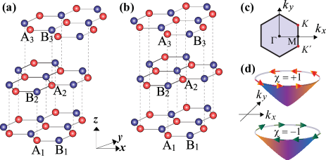
In recent years, numerous studies have been focused on the Rashba physics based on graphene monolayer, bilayer and multilayer DedFon ; Rashba ; MirSch ; MarVar2012 ; Zhai2014 ; WangKi ; ManKoo ; MarVar2016 ; FarTan ; KriGol ; YangLoh ; SinEsp ; LopCol ; PerMed ; GhiKav ; SieFab ; zhai2022 ; QiaoLi ; Hoque ; Khokh ; TiwSri ; LiZhang (see Table 1 for the experimentally-reported Rashba interface systems). The key electronic property induced by Rashba SOC is spin chirality in band (spin vortex in momentum space) Rashba ; Zhai2014 , which is an intriguing form of spin splitting. Remarkably, a large Rashba splitting up to 0.1 eV was experimentally achieved by contacting graphene with Au layer MarVar2012 , unlike graphene/Ni where magnetism is induced besides Rashba SOC DedFon ; PerMed . Inspiringly, room-temperature spin Hall effect induced by Rashba spin splitting has been observed in graphene-based heterostructures GhiKav2019 ; BenTor . Nevertheless, we have very little knowledge about the Rashba effect in trilayer graphene (TLG) till now, especially considering its stacking order, ABC type in Fig. 1(a) or ABA type in Fig. 1(b), between which significant differences exist in electrically-controllable electronic properties LuiLi ; BaoJing ; JhaCra ; KhoKhr , spin proximity effect ZolGmi2022 and second harmonics ShaLi .
| Interface systems | Strength () | Experiment | Theory |
| MLG/Ni(111) | meV | DedFon | PerMed |
| MLG/Au | 7-102 meV | MarVar2016 ; FarTan ; MarVar2012 | KriGol ; LopCol |
| MLG/MoTe2 | 2.5 meV | Hoque | Hoque |
| MLG/Bi0.3Sb1.7Te3 | 10 meV | Khokh | |
| BLG/WSe2 (biased) | 10-102 meV | TiwSri | |
| FLG/2H-TaS2 | 70 meV | LiZhang | LiZhang |
Here, we systematically study the Rashba spin splitting in TLG by establishing a general Hamiltonian with layer-dependent Rashba interaction induced by interface engineering ManKoo ; ZolGmi2020 ; DayRay ; AvsOch from the top or bottom sides of TLG. We show that the main factors affecting the band spin splitting are the layer distribution of Rashba SOC and the stacking order of TLG. In detail, the more layers the Rashba SOC of the same sign and magnitude exist, the larger the band splitting is. For a pair of Rashba SOCs with the opposite sign but the same magnitude, we find that no spin splitting happens in ABC-TLG since the inversion symmetry is not broken (resulting in the complete cancellation of contributions from the opposite layers), whereas spin splitting appears for ABA-TLG due to its own lack of inversion symmetry. We also illustrate that gate voltage can modulate the spin polarization by breaking the spin or energy degeneracy near the band edges. Furthermore, we use density functional theory (DFT) calculations KriGol ; zhai2022 to confirm the phenomena of Rashba spin splitting in TLG interfaced by Au layer(s), for which Rashba SOC and gate voltage work together.
Compared with Rashba bilayers zhai2022 , the Rashba trilayers we consider here have an additional middle layer that can be free from Rashba interaction and separates the top-bottom Rashba layers by a greater distance. Significantly, our results for TLG here reveal the nontrivial role of layer and symmetry in manipulating spin, applicable to not only TLG but also multilayers or other van der Waals materials. In addition, our results based on Rashba bilayers zhai2022 and trilayers reveal that an observable Rashba splitting can be induced without need of strictly controlling the number of graphene layers and the distribution uniformity between Rashba layers, facilitating wider applications of carbon films in spintronics.
We organize this article as follows. In Sec. II, we establish a general model Hamiltonian for Rashba trilayers within the framework of tight-binding approximation. In Sec. III, we present the results and discussion from the model. In Sec. IV, we show the concrete examples of trilayer Rashba TLG from DFT calculations. In Sec. V, other possible Rashba TLGs and device application are discussed. The last section is devoted to conclusion.
II General Model Hamiltonian
On basis of the tight-binding approximation Rashba ; KanMe , we begin with an empirical lattice Hamiltonian
| (1) |
where creates an electron with spin polarization at site on layer ( for bottom layer, middle layer and top layer, respectively), runs over all the nearest-neighbor-hopping sites, denotes spin up (down), is the spin Pauli operator, is the unit vector pointing from site to site . The parameter describes the intralayer nearest-neighbor hopping energy, is the -dependent Rashba spin-orbit energy, denotes the interlayer coupling energy between site on layer and site on layer (), indicates the effective layer-dependent potential induced by gate voltage, and denotes the on-site energy. The hopping parameter satisfies , where is the lattice constant and is the reduced Planck constant. For simplicity, we here mainly consider the interlayer nearest-neighbor interaction (), which roughly captures the main band features, while other longer-distance interlayer interactions are useful to modify the band edges JhaCra .
Corresponding to the five terms in Eq. (1) in order, we take with as the atomic basis set and perform the Fourier transformation CasNet ; KanMe , and then obtain the effective momentum-space Hamiltonian near the Fermi energy as
| (2) |
where the last term (nearly zero for bare TLG ZolGmi2022 ) depends on the interface details (see the example in Fig. 5, while we do not write specific expressions here) and contributes only to the diagonal term of the Hamiltonian, and the other terms are written as
| (3) |
where describes the momentum [ () as coordinate origin], represents valley (), is spin Pauli operator, is intralayer sublattice pseudospin Pauli operator, labels the identity matrix in the space, is the identity matrix in the layer pseudospin space. For each term in Hamiltonian (3), indicates the massless Dirac term ( is the Fermi velocity in monolayer graphene), denotes the interlayer nearest-neighbor coupling ( is the strength), represents the Rashba SOC ( is the strength), and represents the effective potential from gate voltage ( corresponds to the vertical bias). In particular, to facilitate the description of the layer pseudospin of trilayer graphene, we here employ the Pauli-like pseudospin matrices
where denotes in and in , and is for the ABC-stacking case and for the ABA-stacking case. To simplify the parameter description, we define and , where it satisfies and corresponding to Eq. (1). Without special instruction, a fixed value of is used below to perform model calculations, whereas the main conclusions (Abstract) do not depend on the choice of value.
It should be noted that a recent work by Zollner et al. have provided an effective Hamiltonian that includes additional proximity exchange and spin-orbit couplings in TLG-based van der Waals heterostructures ZolGmi2022 in addition to our concerned Rashba terms. There, the Rashba term is a perturbation term and our-of-plane spin polarization is focused. In contrast, we concentrate on the Rashba problem with respect to band spin chirality [Fig. 1(c)]. The core issue we are concerned about is the layer-dependent Rashba SOC, not only the amplitude, but more importantly the sign.
III Results and discussion from the model
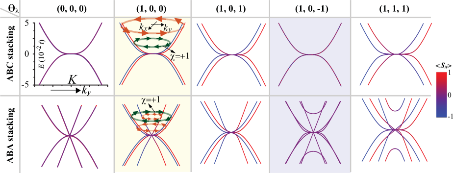
We start this section with two instructions below. Firstly, we consider the situation of spin splitting near the valley here, while the situation near the other valley can be achieved by time-reversal symmetry Zhai2014 . Secondly, we plot the energy bands along the direction and mainly calculate the average value of spin component , and schematically draw the chirality of spin vortex [as sketched in Fig. 1(d)] where appropriate. Note that it always satisfies , where is shown in Fig. 4 due to the necessity of analyzing the spin orientation. For simplicity, we here set —the unit of —to be 1.
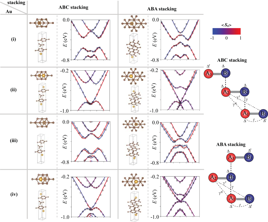
Without gate voltage, i.e. in model (1), we plot the low-energy band structures in Fig. 2 by using the Rashba parameter . For , and , it is seen that the number of subbands is doubled compared with , as expected from the traditional Rashba effect ManKoo . Judging from the strength of band spin splitting, we find that the more layers the Rashba SOC of the same sign and magnitude exist, the larger the band splitting is, independent of the stacking order. From the effect of band splitting, the Rashba effect localized in each layer can be equivalently considered to be equally divided by three layers through interlayer van der Waals coupling, similar to the previous finding in BLG zhai2022 . For the particular case —the spatially-separated two Rashba SOCs of the same magnitude but the opposite sign, no spin splitting occurs in ABC-TLG due to the complete cancellation of contributions from the opposite layers, whereas nonzero spin splitting is observed for ABA-TLG. Essentially, inversion symmetry is preserved for ABC-TLG, while ABA-TLG itself has no inversion symmetry even without the Rashba term. Note that the situation of here is shown only for comparison, while we mainly focus on the situations of where Rashba SOCs are induced by proximity effect from the top and bottom sides. As a result, the band spin splitting depends strongly on the layer-distribution and sign of Rashba SOC ) as well as the ABA or ABC stacking order of TLG. In other words, symmetry and stacking-order play a significant role in determining whether Rashba splitting exsits in energy band. Notably, the symmetry breaking here refers to the global structure rather than the local structure (the top or bottom interface).
Since we are mainly concerned with the electronic states near the Dirac point, we further use the Green’s function method ZhangSahu to obtain the effective Hamiltonian for the simple case in Fig. 2, where the last two terms in Eq. (1) are absent. For the TLG with ABC-stacking, a four-band effective Hamiltonian in basis {, , , } is obtained as
| (4) |
where is defined, has been defined below Eq. (3), and the orbit pseudospin operator and the spin operator read, respectively,
| (5) |
The term of in Eq. (4) agrees with the absence of spin splitting in Fig. 2 when inversion symmetry is not broken for . The magnitude of band spin splitting depends strongly on the value of , completely consistent with the calculations in Fig. 2.
For the TLG with ABA-stacking, an eight-band low-energy effective Hamiltonian in basis {, , , , , , , } is obtained as
| (6) |
where the different items are expressed as
| (7) |
Here, and describe the Rashba-modified monolayer-like and bilayer-like Hamiltonian CasNet , respectively; denotes the coupling between and . For the case of , we have , and , and therefore and return to the original forms of massless Dirac and massive parabolic dispersion BaoJing , whereas the nonzero modifies the Hamiltonian and induced Rashba splitting.
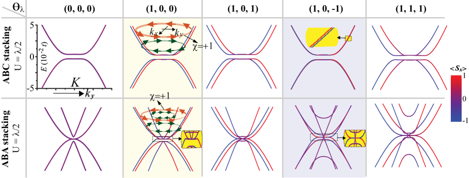
Then, we show the influence of gate voltage on band structure in Fig. 3 by fixing on basis of Fig. 2. For , it is seen that a band gap is opened in ABC-TLG, but semi-metallic property is preserved in ABA-TLG in spite of a local energy gap opened for the linear-dispersion Dirac cone, consistent with previous results LuiLi ; BaoJing . For , spin degeneracy is opened even though it is very weak (similar to the high-order perturbation effect in bilayer graphene zhai2022 ), because gate voltage breaks inversion symmetry in ABC-TLG.
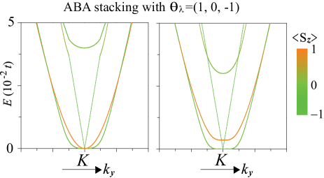
Regardless of spin degeneracy in Fig. 2 and Fig. 3, we notice that the spin-component average satisfies in the vicinity of valley (further calculations not shown here indicate that and ). This means that spin flipping happens when the electronic states go across valley . For ABA-TLG with , it is shown that (actually ) holds in Fig. 2 for , and becomes nonzero for in Fig. 3. To clarify the spin orientation for , we further plot the spin-component average of electronic states in conduction bands in Fig. 4. We find that holds, reflecting the spin signature dominated by the out-of-plane orientation in the situation of layered-opposite Rashba SOC zhai2022 .
In addition, we sketch the band spin chirality by taking as an example in Fig. 2 and Fig. 3 when the electron energy deviates from the neutral point (). It is seen that there is one subband with and one subband with for ABC-TLG, whereas the subband number with is one more than that with for ABA-TLG. It is expected that this difference should be identifiable from the spin Hall experiment GhiKav ; BenTor . The analysis of band spin chirality here is also applicable to other situations in Fig. 2 and Fig. 3.
IV Trilayer Rashba TLG from DFT calculations
| System | ABC-(i) | ABC-(ii) | ABC-(iii) | ABC-(iv) | ABA-(i) | ABA-(ii) | ABA-(iii) | ABA-(iv) | |
| (eV) | 2.572 | 2.386 | 2.569 | 2.423 | 2.576 | 2.489 | 2.528 | 2.461 | |
| (eV) | 0.325 | 0.384 | 0.369 | 0.385 | 0.321 | 0.275 | 0.322 | 0.221 | |
| (eV) | -0.192 | -0.216 | -0.237 | -0.279 | -0.183 | -0.212 | -0.229 | -0.192 | |
| (eV) | -0.144 | -0.167 | -0.158 | -0.164 | -0.148 | -0.165 | -0.159 | -0.167 | |
| (eV) | -0.050 | 0.086 | 0.076 | 0.086 | 0 | 0 | 0.168 | -0.160 | |
| (eV) | 0.027 | -0.023 | 0.083 | 0 | -0.082 | 0 | 0.135 | 0 | |
| (meV) | 43.4 | 43.2 | 93.6 | 93.3 | 43.2 | 42.9 | 93.2 | 92.8 | |
| (1,0,0) | (1,0,-1) | (1,0,0) | (1,0,-1) | (1,0,0) | (1,0,-1) | (1,0,0) | (1,0,-1) | ||
| (eV) | -0.261 | -0.003 | -0.202 | -0.003 | -0.281 | -0.305 | -0.258 | -0.301 | |
| (1,-0.75,-1) | (0,1,0) | (1,0.25,-1) | (0,1,0) | (1,-0.86,-1) | (0,1,0) | (1,0.67,-1) | (0,1,0) | ||
| (eV) | -0.505 | -0.832 | -0.502 | -0.861 | -0.494 | -0.865 | -0.616 | -0.702 |
By employing DFT calculations, we verify the Rashba spin splitting in model Hamiltonian (1) by contacting TLG with Au layer(s) from the top or bottom side(s), as an example but not limited to this example [see other candidates in Table (2)]. All the calculations are carried out using the VASP package Kres based on the first-principles plane wave pseudopotential method and density functional theory. The exchange correlation functional adopts the Perdew-BurkeErnzerhof (PBE) PerRu , the plane wave basis energy cutoff is set as 500 eV and the -points setup uses the Monkhorst-Pack scheme, with 15151 -point meshes. Geometric optimization is performed by electron relaxation, where the convergence value of energy is set as eV and the force of all atoms is less than 0.01 eV/nm. The unit cell has six C atoms and one (two) Au atom(s), and a vacuum region of 20 is used to avoid the interactions between neighboring slabs. The lattice parameter of graphene is a = 2.46 , with TLG interlayer distances of JhaCra . To better observe the Rashba splitting effect, we artificially set the spacing between Au atom and graphene layer at set as 2.7 (smaller than the equilibrium position ). Undoubtedly, the interlayer distance obtained from different experimental samples may vary KriGol , but the nature of Rashba induced band splitting will not be affected.
In Fig. 5, we show the DFT band structures for TLG in proximity with Au layer(s), where case (i) and case (iii) [case (ii) and case (iv)] are the single (dual)-interface situations, with the difference that cases (i) and case (ii) [case (ii) and case (iv)] correspond to the situation that Au atoms locate at the hexagonal centers (vertices) of their nearest-neighboring graphene layer. Our results indicate that the Rashba splitting indeed depends strongly on the stacking order and structural symmetry. For the same stacking order, case (iii) has larger splitting than case (i), as expected from Fig. 2. No spin splitting happens when inversion symmetry is preserved for case (ii) of ABC-TLG, likewise for case (iv) of ABC-TLG. To demonstrate the spin orientation, we also show by color in Fig. 5. It is worth nothing that for case (ii) and case (iv) of ABC-TLG is zero (opposite spin is mixed, resulting in spin degeneracy).
Furthermore, we fit the DFT results by the tight-binding model parameters, as listed in Table II. It is judged that the terms of Rashba SOC and gate voltage in model (1) are simultaneously induced. The Rashba term originates from the hopping between 5 orbital in Au atom and orbital in carbon atom KriGol . The chemical potential holds because there is electron transfer from Au atoms to carbon atoms. This charge transfer happens between the interlayer nearest-neighboring orbital hybridization of Au and carbon atoms. It is the potential energy difference between TLG layers that gives the origin of the effective gate-voltage term. Matching with the DFT data and tight-binding model, a more accurate effective Hamiltonian with a more extended form of orbital part is given as follows. For ABC stacking, we have
| (8) |
where , with (see Fig. 5 for hopping parameters , and ), , . For ABC stacking, we have
| (9) |
For the layer-related matrices in Eq. (8) and Eq. (9), all non-zero matrix elements are listed below
| (10) |
which are used to shorten the writing of formulas.
Besides the situations where Au atoms locate at the specific positions in Fig. 5, the model (1) that we build should be applicable in the other situations, for which the values of , and should be modified during model fitting. Conceivably, when magnetic interactions are further considered in complex interfaces zhai2022 ; ZolGmi2020 ; SieFab , more physics related to magnetism and topology can be achieved.
From the perspective of experimental feasibility, the freestanding form of the structures in Fig. 5 is still a challenge although is is theoretically possible. The existing reports indicate that graphene can indeed be embedded by Au atoms arranged in a monolayer structure, while additional substrate like Ni KriGol or Co Ryb2018 is needed to avoid the tendency of Au atoms to arrange in clusters. In actual operations, one can use SiO2 MarVar2016 , instead of Ni or Co, as the substrate or use bulk Au LeiTes2014 (viewed equivalently, due to the short-range nature of the proximity effect, only the surface Au monolayer works) to preserve the well-separated graphene states in Fig. 5 without the extra substrate-induced overlapping or hybridization effects.
V Other Possible Rashba TLGs and Device Application
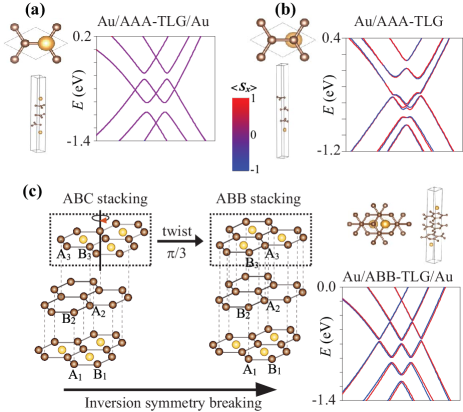
We notice that the experimental observation has shown that there is an additional AAA-stacking TLG configuration (simple hexagonal stacking) BaoYao , for which the electronic structure differ significantly from ABA-stacking and ABC-stacking. With this in mind, we perform further DFT calculations for Au/AAA-TLG in Fig. 6(a) and Au/AAA-TLG/Au in Fig. 6(b). The inversion symmetry is broken for the former but holds for the latter. As a result, no spin splitting is observed for Au/AAA-TLG/Au [], while spin splitting occurs for Au/AAA-TLG [].
Actually, many structural configurations different from ABA and ABC stacking for TLG can occur under artificial control, typically twisted-angle control LiZhang2022 ; DevLed . A notable recent theoretical work by Avisha et. al. has solved the problem of twisted TLG with Rashba SOC AviBand , where the Rashba trilayer Moiré lattice especially at small twisted angle ( is near ) is discussed, and as the twisted angle changes, the nonanalytic electronic charge density and the equilibrium spin currents are illustrated. Imaginably, the twist angle can easily alter or break the symmetry of untwisted parent structure. Based on these considerations, we choose a simpler case of twist-angle to discuss the problem, as shown in Fig. 6(c), where ABC stacking with inversion symmetry can become ABB stacking without inversion symmetry after the top layer is rotated. Notably, the TLG with ABB stacking does exist in the twist angle experimental samples LiZhang2022 ; DevLed . As expected, spin splitting happens for ABB stacking here, in stack contrast to ABC stacking (Fig. 5). Undoubtedly, Moiré patterns and flat bands under small twist angle should appear LiZhang2022 ; DevLed ; AviBand , but the Rashba splitting mechanism dictated by symmetry breaking should not be altered.
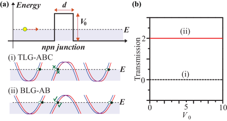
Moreover, it is necessary to discuss the difference between Rashba trilayer and Rashba bilayer in quantum transport from the perspective of device application. For simplicity, we here discuss the situation of low-energy effective models based on the analytical expressions in Sec. III. An junction is proposed in Fig. 7(a). As analyzed by the band-to-band tunnelling, the transport should be forbidden at normal incidence for TLG with ABC stacking because the incident and transmitted (scattering region) states are orthogonal Zhai2014 , resulting in zero transmission. For BLG with AB stacking, the complete transmission should happen at normal incidence because the incident and reflected states are orthogonal, resulting in Klein tunneling CasNet . As expected, the calculated transmission in Fig. 7(b) is independent of barrier height, holding for any in our calculations.
Essentially, the results in Fig. 7 are a manifestation of band topology characterized by the Berry’s (geometric) phase , defined by , where is the Berry connection for the wave function . Using the effective Hamiltonian in Eqs. (4)-(5) for Rashba TLG with ABC stacking, one can prove that changes from under to under . In comparison, changes from under to under for Rashba BLG Zhai2014 . This means, to observe Klein tunneling, should be an odd number CasNet ; Zhai2014 ; zhai2022 , which also applies to the situation of AAA or ABB stacking as well as the complex situation of TLG with ABA stacking when both the Dirac-like dispersion and the parabolic-like dispersion coexist.
VI Conclusions
By adding the layer-dependent Rashba interaction to the usual Hamiltonian of trilayer graphene, we have got four useful bits of information. First, the situation of band spin splitting in Rashba TLG is determined by the layer-distribution and sign of Rashba interaction and especially the stacking order. Second, the more layers the Rashba SOC of the same sign and magnitude exist, the larger the band splitting is. Third, for the spatially-separated two Rashba SOCs of the opposite sign but the same magnitude, no spin splitting happens in ABC-TLG with inversion symmetry while obviously weakened spin splitting is observed for ABA-TLG without inversion symmetry. Forth, gate voltage is helpful to modulate the spin splitting by opening the energy gaps in the vicinity of energy valleys. To confirm the phenomena of Rashba spin splitting, we have used DFT calculations in the platform of TLG interfaced by Au layer(s), which induce simultaneously the terms of Rashba SOC and gate voltage in TLG. Our results reveal the significance of layer and symmetry of TLG in manipulating spin and can be extended to other multilayer graphene or van der Waals quantum materials.
This work was supported by the NSFC with Grant No. 62374088 and No. 12074193.
References
- (1) A. H. Castro Neto, F. Guinea, N. M. R. Peres, K. S. Novoselov, and A. K. Geim, The electronic properties of graphene, Rev. Mod. Phys. 81, 109 (2009).
- (2) S. Konschuh, M. Gmitra, and J. Fabian, Band-structure topologies of graphene: Spin-orbit coupling effects from first principles, Phys. Rev. B 82, 245412 (2010).
- (3) J. Sichau, M. Prada, T. Anlauf, T. J. Lyon, B. Bosnjak, L. Tiemann, and R. H. Blick, Resonance microwave measurements of an intrinsic spin-orbit coupling gap in graphene: A possible indication of a topological state, Phys. Rev. Lett. 122, 046403 (2019).
- (4) K. S. Novoselov, V. I. Fal’ko, L. Colombo, P. R. Gellert, M. G. Schwab, and K. Kim, A roadmap for graphene, Nature 490, 192 (2012).
- (5) O. V. Yazyev, Emergence of magnetism in graphene materials and nanostructures, Rep. Prog. Phys. 73, 056501 (2010).
- (6) D. Pesin and A. H. MacDonald, Spintronics and pseudospintronics in graphene and topological insulators, Nat. Mater. 11, 409 (2012).
- (7) A. Avsar, J. Y. Tan, T. Taychatanapat, J. Balakrishnan, G. K. W. Koon, Y. Yeo, J. Lahiri, A. Carvalho, A. S. Rodin, E. C. T. O’Farrell, G. Eda, A. H. Castro Neto, and B. Özyilmaz, Spin-orbit proximity effect in graphene, Nat. Commun. 5, 4875 (2014).
- (8) W. Han, R. K. Kawakami, M. Gmitra, and J. Fabian, Graphene spintronics, Nat. Nanotechnol. 9, 794 (2014).
- (9) J.-F. Dayen, S. J. Ray, O. Karis, I. J. Vera-Marun, and M. V. Kamalakar, Two-dimensional van der Waals spinterfaces and magnetic-interfaces, Appl. Phys. Rev. 7, 011303 (2020).
- (10) K. Zollner, M. Gmitra, and J. Fabian, Swapping exchange and spin-orbit coupling in 2D van der waals heterostructures, Phys. Rev. Lett. 125, 196402 (2020).
- (11) A. Avsar, H. Ochoa, F. Guinea, B. Özyilmaz, B. J. van Wees, and I. J. Vera-Marun, Colloquium: Spintronics in graphene and other two-dimensional materials, Rev. Mod. Phys. 92, 021003 (2020).
- (12) G. Z. Magda, X. Jin, I. Hagymási, P. Vancsó, Z. Osváth, P. Nemes-Inczé, C. Hwang, L. P. Biró, and L. Tapasztó, Room-temperature magnetic order on zigzag edges of narrow graphene nanoribbons, Nature. 514, 608 (2014)
- (13) M. Slota, A. Keerthi, W. K. Myers, E. Tretyakov, M. Baumgarten, A. Keerthi, W. K. Myers, E. Tretyakov, M. Baumgarten, A. Ardavan, H. Sadeghi, C. J. Lambert, A. Narita, K. M’́ullen, and L. Bogani, Magnetic edge states and coherent manipulation of graphene nanoribbons, Nature. 557, 691 (2018).
- (14) H. González-Herrero, J. M. Gómez-Rodrĺguez, P. Mallet, M. Moaied, J. Jose Palacios, C. Salgado, M. M. Ugeda, J.-Y. Veuillen, F. Yndurain, and I. Brihuega, Atomic-scale control of graphene magnetism using hydrogen atoms, Science 352, 437 (2016).
- (15) T. S. Ghiasi, A. A. Kaverzin, A. H. Dismukes, D. K. de Wal, X. Roy, and B. J. van Wees, Electrical and thermal generation of spin currents by magnetic bilayer graphene, Nat. Nanotechnol. 16, 788 (2021).
- (16) J. F. Sierra, J. Fabian, R. K. Kawakami, S. Roche, and S. O. Valenzuela, Van der Waals heterostructures for spintronics and opto-spintronics, Nat. Nanotechnol. 16, 856 (2021).
- (17) C. L. Kane and E. J. Mele, Topological Order and the Quantum Spin Hall Effect, Phys. Rev. Lett. 95, 146802 (2005).
- (18) A. Manchon, H. C. Koo, J. Nitta, S. M. Frolov, and R. A. Duine, New perspectives for Rashba spin-orbit coupling, Nat. Mater. 14, 871 (2015).
- (19) A. M. Hoque, D. Khokhriakov, K. Zollner, B. Zhao, B. Karpiak, J. Fabian, and S. P. Dash, All-electrical creation and control of spin-galvanic signal in graphene and molybdenum ditelluride heterostructures at room temperature, Commun. Phys. 4, 124 (2021).
- (20) D. Khokhriakov, A. M. Hoque, B. Karpiak, and P. Dash, Gate-tunable spin-galvanic effect in graphene-topological insulator van der Waals heterostructures at room temperature, Nat. Commun. 11, 3657 (2020).
- (21) P. Tiwari, S. K. Srivastav, S. Ray, T. Das, and A. Bid, Observation of time-reversal invariant helical edge-modes in bilayer graphene/WSe2 heterostructure, ACS Nano 15, 916 (2021).
- (22) Y. S. Dedkov, M. Fonin, U. Rüdiger, and C. Laubschat, Rashba effect in the graphene/Ni(111) system, Phys. Rev. Lett. 100, 107602 (2008).
- (23) E. I. Rashba, Graphene with structure-induced spin-orbit coupling: Spin-polarized states, spin zero modes, and quantum Hall effect, Phys. Rev. B 79, 161409(R) (2009).
- (24) F. Mireles and J. Schliemann, Energy spectrum and Landau levels in bilayer graphene with spin-orbit interaction, New J. Phys. 14, 093026 (2012).
- (25) D. Marchenko, A. Varykhalov, M. R. Scholz, G. Bihlmayer, E. I. Rashba, A. Rybkin, A. M. Shikin, and O. Rader, Giant Rashba splitting in graphene due to hybridization with gold, Nat. Commun. 3, 1232 (2012).
- (26) Z. Qiao, X. Li, W.-K. Tse, H. Jiang, Y. Yao, and Q. Niu, Topological phases in gated bilayer graphene: Effects of Rashba spin-orbit coupling and exchange field, Phys. Rev. B 87, 125405 (2013).
- (27) X. Zhai and G. Jin, Reversing Berry phase and modulating Andreev reflection by Rashba spin-orbit coupling in graphene mono-and bilayers, Phys. Rev. B 89, 085430 (2014).
- (28) Z. Wang, D. K. Ki, H. Chen, H. Berger, A. H. MacDonald, and A. F. Morpurgo, Strong interface-induced spin-orbit interaction in graphene on WS2, Nat. Commun. 6, 8339 (2015).
- (29) D. Marchenko, A. Varykhalov, J. Sánchez-Barriga, Th. Seyller, and O. Rader, Rashba splitting of 100 meV in Au-intercalated graphene on SiC, Appl. Phys. Lett. 108, 172405 (2016).
- (30) E. C. T. O’Farrell, J. Y. Tan, Y. Yeo, G. K. W. Koon, B. Özyilmaz, K. Watanabe, and T. Taniguchi, Rashba interaction and local magnetic moments in a graphene-BN heterostructure intercalated with Au, Phys. Rev. Lett. 117, 076603 (2016).
- (31) M. Krivenkov, E. Golias, D. Marchenko, J. Sánchez-Barriga, G. Bihlmayer, O. Rader, and A. Varykhalov, Nanostructural origin of giant Rashba effect in intercalated graphene, 2D Mater. 4, 035010 (2017).
- (32) B. Yang, M. Lohmann, D. Barroso, I. Liao, Z. Lin, Y. Liu, L. Bartels, K. Watanabe, T. Taniguchi, and J. Shi, Strong electron-hole symmetric Rashba spin-orbit coupling in graphene/monolayer transition metal dichalcogenide heterostructures, Phys. Rev. B 96, 041409(R) (2017).
- (33) S. Singh, C. Espejo, and A. H. Romero, Structural, electronic, vibrational, and elastic properties of graphene/WS2 bilayer heterostructures, Phys. Rev. B 98, 155309 (2018).
- (34) A López, L Colmenárez, M Peralta, F Mireles, and E Medina, Proximity-induced spin-orbit effects in graphene on Au, Phys. Rev. B 99, 085411 (2019).
- (35) M. Peralta, E. Medina, and F. Mireles, Proximity-induced exchange and spin-orbit effects in graphene on Ni and Co, Phys. Rev. B 99, 195452 (2019).
- (36) X. Zhai, Layered opposite Rashba spin-orbit coupling in bilayer graphene: Loss of spin chirality, symmetry breaking, and topological transition, Phys. Rev. B 105, 205429 (2022).
- (37) L. Li, J. Zhang, G. Myeong, W. Shin, H. Lim, B. Kim, S. Kim, T. Jin, S. Cavill, B. S. Kim, C. Kim, J. Lischner, A. Ferreira, and S. Cho, Gate-Tunable Reversible Rashba-Edelstein Effect in a Few-Layer Graphene/2H-TaS2 Heterostructure at Room Temperature, ACS Nano. 14, 5251 (2020).
- (38) T. S. Ghiasi, A. A. Kaverzin, P. J. Blah, and B. J. van Wees, Charge-to-spin conversion by the Rashba-Edelstein effect in two-dimensional van der Waals heterostructures up to room temperature, Nano Lett. 19, 5959 (2019).
- (39) L. A. Benĺtez, W. S. Torres, J. F. Sierra, M. Timmermans, J. H. Garcia, S. Roche, M. V. Costache, and S. O. Valenzuela, Tunable room-temperature spin galvanic and spin Hall effects in van der Waals heterostructures, Nat. Mater. 19, 170 (2020).
- (40) C. H. Lui, Z. Li, K. F. Mak, E. Cappelluti, and T. F. Heinz, Observation of an electrically tunable band gap in trilayer graphene, Nat. Phys. 7, 944 (2011).
- (41) W. Bao, L. Jing, J. Velasco Jr, Y. Lee, G. Liu, D. Tran, B. Standley, M. Aykol, S. B. Cronin, D. Smirnov, M. Koshino, E. McCann, M. Bockrath, and C. N. Lau, Stacking-dependent band gap and quantum transport in trilayer graphene, Nat. Phys. 7, 948 (2011).
- (42) S. H. Jhang, M. F. Craciun, S. Schmidmeier, S. Tokumitsu, S. Russo, M. Yamamoto, Y. Skourski, J. Wosnitza, S. Tarucha, J. Eroms, and C. Strunk, Stacking-order dependent transport properties of trilayer graphene, Phys. Rev. B 84, 161408(R) (2011).
- (43) T. Khodkov, I. Khrapach, M. F. Craciun, and S. Russo, Direct observation of a gate tunable band gap in electrical transport in ABC-trilayer graphene, Nano Lett. 15, 4429 (2015).
- (44) K. Zollner, M. Gmitra, and J. Fabian, Proximity spin-orbit and exchange coupling in ABA and ABC trilayer graphene van der Waals heterostructures, Phys. Rev. B 105, 115126 (2022).
- (45) Y. Shan, Y. Li, D. Huang, Q. Tong, W. Yao, W. Liu, and S. Wu, Stacking symmetry governed second harmonic generation in graphene trilayers, Sci. Adv. 4, 0074 (2018).
- (46) F. Zhang, B. Sahu, H. Min, and A. H. MacDonald, Band structure of ABC-stacked graphene trilayers, Phys. Rev. B 82, 035409 (2010).
- (47) G. Kresse and J. Furthmüller, Efficient iterative schemes for ab initio total-energy calculations using a plane-wave basis set. Phys. Rev. B 54, 11169 (1996).
- (48) J. P. Perdew, A. Ruzsinszky, G. I. Csonka, O. A. Vydrov, G. E. Scuseria, L. A. Constantin, X. Zhou, and K. Burke, Restoring the density-gradient expansion for exchange in solids and surfaces. Phys. Rev. Lett. 100, 136406 (2008).
- (49) A. G. Rybkin, A. A. Rybkina, M. M. Otrokov, O. Yu. Vilkov, I. I. Klimovskikh, A. E. Petukhov, M. V. Filianina, V. Yu. Voroshnin, I. P. Rusinov, A. Ernst, A. Arnau, E. V. Chulkov, and A. M. Shikin, Magneto-spin-orbit graphene: interplay between exchange and spin-orbit couplings, Nano Lett. 18, 1564 (2018).
- (50) P. Leicht, J. Tesch, S. Bouvron, F. Blumenschein, P. Erler, L. Gragnaniello, and M. Fonin, Rashba splitting of graphene-covered Au(111) revealed by quasiparticle interference mapping, Phys. Rev. B 90, 241406(R) (2014).
- (51) C. Bao, W. Yao, E. Wang, C. Chen, J. Avila, M. C. Asensio, and S. Zhou, Stacking-dependent electronic structure of trilayer graphene resolved by nanospot angle-resolved photoemission spectroscopy, Nano Lett. 17, 1564 (2017).
- (52) Y. Li, S. Zhang, F. Chen, L. Wei, Z. Zhang, H. Xiao, H. Gao, M. Chen, S. Liang, D. Pei, L. Xu, K. Watanabe, T. Taniguchi, L. Yang, F. Miao, J. Liu, B. Cheng, M. Wang, Y. Chen, and Z. Liu, Observation of coexsiting dirac bands and Moiré flat bands in magic-angle twisted trilayer graphene, Adv. Mater. 34, 2205996 (2022).
- (53) T. Devakul, P. J. Ledwith, L.-Q. Xia, A. Uri, S. C. de la Barrera, P. Jarillo-Herrero, and L. Fu, Magic-angle helical trilayer graphene, Sci. Adv. 9, eadi6063 (2023).
- (54) Y. Avishai and Y. B. Band, Graphene bilayer and trilayer Moiré lattice with Rashba spin-orbit coupling, Phys. Rev. B 106, L041406 (2022).