Hierarchical meta-porous materials as sound absorbers
Abstract
The absorption of sound has great significance in many scientific and engineering applications, from room acoustics to noise mitigation.
In this context, porous materials have emerged as a viable solution towards high absorption performance and lightweight designs.
However, their performance is somehow limited in the low frequency regime.
Inspired by the concept of recursive patterns over multiple length scales typical of many natural materials, here, we propose a hierarchical organization of multilayered porous media and investigate their performance in terms of sound absorption.
Two types of designs are investigated: a hierarchical periodic and a hierarchical gradient.
In both cases it is found that the introduction of multiple levels of hierarchy allows to simultaneously (i) increase the level of absorption compared to the corresponding bulk block of porous material, along with (ii) a reduction of the quantity of porous material required.
Both the cases of normal and oblique incidences are examined.
The methodological approach is based on the transfer matrix method, optimization algorithms (metaheuristic Greedy Randomized Adaptive Search Procedure), and finite element calculations.
An excellent agreement is found between the analytical and the numerical simulations.
I Introduction
One of the stumbling blocks in modern acoustics is the absorption of the sound at the low frequencies, especially when the thickness of the absorbing structure is smaller than the wavelength of the incident sound wave.
This performance, highly desirable in most of the noise shielding applications related to human activities, is even more chased in contexts such as room acoustics, engine noise control, and, in general, where the space to host the absorber is limited [1].
In this context, porous materials have emerged as a viable solution towards high absorption performance and lightweight designs [2].
The main mechanism responsible for the sound absorption in porous media derives from the conversion of the sound energy into heat, further dissipated through the large number of complex micro-pores of which these materials are composed [3].
Several theoretical models to describe their acoustic behavior have been proposed, so far [4, 5, 6, 7, 8].
Among them, the Johnson-Champoux-Allard (JCA) model is probably the currently most widely used [8].
It describes the porous media through five physical parameters, namely: (1) the flow resistivity , (2) the open porosity , (3) the tortuosity , (4) the viscous characteristic length and (5) the thermal characteristic length .
Porous materials exhibit good absorption at the medium and high frequencies, whereas their performance is somehow limited in the low-frequency regime [2].
To overcome this deficiency without increasing their overall thickness, specific designs of porous materials, also known as meta-porous materials or porous metamaterials, have been recently proposed [9].
The most common approaches include:
(i) introducing resonators into the porous media generating additional peaks of absorption at the desired (low) frequencies of resonance of the resonators [10, 11, 12];
(ii) inserting a set of rigid partitions into the porous media responsible for the formation of multiple slow waves propagating over the full layer thickness.
This approach proved to be very effective in enhancing the absorption in the low frequency regime with respect to the corresponding block of bulk porous material, though deteriorating the performances in the middle and high frequencies [13, 14];
(iii) topological optimization of the porous materials including air cavities [15, 16] and micro-perforated panels [17, 18];
(iv) multi-scale design of porous materials with slits [19, 20] and holes [21] allowing for sound waves with longer wavelengths to enter into the material and get dissipated;
(iv) multilayered porous media (nowadays also known as meta-porous), whose overall dynamic performance strongly depends on the geometrical arrangement of the constituent elements.
Initiated in the early 90’s [22, 23, 24], the meta-porous approach is again gaining increasing interest into the scientific community due to the recent developments of the acoustic metamaterials [25, 26] and fabrication techniques [27], which have allowed for the conception of new designs more and more optimized [28, 29] for an efficient and broadband sound attenuation at the low frequencies using moderate amounts of absorbing materials [9].
In this context, Jimenez et al. [30] proposed an optimized chirped multilayered porous material exhibiting enhanced low frequency absorption (compared to that of the corresponding bulk porous material of the same length).
The sound absorption and transmission of the system have been theoretically analyzed, revealing unidirectional performances, given the broken geometrical symmetry introduced by the chirped design.
Optimized layers of porous materials have also shown the possibility of reaching perfect and broadband sound absorption [31].
In this case, the performance enhancement derived from the impedance matching of the meta-porous to the incoming wave.
Almeida et al. [32] have investigated a multilayered porous material with slit-type perforations organized according to the Cantor set, i.e., exhibiting a fractal porosity.
A broadband and efficient absorption performance in the low-frequency regime was reported.
Despite the large number of meta-porous designs proposed so far, enhancing the absorption performance at low frequencies of these materials remains an open research issue.
In this context, the concept of hierarchy, borrowed from Nature, has recently emerged as a promising source of inspiration for the engineering of metamaterials with complex structural architectures leading to advanced functional properties in several research fields, from electromagnetism to elasticity and acoustics [33, 34, 35, 36].
Hierarchical architectures, which can be defined as recursive structural patterns repeated at different length scales, are widespread in Nature being a developmental outcome of coping with evolutionary challenges and often bring to enhanced and functional-oriented properties compared to simpler structural organizations [37].
Initially mainly investigated in the quasi-static domain, hierarchical architectures have recently gained increasing interest also in dynamics and in acoustic metamaterials.
For instance, Li et al. [38] showed that adding surface porosity and unit cell heterogeneity in a multi-scale structure inspired by the cuttlefish bone allows for a broadband sound absorption and a higher deformation tolerance.
A spider-web-like organisation [39] or hierarchical honeycomb arrangements [40, 41] revealed to improve the bandgap properties, while acoustic metamaterials made of hierarchical membranes can reach unusual transmission loss characteristics [42].
A sandwich structure with hierarchical honeycomb interior has been shown to enhance the absorption in a much wider frequency range as compared to the regular sandwich [43].
Finally, labyrinthine fractal acoustic structures have recently shown increased low-frequency sound attenuation [44] and reflection [45].
Here we introduce the concept of hierarchical meta-porous materials, i.e., multilayered stacks of porous material and air, whose geometrical organizations describe a family of structures self-replicating (with or without exact self-similarity [46]) at different length scales (see Fig 1).
Through analytical calculations based on the transfer matrix method, optimization algorithms (metaheuristic Greedy Randomized Adaptive Search Procedure), and finite element simulations, we demonstrate the enhancement of the absorption coefficient as additional hierarchical levels are added into the porous layers(s).
Two types of organization are investigated, and their performance compared to that of the corresponding block of bulk material: a hierarchical periodic (HP) and a hierarchical gradient (HG).
In both cases it is found that the introduction of multiple levels of hierarchy simultaneously allows to (i) increase the level of absorption, and (ii) reduce the quantity of porous material required to achieve better performance.
Both the cases of normal and oblique incidences are examined.
The optimization procedure has been applied to maximize the absorption of the highest hierarchical level in the desired frequency range ([20, 2000] Hz), since for each proposed structure adding further hierarchical levels is always possible.
The paper is organized as follows: Section II is devoted to the description of the models and methods.
First, the hierarchical periodic and gradient periodic designs are introduced.
Then, the type of model adopted to describe the porous layers and the formalism used to calculate their absorption properties are provided.
Finally, the details of the optimization algorithm exploited to define the designs are given.
Section III reports the results for the cases of normal and oblique plane wave incidence, as well as the impact of the flow resistivity on the absorption coefficients.
Conclusions and further perspectives are given in Section IV.
II Models and methods
II.1 Hierarchical periodic and hierarchical gradient design
A great variety of biological systems exhibit a hierarchical organization, i.e., recursive geometrical patterns repeating at the micro- and/or macro-scale [47] scales. Hierarchy often derives from heterogeneity introduced in the form of (i) reinforcing elements (fibers, platelets, or crystals embedded in a softer matrix), (ii) voids, cavities, or canals into a matrix, and/or (iii) alternating layers of stiffer and softer materials. These diverse organizations can contribute to increased energy dissipation and crack deflection capabilities, toughness, resilience, but also to potentially affect the propagation of elastic waves or damping along with an overall mass density reduction [35]. Indeed, the evidence for a strong correlation between the propagation of waves and the micro-structure of the bio-composites hosting the propagation has been shown, connecting it to the hierarchical organization, often consisting of hard material building blocks embedded in a soft organic matrix, assembled in a hierarchical manner across multiple length scales [48]. Hierarchy can occur at different length scales, as in bones, nacre, or, at similar length scales, as in leaves, wood, corals, or sponges (porous materials) [49]. Electron microscope images of such hierarchical structures have often shown that their micro-structure appears not only to be self-similar but also periodic at each level of their structural hierarchy, such as in the case of enamel and dentine, protecting our teeth from failure after millions of times of mastication, or lobster cuticles, shrimp clubs, and crab claws exhibiting exceptional resistance to repeated dynamic attack either for preying or shielding purposes [50].
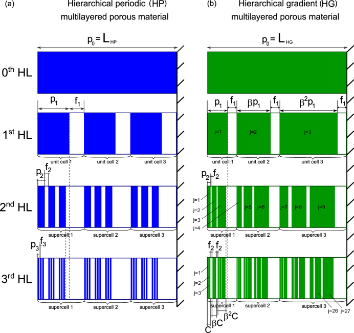
Inspired by these patterns, here we propose and investigate a multilayered porous media with a (i) hierarchical periodic (HP) and (ii) hierarchical gradient (HG) organization, as reported in Fig. 1(a) and Fig. 1(b), respectively.
In our case, the stiffer layers (colored in blue for the HP and in green for the HG) are made of porous material (melamine), whereas the softer ones (in white) of air.
In both cases, hierarchical levels (HL) are investigated, and the simplest organization, the hierarchical level, reduces to a bulk block of porous material of length (top panels of Fig. 1), where cm in the case of HP, and cm in the case of HG.
In the HP study case, the recursive rule adopted to build each next hierarchical level , with , is to divide the porous domain(s) of the previous level of length in unit cells (supercells) made of porous and air layers of length and , respectively.
For instance, the 1st hierarchical level is made of three unit cells of alternating porous and air layers of length and , such that .
In the same manner, the 2nd hierarchical level divides each porous domain of length of the 1st hierarchical level into three unit cells of alternating porous and air layers of length and , respectively, so that they form three supercells of total length .
Finally, the supercell of the last hierarchical level (3rd HL) consists of the following combination of alternating porous and air layers
.
The parameters and have been here arbitrarily chosen to be equal to 3 to maintain a good compromise between a sufficient high number of hierarchical levels explored and a limited total length of the structure.
Nevertheless, similar reasoning can be applied for higher or lower values of .
The thinnest porous layer thickness has been limited to at least 4 mm so that the JCA model properly describe its behaviour – see subsection II.2.
The lengths of the porous and fluid layers are determined as a result of an optimization procedure applied to the last hierarchical level – see Section II.4.
In the HG study case, the finite structures of each HL (other than the HL, which is a bulk block of porous material) are made of unit cells (supercells) constituted of porous and air layers, as in the HP case.
The difference, here, is that the three unit cells (supercells) belonging to the same HL exhibit different lengths according to the rule
| (1) |
where is a constant parameter (determined to be equal to 1.1085 by the optimization algorithm – see Section II.4), indicates the HL, the porous layer sequence number, the length of the first porous layer of the HL and indicates the integer part of the number included within the square brackets. The recursive rule to build each next hierarchical level , with , is to divide the porous domain(s) of the previous HL into porous and air layers keeping the proportions of the previous HL constants, i.e., maintaining the ratio constant. More qualitatively, the process can be described as taking all the porous and fluid layers of the whole structure of the HL and squeeze them successively into the lengths corresponding to those of the porous layer(s) of the 1st HL (minus the length(s) of the last fluid layer(s) of the 2nd to the HL(s)) to form the up to porous layers of the successive HL (in this recursive formula the indices always refer to the HL). For instance, the 1st hierarchical level is made of unit cells of alternating porous and air layers of lengths , such that . In the same manner, the 2nd hierarchical level divides each porous domain of the hierarchical level into alternating porous and air layers of lengths and , respectively, so that . Finally, the last HL (the 3rd one) appears to be constructed from the supercells in the following sequence
| (2) | |||
and how is illustrated in Fig. 1(b).
II.2 Modeling of the porous material
The porous layers are made of melamine, whose propagation of sound is described through the Johnson-Champoux-Allard (JCA) model [51]. The following parameters are adopted: porosity , tortuosity , viscous characteristic length m, thermal characteristic length m, and static air-flow resistivity Pa.s/m2 and Pa.s/m2 (chosen because of being representative of rather common porous media). The effective density and bulk modulus of the porous material are expressed as [51, 52]
| (3) | ||||
where is the Biot frequency, , [53] is the thermal resistivity [54] and the correction functions are given by [55, 7]
| (4) | ||||
where kPa is the atmospheric pressure, and the parameters of air (which is assumed to be the fluid present in the pores) are given by: kg/m3 (density of the air), Pr (Prandtl number), (heat capacity ratio) and kg/(ms) (air viscosity). Once these parameters determined, the wavenumber and the effective acoustic impedance can be obtained.
II.3 Calculation of the absorption coefficient
A harmonic plane wave with time dependence incident on the rigidly backed multilayered hierarchical structures is considered. The transfer matrix formalism is adopted. The transfer matrix of each layer can be defined as
| (5) |
where is the length of the corresponding layer, is the projection of the wavenumber perpendicular to the layers, is the impedance, is the angle of the incident plane wave considered. The subscripts p and 0 indicate if the property refers to the porous or fluid (air) layer, respectively. The total transfer matrix of the hierarchical level is the consecutive product of the transfer matrices of each layer
| (6) |
The reflection coefficient is obtained as follows
| (7) |
and the absorption determined as .
II.4 Optimization of the geometry
For the sake of comparison of the absorption performances of the multilayered structures as additional hierarchical levels are introduced, the absorption coefficient of the highest hierarchical level (3rd one in our case) is optimized by minimizing the area above the absorption curve in the desired frequency range [20, 2000] Hz.
This strategy has been chosen because for a given multilayered structure additional hierarchical levels can always be added.
Once the geometrical parameters of the highest hierarchical level are determined (lengths and of the porous and air layers), those of the previous levels can be recursively derived – see Section II.1.
The optimization algorithm adopted is based on the resolution scheme of the metaheuristic Greedy Randomized Adaptive Search Procedure (GRASP [56]).
A solution is constructed, without backtracking, in a very short time (between 1.8 and 2.0 s).
According to the type of structure to optimize (HP or HG), a large variety of solutions is obtained through a randomized exploration of the greedy algorithm which assigns values to the variables describing the lengths of the porous ( in the HP and in the HG) and fluid () layers, the number of hierarchical levels , the number of unit cells (supercells) , and/or the evolution coefficient (this last one concerning the HG study case, only).
Restricted by practical requirements, the aforementioned parameters were bounded to mm, mm, , in the optimization procedure.
The obtained solutions are then sorted based on a best absorption criterion, which forms the objective function.
The final parameters for the HP organization are: cm, mm, mm, mm, mm.
Those for the HG multilayered structure are: cm mm, mm, mm, mm and .
The sizes are rounded up to mm.
III Results
III.1 Periodic hierarchical material
Normal incidence
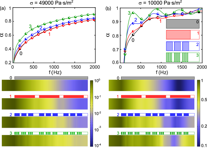
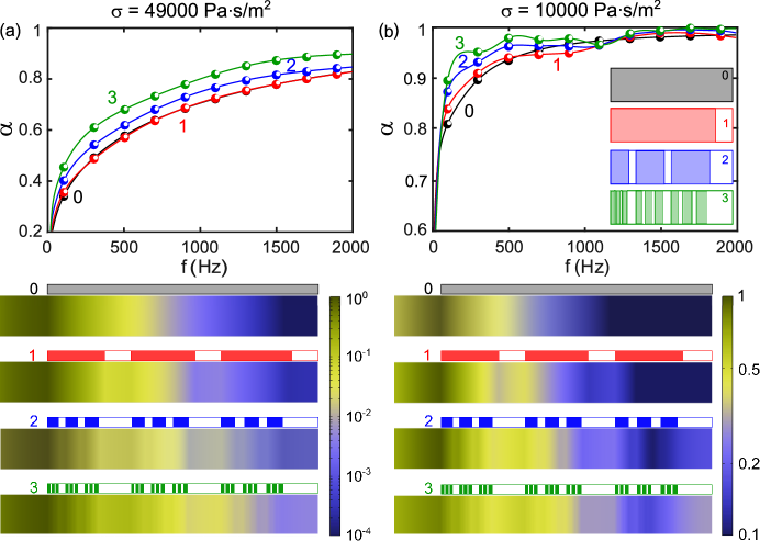
Figure 2 reports the absorption coefficient as a function of the frequency (top panels) and the normalized total pressure fields at 900 Hz (bottom panels) for the HP study case.
The comparison includes three hierarchical levels besides the case of bulk block of porous material (0th HL) for different values of (49000 Pa.s/m2 in Fig. 2(a) and 10000 Pa.s/m2 in Fig. 2(b), respectively).
The sketch of a unit cell / supercell of each hierarchical level is shown in the inset of Fig. 2(b).
A plane wave normally incident from the left side of the structures is considered.
The results, issued from the transfer matrix method described in the previous Sections II.2 and II.3, are reported as continuous colored lines (black for the 0th HL, red for the 1st HL, blue for the 2nd HL, and green for the 3rd HL).
The absorption coefficients are calculated also numerically through finite element methods using the Acoustics module of Comsol Multi-physics, and reported as colored circular markers (also in this case in black for the 0th HL, red for the 1st HL, blue for the 2nd HL, and green for the 3rd HL).
A perfect agreement is found over the whole frequency range [20 2000] Hz.
Top panels of Fig. 2(a) and Fig. 2(b) clearly show that the introduction of hierarchy brings to a considerable enhancement of the absorption properties of the structure, regardless the chosen value of (49000 Pa.s/m2 or 10000 Pa.s/m2), but for the first iteration (0th HL 1st HL), where the variation of is minimal.
The introduction of additional HLs in porous media with large values of , top panel of Fig. 2(a), brings to a progressive increase of the absorption coefficient (going up to a maximum enhancement of 39% at = 75 Hz and between 20% and 25% when 200 Hz when the 3rd HL is compared to the bulk block of porous material – 0th HL) over the whole considered frequency range.
Similarly, when smaller values of are considered, top panel of Fig. 2(b), the introduction of hierarchy still remains advantageous, especially at the low frequencies, although the enhancement of the absorption coefficient has now an oscillating behaviour reaching a 20% enhancement at = 330 Hz (where an absorption peak deriving from the resonance is expected).
The % of absorption enhancement reduces going towards higher frequencies.
Finally, to get further insight on the possible reason producing the observed increase of the absorption coefficient as additional hierarchical levels are added, the normalized total acoustic pressure fields for the 3rd HL at = 900 Hz (where the most pronounced peak of the green curve in Fig. 2(b) occurs) are reported in the lower panels of Fig. 2.
The disposal of the porous layers with respect to the whole multilayered structures is plotted above each pressure distribution.
From these plots it clearly emerges that introducing additional hierarchical levels allows the pressure field to propagate further inside the hierarchical meta-porous, which in turn can explain the higher values of .
The main physical mechanism taking place seems to be related to the fact that hierarchy, alternating porous and air layers at different length scales, increases its absorption efficiency by trapping the waves inside the air gaps.
Specifically, in the case of smaller value of , the introduction of additional hierarchical levels allows the incident field to propagate further within the sample and to increase the absorption values related to the first quarter-wavelength resonance (around 330 Hz) and to the higher order resonances – Fig. 2(b).
On the contrary, when larger values of are considered, the field decreases rapidly inside the structure becoming very weak at the rigid end and not allowing for any noticeable geometrical resonances – Fig. 2(a).
Oblique incidence
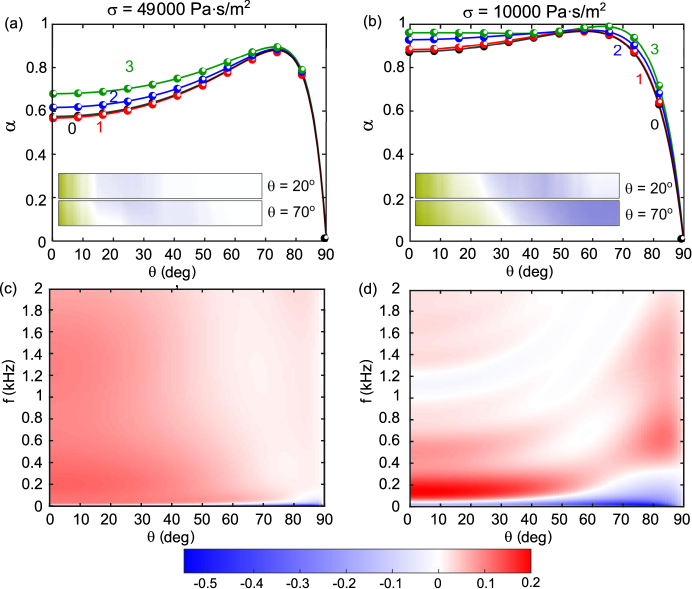
The absorption performance depends on the angle of incidence of the plane wave impinging the hierarchical meta-porous under consideration, as clearly evident from Eq. 5.
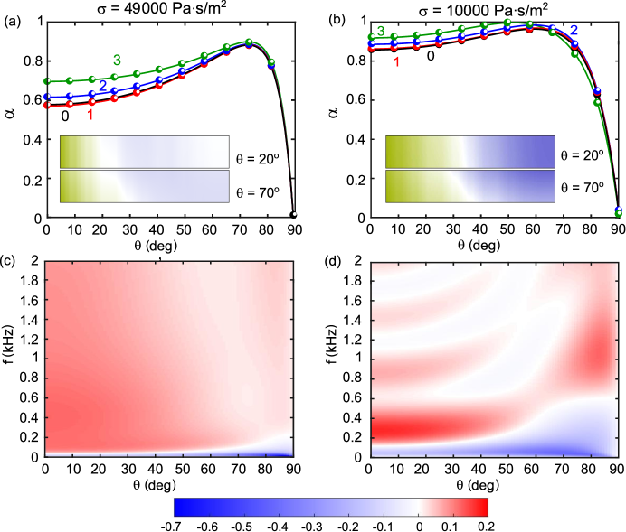
Figure 3(a) and Fig. 3(b) report the absorption coefficient at 500 Hz as a function of [0, 90]∘ for the three hierarchical levels and the bulk block of porous material.
Also in this case, two values of are considered (49000 Pa.s/m2 and 10000 Pa.s/m2, respectively).
The results, issued from the transfer matrix method (continuous colored lines) and finite element-based numerical simulations (circular colored markers), clearly show that the hierarchical design is advantageous, in terms of absorption, for most of the angles of incidence, namely when = 49000 Pa.s/m2 and when = 10000 Pa.s/m2.
For larger angles of incidence, the absorption curves almost merge and go to 0 when .
The largest enhancement between the bulk block of porous material (0th HL) and the highest HL considered (3rd HL) is observed at normal incidence (), for both the values of , although it reaches 20% and 10% for the larger and smaller values of , respectively.
It is worth reminding here that the geometry was only optimized for normal incidence, i.e., , which, in our opinion, makes the potential of the hierarchical design remarkable since it remains advantageous also for most of the remaining angles.
The normalized total acoustic pressure fields for the 3rd HL at different angles of incidence ( and ) are also reported as insets in Fig. 3(a) and Fig. 3(b).
The pressure levels reach much higher values inside the structures composed of porous with lower values of , allowing for the more efficient absorption.
What happens in the remaining frequencies can be deduced from Fig. 3(c) and Fig. 3(d), which report the maps of the difference between the absorption coefficient of the 3rd HL and of the 0th HL in the space for = 49000 Pa.s/m2 and 10000 Pa.s/m2, respectively.
The color map has been chosen so that the regions where no enhancement of the absorption was observed (when the hierarchical design is introduced), appear in white, whereas the regions where the hierarchy outperforms (under-performs) the bulk block porous layer are in dark red (blue).
In this sense larger values of seem to be more beneficial in the overall range of parameters, though for certain regions the smaller value of provides larger values of .
Influence of the flow resistivity
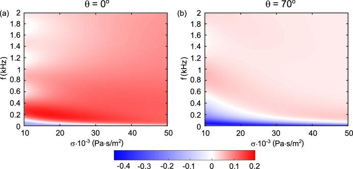
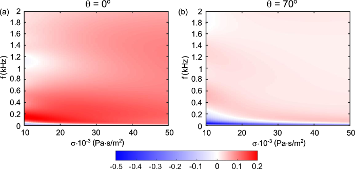
Finally, the behaviour of is reported in Fig. 4(a) and Fig. 4(b) as a function of the frequency and of the flow resistivity , when and (the range 10000 - 50000 Pa.s/m2 for has been considered since it corresponds to common values of porous media used in practical applications). The same color map described above applies. Therefore, we can infer that, when normal incidence is considered, Fig. 4(a), the enhancement of the absorption coefficient introduced by the hierarchical design (3rd HL compared to the bulk block of porous material) increases as the value of increases (except a narrow low frequency region). When = 70∘ is considered, Fig. 4(b), the frequency region within which the hierarchical design under-performs the bulk block of porous material slightly increases, especially at the lower frequencies.
III.2 Gradient hierarchical material
Normal incidence
Following the same approach described in the previous Section, meta-porous with a hierarchical gradient (HG) organization, as the ones reported in Fig. 1(b), are considered. First, the absorption coefficient as a function of the frequency and the normalized total pressure fields at 600 Hz are reported in the top and bottom panels of Fig. 5, respectively. As in the HP case, three HLs and the bulk block of porous material are compared when = 49000 Pa.s/m2, Fig. 5(a), and when = 10000 Pa.s/m2, Fig. 5(b). The results are qualitatively and quantitatively very similar to those of the HP organization (compare Fig. 2 and Fig. 5). In both plots the absorption coefficient benefits from the introduction of hierarchy, though its oscillating behaviour when = 10000 Pa.s/m2, Fig. 5(b), is smoother. The total pressure field maps at Hz, where we observe a peak of the green curve in Fig. 5, are reported in the lower panel. Increasing the number of HLs, the wave field propagates over a longer distance inside the material, and, thus, the wave interacts with multiple porous layers to get highly absorbed. When = 10000 Pa.s/m2, the quarter-wavelength (around 200 Hz) and higher order resonances take place. Also in this case, the hierarchy seems to get these peaks more pronounced.
Oblique incidence
The dependence of on the angle of incidence is investigated and reported at = 500 Hz in Fig. 6(a) and Fig. 6(b) for = 49000 Pa.s/m2 (a) and Pa.s/m2, respectively.
Again, the introduction of hierarchy clearly shows a higher absorption coefficient in most of the angles of incidence (for both large and small values of ), exhibiting a peak of absorption around 73∘.
The pressure fields for and are reported in the insets of Fig. 6(a) and Fig. 6(b).
Their behaviour is very similar to those of the HP counterpart.
Figure 6(c) and Fig. 6(d) report the maps of the difference between the absorption coefficient of the 3rd HL and of the 0th HL in the space for = 49000 Pa.s/m2 and 10000 Pa.s/m2, respectively.
Contrary to the HP case, when the HG organization is considered, a significant reduction of the low-frequency region where the hierarchical design was under-performing with respect to the bulk block is observed.
Influence of the flow resistivity
Finally, the behaviour of as a function of the frequency and of the flow resistivity for and is shown in Fig. 7(a) and Fig. 7(b), respectively. Most of the combinations show that the introduction of the hierarchy is beneficial in terms of absorption. The overall increase of is more consequent in the case of normal incidence (being twice larger than for = 70∘ at the peak values).
IV Conclusions
We have theoretically and numerically investigated the absorption coefficient of hierarchical meta-porous media made of alternating melamine and air layers. Two designs have been considered: a hierarchical periodic and a hierarchical gradient. Both structures exhibit advantageous absorbing properties in the [20, 2000] Hz frequency range compared to a block of porous material of the same length. A maximum enhancement of 39% was observed in the hierarchical periodic organization. Remarkably, the hierarchical geometries, optimized for a single value of flow resistivity and for normal wave incidence, only, remain advantageous designs exhibiting higher absorption in a wide range of (angle of incidence of the plane wave) and (air flow resistivity). Specifically, when large values of are considered, a gradual increase of the absorption coefficient as additional hierarchical levels are added, has been observed for both the periodic and gradient designs. The performance enhancement is still kept when smaller values of are concerned, observing an oscillating increase of the absorption coefficient with higher peak values. The largest enhancement of the absorption coefficient is observed at normal incidence. The proposed hierarchical meta-porous revealed to be a promising design for increasing the low-frequency sound absorption in porous media.
Acknowledgements. S.K., B.D. and M.M. acknowledge the EU, H2020 FET Open BOHEME: Bio-Inspired Hierarchical Metamaterials (grant number 863179).
References
- [1] Bies DA, Hansen CH, Howard CQ. 2017 Engineering noise control. CRC press.
- [2] Cao L, Fu Q, Si Y, Ding B, Yu J. 2018 Porous materials for sound absorption. Composites Communications 10, 25–35.
- [3] Wang Y, Wang Y, Xu J, Yu H, Zhang C, Ren L. 2021 Broadband low-frequency sound absorption by coiled-up space embedded in a porous layer. Applied Acoustics 182, 108226.
- [4] Biot MA. 2005 Theory of Propagation of Elastic Waves in a Fluid‐Saturated Porous Solid. I. Low‐Frequency Range. The Journal of the Acoustical Society of America 28, 168–178.
- [5] Biot MA. 1956 Theory of propagation of elastic waves in a fluid-saturated porous solid. II. Higher frequency range. The Journal of the acoustical Society of america 28, 179–191.
- [6] Allard JF, Aknine A, Depollier C. 1986 Acoustical properties of partially reticulated foams with high and medium flow resistance. The Journal of the Acoustical Society of America 79, 1734–1740.
- [7] Johnson DL, Koplik J, Dashen R. 1987 Theory of dynamic permeability and tortuosity in fluid-saturated porous media. Journal of fluid mechanics 176, 379–402.
- [8] Jiménez N, Umnova O, Groby JP. 2021 Acoustic waves in periodic structures, metamaterials, and porous media. Ch. the Transfer Matrix Method in Acoustics, Springer International Publishing, Cham pp. 103–164.
- [9] Gao N, Zhang Z, Deng J, Guo X, Cheng B, Hou H. 2022 Acoustic metamaterials for noise reduction: a review. Advanced Materials Technologies 7, 2100698.
- [10] Groby JP, Lagarrigue C, Brouard B, Dazel O, Tournat V, Nennig B. 2015 Enhancing the absorption properties of acoustic porous plates by periodically embedding Helmholtz resonators. The Journal of the Acoustical Society of America 137, 273–280.
- [11] Lagarrigue C, Groby JP, Tournat V, Dazel O, Umnova O. 2013 Absorption of sound by porous layers with embedded periodic arrays of resonant inclusions. The Journal of the Acoustical Society of America 134, 4670–4680.
- [12] Zhu XF, Lau SK, Lu Z, Jeon W. 2019 Broadband low-frequency sound absorption by periodic metamaterial resonators embedded in a porous layer. Journal of Sound and Vibration 461, 114922.
- [13] Yang J, Lee JS, Kim YY. 2015 Metaporous layer to overcome the thickness constraint for broadband sound absorption. Journal of Applied Physics 117.
- [14] Yang J, Lee JS, Kim YY. 2016 Multiple slow waves in metaporous layers for broadband sound absorption. Journal of Physics D: Applied Physics 50, 015301.
- [15] Li D, Chang D, Liu B. 2017 Enhanced low-to mid-frequency sound absorption using parallel-arranged perforated plates with extended tubes and porous material. Applied Acoustics 127, 316–323.
- [16] Liu X, Yu C, Xin F. 2021 Gradually perforated porous materials backed with Helmholtz resonant cavity for broadband low-frequency sound absorption. Composite Structures 263, 113647.
- [17] Toyoda M, Sakagami K, Okano M, Okuzono T, Toyoda E. 2017 Improved sound absorption performance of three-dimensional MPP space sound absorbers by filling with porous materials. Applied Acoustics 116, 311–316.
- [18] Liu Z, Zhan J, Fard M, Davy JL. 2017 Acoustic measurement of a 3D printed micro-perforated panel combined with a porous material. Measurement 104, 233–236.
- [19] Xin F, Ma X, Liu X, Zhang C. 2019 A multiscale theoretical approach for the sound absorption of slit-perforated double porosity materials. Composite Structures 223, 110919.
- [20] Attenborough K. 2021 Analytical approximations for sub wavelength sound absorption by porous layers with labyrinthine slit perforations. Applied Sciences 11, 3299.
- [21] Atalla N, Panneton R, Sgard F, Olny X. 2001 Acoustic absorption of macro-perforated porous materials. Journal of sound and vibration 243, 659–678.
- [22] Lauriks W, Mees P, Allard JF. 1992 The acoustic transmission through layered systems. Journal of sound and vibration 155, 125–132.
- [23] Brouard B, Lafarge D, Allard JF. 1995 A general method of modelling sound propagation in layered media. Journal of Sound and Vibration 183, 129–142.
- [24] Dunn I, Davern W. 1986 Calculation of acoustic impedance of multi-layer absorbers. Applied acoustics 19, 321–334.
- [25] Craster RV, Guenneau S. 2012 Acoustic metamaterials: Negative refraction, imaging, lensing and cloaking vol. 166. Springer Science & Business Media.
- [26] Romero-Garcia V, Hladky-Hennion AC. 2019 Fundamentals and applications of acoustic metamaterials: from seismic to radio frequency. John Wiley & Sons.
- [27] Ghaffari Mosanenzadeh S, Naguib HE, Park CB, Atalla N. 2015 Design and development of novel bio-based functionally graded foams for enhanced acoustic capabilities. Journal of materials science 50, 1248–1256.
- [28] Zhang X, Qu Z, Wang H. 2020 Engineering acoustic metamaterials for sound absorption: From uniform to gradient structures. Iscience 23, 101110.
- [29] Roca D, Cante J, Lloberas-Valls O, Pàmies T, Oliver J. 2021 Multiresonant Layered Acoustic Metamaterial (MLAM) solution for broadband low-frequency noise attenuation through double-peak sound transmission loss response. Extreme Mechanics Letters 47, 101368.
- [30] Jiménez N, Romero-García V, Cebrecos A, Picó R, Sánchez-Morcillo VJ, Garcia-Raffi LM. 2016 Broadband quasi perfect absorption using chirped multi-layer porous materials. AIP Advances 6, 121605.
- [31] Jiménez N, Romero-García V, Groby JP. 2018 Perfect absorption of sound by rigidly-backed high-porous materials. Acta Acustica united with Acustica 104, 396–409.
- [32] Almeida GdN, Vergara EF, Lenzi A, Alves ÁS, de Jesus JC. 2023 Low-frequency broadband sound absorption based on Cantor fractal porosity. Journal of Applied Physics 133.
- [33] Song GY, Cheng Q, Huang B, Dong HY, Cui TJ. 2016 Broadband fractal acoustic metamaterials for low-frequency sound attenuation. Applied Physics Letters 109, 131901.
- [34] Mousanezhad D, Babaee S, Ebrahimi H, Ghosh R, Hamouda AS, Bertoldi K, Vaziri A. 2015 Hierarchical honeycomb auxetic metamaterials. Scientific reports 5, 1–8.
- [35] Miniaci M, Krushynska A, Gliozzi AS, Kherraz N, Bosia F, Pugno NM. 2018 Design and fabrication of bioinspired hierarchical dissipative elastic metamaterials. Physical Review Applied 10, 024012.
- [36] Dal Poggetto VF. 2023 Bioinspired acoustic metamaterials: From natural designs to optimized structures. Frontiers in Materials 10, 1176457.
- [37] Lakes R. 1993 Materials with structural hierarchy. Nature 361, 511–515.
- [38] Li X, Yu X, Zhao M, Li Z, Wang Z, Zhai W. 2023 Multi-Level Bioinspired Microlattice with Broadband Sound-Absorption Capabilities and Deformation-Tolerant Compressive Response. Advanced Functional Materials 33, 2210160.
- [39] Ruan H, Li D. 2022 Wave Propagation Properties of a Spider-Web-Like Hierarchical Acoustic Metamaterial. physica status solidi (b) p. 2200341.
- [40] Sun P, Zhang Z, Guo H, Liu N, Jin W, Yuan T, Wang Y. 2022 Topological optimization of hierarchical honeycomb acoustic metamaterials for low-frequency extreme broad band gaps. Applied Acoustics 188, 108579.
- [41] Ma N, Han Q, Han S, Li C. 2023 Hierarchical re-entrant honeycomb metamaterial for energy absorption and vibration insulation. International Journal of Mechanical Sciences 250, 108307.
- [42] Edwards WT, Chang CM, McKnight G, Sorensen A, Nutt SR. 2020 Transmission loss and dynamic response of hierarchical membrane-type acoustic metamaterials. Journal of Vibration and Acoustics 142, 021007.
- [43] He W, Peng X, Xin F, Lu TJ. 2022 Ultralight micro-perforated sandwich panel with hierarchical honeycomb core for sound absorption. Journal of Sandwich Structures & Materials 24, 201–217.
- [44] Man X, Xia B, Luo Z, Liu J, Li K, Nie Y. 2021 Engineering three-dimensional labyrinthine fractal acoustic metamaterials with low-frequency multi-band sound suppression. The Journal of the Acoustical Society of America 149, 308–319.
- [45] Krushynska A, Bosia F, Miniaci M, Pugno N. 2017 Spider web-structured labyrinthine acoustic metamaterials for low-frequency sound control. New Journal of Physics 19, 105001.
- [46] Mazzotti M, Foehr A, Bilal OR, Bergamini A, Bosia F, Daraio C, Pugno NM, Miniaci M. 2023 Bio-inspired non self-similar hierarchical elastic metamaterials. International Journal of Mechanical Sciences 241, 107915.
- [47] Fratzl P, Weinkamer R. 2007 Nature’s hierarchical materials. Progress in materials Science 52, 1263–1334.
- [48] Zhang P, To AC. 2013 Broadband wave filtering of bioinspired hierarchical phononic crystal. Applied physics letters 102.
- [49] Petkovich N, Stein A, Su B, Sanchez C, Yang X. 2012 Hierarchically Structured Porous Materials: From Nanoscience to Catalysis, Separation, Optics, Energy and Life Science. .
- [50] Weaver JC, Milliron GW, Miserez A, Evans-Lutterodt K, Herrera S, Gallana I, Mershon WJ, Swanson B, Zavattieri P, DiMasi E et al.. 2012 The stomatopod dactyl club: a formidable damage-tolerant biological hammer. Science 336, 1275–1280.
- [51] Allard J, Atalla N. 2009 Propagation of sound in porous media: modelling sound absorbing materials. John Wiley & Sons.
- [52] De Ryck L, Groby JP, Leclaire P, Lauriks W, Wirgin A, Fellah ZEA, Depollier C. 2007 Acoustic wave propagation in a macroscopically inhomogeneous porous medium saturated by a fluid. Applied physics letters 90.
- [53] Champoux Y, Allard JF. 1991 Dynamic tortuosity and bulk modulus in air-saturated porous media. Journal of applied physics 70, 1975–1979.
- [54] Groby JP, Dazel O, Duclos A, Boeckx L, Kelders L. 2011 Enhancing the absorption coefficient of a backed rigid frame porous layer by embedding circular periodic inclusions. The Journal of the Acoustical Society of America 130, 3771–3780.
- [55] Allard JF, Champoux Y. 1992 New empirical equations for sound propagation in rigid frame fibrous materials. The Journal of the Acoustical Society of America 91, 3346–3353.
- [56] Feo TA, Resende MG. 1995 Greedy randomized adaptive search procedures. Journal of global optimization 6, 109–133.