Tracking and fast imaging of a translational object via Fourier modulation
Abstract
The tracking and imaging of high-speed moving objects hold significant promise for application in various fields. Single-pixel imaging enables the progressive capture of a fast-moving translational object through motion compensation. However, achieving a balance between a short reconstruction time and a good image quality is challenging. In this study, we present a approach that simultaneously incorporates position encoding and spatial information encoding through the Fourier patterns. The utilization of Fourier patterns with specific spatial frequencies ensures robust and accurate object localization. By exploiting the properties of the Fourier transform, our method achieves a remarkable reduction in time complexity and memory consumption while significantly enhancing image quality. Furthermore, we introduce an optimized sampling strategy specifically tailored for small moving objects, significantly reducing the required dwell time for imaging. The proposed method provides a practical solution for the real-time tracking, imaging and edge detection of translational objects, underscoring its considerable potential for diverse applications.
I Introduction
The precise tracking and imaging of fast-moving objects hold tremendous promise for application across various domains, including navigation, biomedical research, and computer vision. The development of high-speed cameras has been instrumental, enabling the capture of moving objects at exceptionally high frame rates while maintaining a relatively high signal-to-noise ratio. However, the cost, data flux, and operation band associated with these cameras limit their application. Single-pixel imaging (SPI) Edgar, Gibson, and Padgett (2019), as an emerging imaging technology, has several key advantages, including low-cost data transmission, widely applicable spectrum, high detection sensitivity, and more. SPI requires a considerable number of modulation patterns for image reconstruction. Unfortunately, the refresh rate of the spatial light modulator (SLM) employed to modulate is limited. When the object moves at high speed, acquiring sufficient measurements within a single motion frame becomes challenging. This can result in image degradation, blurring, or even ineffective imaging.
There are two primary approaches to achieving the SPI of moving objects. One involves enhancing the modulation speed, while the other focuses on initially estimating the motion parameters of the object and subsequently applying motion compensation. Enhancing modulation speed can be achieved through various methods, such as using LED-based illumination Huang et al. (2022), mechanical translating masks Jiang et al. (2020), spinning masks Hahamovich et al. (2021); Jiang et al. (2021), or swept aggregate patterns Kilcullen, Ozaki, and Liang (2022). These methods can achieve higher modulation rates compared to the commonly used Digital Micro-mirror Device (DMD). However, they often face challenges in improving spatial resolution. Moreover, when tracking an object, additional algorithms are required to process the obtained sequence of motion frames. In the case of translational objects, where the object’s shape and size remain unchanged during motion, there is data redundancy in these captured image frame sequences.
The motion parameter estimation approaches primarily deal with translational objects and employ a range of techniques, including algorithm estimation Zhang, Gong, and Han (2013); Jiao et al. (2019), the projection-slice theorem Jiang et al. (2017); Shi et al. (2019); Yang et al. (2022a), low-resolution image correlation calculations Sun et al. (2019); Monin, Hahamovich, and Rosenthal (2021); Wu, Hu, and Wang (2021), Fourier patterns Zhang et al. (2019); Dan, Liu, and Gao (2022); Li et al. (2023), geometric moment patterns Zha et al. (2021); Xiao et al. (2022); Guo et al. (2022); Zhang et al. (2023), two-dimensional projective patterns Yang et al. (2022b), laterally shifting patterns Sun et al. (2022), and four-quadrant detector Du et al. (2023) to measure object displacement. Motion compensation is then applied to the imaging patterns, and object reconstruction is achieved using compressed sensing algorithms Li et al. (2013) or ghost imaging Ferri et al. (2010) algorithms. Among these methods, Fourier patterns-based approaches excel in reliably capturing relative displacements at high frame rates but may not provide absolute positions. Geometric moment-based tracking methods generally offer the highest tracking frame rates, but they exhibit lower noise robustness compared to Fourier patterns-based methods in obtaining crucial relative position data for image reconstruction Li et al. (2023). Moreover, most of the imaging patterns used in these approaches are either random patterns or Hadamard patterns. After motion compensation, using fast inverse transformations for image reconstruction may not be feasible. Consequently, a trade-off must be made between reconstruction time and quality, limiting their applicability in real-time imaging scenarios.
In this study, we present an approach for achieving high-frame-rate tracking, fast imaging and edge detection of a translational object. The proposed approach employs Fourier patterns not only for encoding the position of the object but also for encoding its spatial distribution. The utilization of Fourier patterns with specific spatial frequencies can ensure robust and accurate object localization. This, in turn, enables us to apply phase correction to the acquired Fourier coefficients and employ the fast Fourier transform (FFT) to reconstruct images and edges of the moving object. We demonstrate this experimentally by fast-tracking and imaging a real translational object. Additionally, we introduce an optimized sampling strategy for small objects and validate it by monitoring an object that quickly passes through the field of view (FOV).
II Method
II.1 Tracking and imaging
The Fourier single-pixel imaging (FSI) Zhang, Ma, and Zhong (2015); Zhang et al. (2017a) leverages Fourier patterns to sequentially encode spatial information from objects into time signals collected by a bucket detector and restores the image using the FFT. Various Fourier patterns with distinct spatial frequencies (, ) are employed to acquire the Fourier coefficients in the Fourier transform domain. Two widely used methods for obtaining these coefficients in FSI are the four-step and three-step phase-shifting methods. In the four-step phase-shifting method, four Fourier patterns, each with the same spatial frequency but different initial phases (0, , , and ), are utilized to capture a Fourier coefficient. The corresponding measurement values are denoted as , , , and . The Fourier coefficient () is given by
| (1) |
Similarly, the three-step phase-shifting method involves using three Fourier patterns with the same spatial frequency but initial phases of 0, , and , respectively. The measured values corresponding to these three patterns are represented as , , and . The Fourier coefficient () can be determined using the following equation:
| (2) |
According to the translation property of the Fourier transform, the displacement of a translational object in the spatial domain will result in a phase shift in the Fourier domain, which can be expressed as
| (3) | |||||
where denotes the Fourier spectrum of the original object , and represents the inverse Fourier transform. The displacements in the X and Y directions can be calculated by measuring the two Fourier coefficients and of each motion frame, which only contains one spatial frequency or . Finally, the displacements in one direction, for example X-direction, between the frame and the initial frame can be calculated as follows:
| (4) | |||||
where denotes the argument operation, represents the Fourier coefficient obtained at the initial position, and represents the Fourier coefficient obtained at the current motion frame. and are the corresponding phase angles of the Fourier coefficient. and are the calculated coordinates obtained from the corresponding Fourier coefficients. Similarly, the relative displacement in the -direction of the object in the frame, as well as the coordinate , can also be determined. The acquired coordinates (, ), relative to the object’s position, remain unchanged during translation. Consequently, these coordinates can serve as valuable feature points for object tracking. The phase variation of the Fourier coefficient caused by motion in the frame can be corrected as follows:
| (5) |
As illustrated in Fig. 1(a), our proposed pattern sequence is exclusively composed of Fourier patterns and is divided into two components: tracking patterns and imaging patterns. The tracking patterns remain consistent across all motion frames, comprising six frames generated using the three-step phase-shifting method. These patterns correspond to spatial frequencies and , where and represent the number of pixels in the X and Y directions, respectively. In contrast, the imaging patterns for each motion frame vary and are chosen based on the spatial frequency’s position within the Fourier spectrum. If necessary, the imaging patterns can be constructed using either a three-step or four-step phase-shifting method.
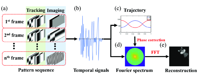
After tracking the trajectory of the object (Fig. 1(c)) and subsequently calculating the displacement from the initial position, the Fourier coefficients of the object are phase-corrected at each spatial frequency based on Eq. (5), as shown in Fig. 1(d). The object image can be obtained via FFT from the corrected Fourier spectrum, as illustrated in Fig. 1(e).
II.2 Edge detetion
The edge image of a moving object can be derived using phase-corrected Fourier spectrum. This involves utilizing the Sobel operator for edge detection. The resulting edge image, denoted as , is calculated as follows:
| (6) |
Here, represents the phase-corrected Fourier spectrum, while and correspond to the Fourier transforms of the Sobel operators in two different directions. To address any issues related to matrix size mismatch, it’s important to note that the Sobel operators of size are zero-padded to match the dimensions of the obejct image before undergoing the Fourier transform, as explained in Ref. Wu et al., 2024.
II.3 Sampling strategies for imaging
Imaging patterns are determined based on the spatial frequency positions within the Fourier spectrum. The fundamental approach follows a circular order Zhang et al. (2017b) and is referred to as the sequential sampling strategy. This strategy is not contingent on the size of the object. However, given that objects are typically much smaller than the FOV, this sampling method may result in reduced imaging efficiency. In scenarios where the FOV has an even number of pixels in both directions, and the object’s size within the X and Y dimensions occupies less than half of it, we employ an alternative strategy. This strategy involves selecting imaging patterns at regular intervals within the Fourier spectrum, corresponding to spatial frequencies such as and , where M and N denote the number of pixels in the and directions, respectively. This approach is referred to as the interval sampling strategy. By using such patterns, an image containing four objects can be generated, one of which represents the actual object. Subsequently, the image with dimensions of pixels can be determined by the tracked coordinates of the object at its initial position.
III Simulation
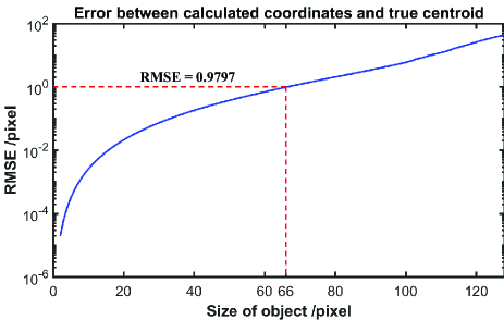
Previously, Fourier patterns-based tracking methods are limited to providing only the relative position of a moving object, lacking the capability to achieve absolute position tracking. In a system featuring an pixel resolution, we use Fourier patterns with a spatial frequency of for tracking. The calculated coordinates (, ) by Eq. 4, relative to the object’s position, remain unchanged during translation. Consequently, these coordinates can serve as valuable feature points for object tracking. Moreover, when dealing with small moving objects, such as those sized at , the calculated tracking coordinates closely approximate the centroid coordinates of the object. We demonstrate this by simulation. Specifically, we employed 800 grayscale images from the DIV2K dataset Agustsson and Timofte (2017), scaling them to various dimensions and positioning them as virtual objects within a -pixel FOV. For tracking, we utilized Fourier patterns with a spatial frequency of . The the root-mean-square error (RMSE) is introduced to evaluate the accuracy of the calculated tracking coordinates. The RMSE of the calculated tracking coordinates and the centroid coordinates is defined as follows:
| (7) |
where represents the total number of virtual objects. The smaller the RMSE, the closer the calculated tracking coordinates is to the original centroid. As depicted in Fig. 2, when the object size falls below pixels, the RMSEs between the tracking coordinates and the image centroid coordinates remains below one pixel. Remarkably, across all sizes of the virtual objects, the calculated RMSE remained less than half of the object size, demonstrating that the calculated coordinates consistently fell within the boundaries of the virtual objects.
IV Experimental results
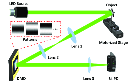
The experimental setup comprises several key components, including a high-power light-emitting diode (LED) source with a maximum output of 3.6 watts, a linear motorized stage (X-LSQ300B-E01, Zaber), a DMD (DLP7000, Texas Instruments), and a silicon-based photodetector (Si-PD, PDA100A2, Thorlabs), as illustrated in Fig. 3. Modulation patterns are preloaded onto the DMD in advance to facilitate modulation. The object is illuminated by the light source and subsequently imaged onto the DMD. Following modulation by the DMD, the modulated light is collected by the Si-PD and converted into measurable values through the data acquisition board (USB-6341, National Instruments). Notably, the DMD operates at a refresh rate of 20,000 Hz. The modulation patterns on the DMD have a pixel size of 256 x 256 pixels, where every 2 x 2 pixels are merged into a single superpixel. Consequently, the FOV has an image size of 128 x 128 pixels. The Fourier patterns employed in our method are binarized using the Sierra-Lite dithering algorithm Liang et al. (2019) with an upsampling ratio of 2.
IV.1 Tracking and imaging of a translational object
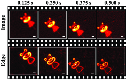
We first experimented to achieve rapid tracking and imaging of a translational object. In our experimental setup, we employed a total of 10 Fourier patterns for each motion frame. Among these, six Fourier patterns were utilized to determine the object’s position, while the remaining four were constructed using the four-step phase-shifting method to obtain a single Fourier coefficient of the object image within that frame. For the sake of comparison, we substituted the four Fourier patterns for imaging with four differential Hadamard patterns, a conventional method. Unlike our method of using phase correction, the conventional method necessitates compensating for imaging patterns by incorporating the relative displacement obtained through object tracking, thereby generating new measurement patterns. With the assistance of the differential ghost imaging (DGI) algorithm, this method utilizing Hadamard patterns, referred to as Had_DGI, swiftly computes the object’s image. In this experiment, we employed a dog toy as the object, with a motorized stage maintaining its cyclic translation at an average speed of within the FOV. We configured a total of 2,000 motion frames and utilized a total of 20,000 patterns, resulting in a measurement time of 1 second.
The FSI method, utilizing a modulation frequency of 1000 Hz, was employed to capture static images of the object both at its initial and farthest position. This enabled us to acquire the object’s reference image and its precise motion trajectory combining accurate displacement data from the motorized stage. Figure 4 demonstrates the motion of object, reconstructed images and edges at four different times (see supplementary material for a full video). With the progression of measurements, an increasing number of Fourier coefficients are acquired, leading to improved image clarity.
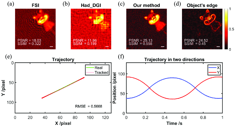
Figures 5(a-c) depict the final images obtained by FSI, Had_DGI, and our method, all conducted under the same modulation frequency and measurement time. Figures 5(d) shows the final edge image of the object restored by our method. To evaluate the quality of the reconstructed images, we employed the quantitative evaluators such as peak signal-to-noise ratio (PSNR) and structural similarity (SSIM). The PSNR between the original image and the reconstructed image is defined as
| (8) |
where represents the MSE between and . is the maximum value of the image data type. The larger the PSNR value, the higher the reconstruction quality. The SSIM between the original image and the reconstructed image is defined as
| (9) |
where represents the mean of , represents the variance of , represents the covariance of and , represents the mean of , represents the variance of , and are constants. The value range of SSIM is . The larger the SSIM value, the higher the structural similarity between the two images. The image quality achieved through our proposed method surpassed that attained with Had_DGI, both in visual appearance and quantitative assessments. Figure 5(e) showcases the comparison between the tracked trajectory and the actual trajectory. Our method exhibited remarkable accuracy, with an RMSE of 0.5668, closely approximating the real trajectory. Moreover, our proposed approach effectively calculated the trajectory in both the X and Y directions, providing a comprehensive view of the object’s acceleration and deceleration within the FOV during the measurement period, as demonstrated in Fig. 5(f).
IV.2 Monitoring of a fast-moving object with background
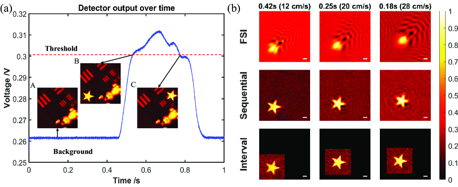
To demonstrate the robustness of our approach in handling complex scenarios and underscore the efficiency of our rapid imaging sampling technique for small moving objects, we devised an experiment involving a dynamic object amidst a cluttered background. The moving object was a pentagram constructed from white paper, which traversed the FOV swiftly, resulting in partial overlaps with background objects. Figure 6(a) displays the intensity readings captured at various time intervals during this process, as our motorized stage moved at a speed of , alongside three corresponding images. These images represent the background scene, the moment when the object fully entered the FOV, and the instant when the object began exiting the FOV, respectively. The moment the recorded light intensity surpasses the predefined threshold, it signifies the complete entry of the object into the FOV. Subsequently, the program controls the DMD to initiate the loading of the modulation pattern sequence until the object exits the FOV. Upon subtracting the previously recorded background data, the trajectory and image of the moving object can be restored using the resultant values. The Fourier patterns for imaging are constructed using the three-step phase-shifting method, meaning a total of nine detection patterns are required for each frame. Figure 6(b) illustrates the reconstructed images of the object at three distinct motion speeds, utilizing the FSI and our method with two different sampling strategies. These images were restored to their initial modulated positions. The motorized stage operated at speeds of , , and , equivalent to motion velocities of approximately 276, 460, and 644 pixels per second, respectively. The corresponding dwell times for the object when it was entirely within the FOV were 0.42 s, 0.25 s, and 0.18 s, respectively. Notably, our method outperforms FSI by successfully reconstructing moving object images at all three speeds. Specifically, the interval sampling strategy yields superior results, restoring finer details of the moving object. As the speed increases, the initial position of the object’s reconstructed image gradually shifts in the direction of motion. This phenomenon arises from the delay between detecting the object’s entry into the FOV and initiating pattern loading on the DMD. Consequently, higher speeds lead to greater object displacement during this delay period.
V Discussion
The proposed method offers key advantages compared to previous approaches based on motion compensation by using Fourier patterns and the FFT for imaging and edge detection, resulting in high-quality restored images and few computational time. Unlike previous techniques that relied on Hadamard patterns, our approach eliminates the need for storing motion-compensated imaging patterns. Moreover, we selected the Fourier patterns with specific spatial frequencies for determining the centroid of the moving object and to facilitate trajectory tracking, going beyond solely determining the relative positions. In comparison to the methods aimed at improving modulation speed, our approach can tracking fast-moving translational objects while concurrently achieving imaging and edge detection, thus obviating the need for post-processing the acquired image sequence. In our last experimental setup, we employed six modulation patterns for tracking and three modulation patterns for imaging. As a result, the maximum achievable frame rate using our method is limited by the refresh rate of the DMD, divided by nine. Utilizing a DMD with a refresh rate of 20,000 , we successfully attained a remarkable frame rate of 2222 Hz for tracking positions while effectively imaging the moving object. Additionally, the speed of image reconstruction is contingent on the time required for the FFT, aligning its time complexity with that of the FFT itself, enabling real-time imaging capabilities. The background noise in the obtained image can be mitigated further by deep learning-based denoisers Zhang, Zuo, and Zhang (2018); Zhang et al. (2021).
While the proposed method offers significant advantages, it is important to acknowledge its limitations. The imaging method applies only to translational objects with a simple background within the FOV as it relies on the characteristics of the Fourier transform. Thus, the proposed method is unsuitable for imaging objects that undergo rotation or deformation. Second, if the object’s residence time in the FOV is overly short, it may be difficult to acquire sufficient measurements for reconstructing high-quality images. This limitation can be improved by using a SLM with higher refresh rates.
VI Conclusion
In conclusion, we present a method that utilizes Fourier patterns for both position information encoding and spatial information encoding. Exploiting the unique characteristics of the Fourier transform, the proposed method achieves improved image quality and edge detection with low time complexity and minimal memory consumption of a translational object. Additionally, we solve the limitation of the Fourier pattern–based tracking method, enabling the determination of the locations of the object. Moreover, we present an interval sampling strategy specifically designed for small moving objects, which greatly reduced the required dwell time. The potential applications of the proposed method span various fields where the tracking and imaging of high-speed moving objects in real-time are essential. Future research can explore further strengthening and expanding this method to tackle challenges presented by complex environments, multiple objects, and objects undergoing rotation or deformation.
Acknowledgements.
The authors acknowledge Beijing Institute of Technology Research Fund Program for Young Scholars(Grant no.20212012) for financial support.Author Declarations
Conflict of Interest
The authors declare no conflict of interest to disclose.
Data Availability Statement
The data that support the findings of this study are available from the corresponding author upon reasonable request.
References
- Edgar, Gibson, and Padgett (2019) M. P. Edgar, G. M. Gibson, and M. J. Padgett, “Principles and prospects for single-pixel imaging,” Nature photonics 13, 13–20 (2019).
- Huang et al. (2022) H. Huang, L. Li, Y. Ma, and M. Sun, “25,000 fps computational ghost imaging with ultrafast structured illumination,” Electronic Materials 3, 93–100 (2022).
- Jiang et al. (2020) W. Jiang, X. Li, X. Peng, and B. Sun, “Imaging high-speed moving targets with a single-pixel detector,” Optics Express 28, 7889–7897 (2020).
- Hahamovich et al. (2021) E. Hahamovich, S. Monin, Y. Hazan, and A. Rosenthal, “Single pixel imaging at megahertz switching rates via cyclic Hadamard masks,” Nature Communications 12, 1–6 (2021).
- Jiang et al. (2021) W. Jiang, J. Jiao, Y. Guo, B. Chen, Y. Wang, and B. Sun, “Single-pixel camera based on a spinning mask,” Optics Letters 46, 4859–4862 (2021).
- Kilcullen, Ozaki, and Liang (2022) P. Kilcullen, T. Ozaki, and J. Liang, “Compressed ultrahigh-speed single-pixel imaging by swept aggregate patterns,” Nature Communications 13, 7879 (2022).
- Zhang, Gong, and Han (2013) C. Zhang, W. Gong, and S. Han, “Improving imaging resolution of shaking targets by Fourier-transform ghost diffraction,” Applied Physics Letters 102, 021111 (2013).
- Jiao et al. (2019) S. Jiao, M. Sun, Y. Gao, T. Lei, Z. Xie, and X. Yuan, “Motion estimation and quality enhancement for a single image in dynamic single-pixel imaging,” Optics Express 27, 12841–12854 (2019).
- Jiang et al. (2017) H. Jiang, S. Zhu, H. Zhao, B. Xu, and X. Li, “Adaptive regional single-pixel imaging based on the Fourier slice theorem,” Optics Express 25, 15118–15130 (2017).
- Shi et al. (2019) D. Shi, K. Yin, J. Huang, K. Yuan, W. Zhu, C. Xie, D. Liu, and Y. Wang, “Fast tracking of moving objects using single-pixel imaging,” Optics Communications 440, 155–162 (2019).
- Yang et al. (2022a) Z.-H. Yang, X. Chen, Z.-H. Zhao, M.-Y. Song, Y. Liu, Z.-D. Zhao, H.-D. Lei, Y.-J. Yu, and L.-A. Wu, “Image-free real-time target tracking by single-pixel detection,” Optics Express 30, 864–873 (2022a).
- Sun et al. (2019) S. Sun, J.-H. Gu, H.-Z. Lin, L. Jiang, and W.-T. Liu, “Gradual ghost imaging of moving objects by tracking based on cross correlation,” Optics Letters 44, 5594–5597 (2019).
- Monin, Hahamovich, and Rosenthal (2021) S. Monin, E. Hahamovich, and A. Rosenthal, “Single-pixel imaging of dynamic objects using multi-frame motion estimation,” Scientific Reports 11, 1–11 (2021).
- Wu, Hu, and Wang (2021) J. Wu, L. Hu, and J. Wang, “Fast tracking and imaging of a moving object with single-pixel imaging,” Optics Express 29, 42589–42598 (2021).
- Zhang et al. (2019) Z. Zhang, J. Ye, Q. Deng, and J. Zhong, “Image-free real-time detection and tracking of fast moving object using a single-pixel detector,” Optics Express 27, 35394–35401 (2019).
- Dan, Liu, and Gao (2022) M. Dan, M. Liu, and F. Gao, “Motion deblurring for single-pixel spatial frequency domain imaging,” Applied Sciences 12, 7402 (2022).
- Li et al. (2023) S. Li, Y. Cai, Y. Wang, X.-r. Yao, and Q. Zhao, “Single-pixel imaging of a translational object,” Optics Express 31, 5547–5560 (2023).
- Zha et al. (2021) L. Zha, D. Shi, J. Huang, K. Yuan, W. Meng, W. Yang, R. Jiang, Y. Chen, and Y. Wang, “Single-pixel tracking of fast-moving object using geometric moment detection,” Optics Express 29, 30327–30336 (2021).
- Xiao et al. (2022) L. Xiao, J. Wang, X. Liu, X. Lei, Z. Shi, L. Qiu, and X. Fu, “Single-pixel imaging of a randomly moving object,” Optics Express 30, 40389–40400 (2022).
- Guo et al. (2022) Z. Guo, W. Meng, D. Shi, L. Zha, W. Yang, J. Huang, Y. Chen, and Y. Wang, “Fast localization and single-pixel imaging of the moving object using time-division multiplexing,” arXiv:2208.07371 (2022).
- Zhang et al. (2023) Y. Zhang, H. Wang, Y. Yin, W. Jiang, and B. Sun, “Mask-based single-pixel tracking and imaging for moving objects,” Optics Express 31, 32554–32564 (2023).
- Yang et al. (2022b) W. Yang, D. Shi, K. Han, Z. Guo, Y. Chen, J. Huang, H. Ling, and Y. Wang, “Anti-motion blur single-pixel imaging with calibrated radon spectrum,” Optics Letter 47, 3123–3126 (2022b).
- Sun et al. (2022) S. Sun, H.-K. Hu, Y.-K. Xu, Y.-G. Li, H.-Z. Lin, and W.-T. Liu, “Simultaneously tracking and imaging a moving object under photon crisis,” Physical Review Applied 17, 024050 (2022).
- Du et al. (2023) L.-K. Du, S. Sun, L. Jiang, C. Chang, H.-Z. Lin, and W.-T. Liu, “Information segregating towards simultaneous tracking and imaging based on ghost imaging,” Physical Review Applied 19, 054014 (2023).
- Li et al. (2013) C. Li, W. Yin, H. Jiang, and Y. Zhang, “An efficient augmented Lagrangian method with applications to total variation minimization,” Computational Optimization and Applications 56, 507–530 (2013).
- Ferri et al. (2010) F. Ferri, D. Magatti, L. Lugiato, and A. Gatti, “Differential ghost imaging,” Physical Review Letters 104, 253603 (2010).
- Zhang, Ma, and Zhong (2015) Z. Zhang, X. Ma, and J. Zhong, “Single-pixel imaging by means of Fourier spectrum acquisition,” Nature Communications 6, 1–6 (2015).
- Zhang et al. (2017a) Z. Zhang, X. Wang, G. Zheng, and J. Zhong, “Fast Fourier single-pixel imaging via binary illumination,” Scientific Reports 7, 1–9 (2017a).
- Wu et al. (2024) Q.-Y. Wu, J.-Z. Yang, J.-Y. Hong, Z. Meng, and A.-N. Zhang, “An edge detail enhancement strategy based on fourier single-pixel imaging,” Optics and Lasers in Engineering 172, 107828 (2024).
- Zhang et al. (2017b) Z. Zhang, X. Wang, G. Zheng, and J. Zhong, “Hadamard single-pixel imaging versus Fourier single-pixel imaging,” Optics Express 25, 19619–19639 (2017b).
- Agustsson and Timofte (2017) E. Agustsson and R. Timofte, “Ntire 2017 challenge on single image super-resolution: Dataset and study,” in Proceedings of the IEEE conference on computer vision and pattern recognition workshops (2017) pp. 126–135.
- Liang et al. (2019) Z.-Y. Liang, Z.-D. Cheng, Y.-Y. Liu, K.-K. Yu, and Y.-D. Hu, “Fast fourier single-pixel imaging based on sierra–lite dithering algorithm,” Chinese physics B 28, 064202 (2019).
- Zhang, Zuo, and Zhang (2018) K. Zhang, W. Zuo, and L. Zhang, “Ffdnet: Toward a fast and flexible solution for cnn-based image denoising,” IEEE Transactions on Image Processing 27, 4608–4622 (2018).
- Zhang et al. (2021) K. Zhang, Y. Li, W. Zuo, L. Zhang, L. Van Gool, and R. Timofte, “Plug-and-play image restoration with deep denoiser prior,” IEEE Transactions on Pattern Analysis and Machine Intelligence 44, 6360–6376 (2021).