Transmitting Data Through Reconfigurable Intelligent Surface: A Spatial Sigma-Delta Modulation Approach
Abstract
Transmitting data using the phases on reconfigurable intelligent surfaces (RIS) is a promising solution for future energy-efficient communication systems. Recent work showed that a virtual phased massive multiuser multiple-input-multiple-out (MIMO) transmitter can be formed using only one active antenna and a large passive RIS. In this paper, we are interested in using such a system to perform MIMO downlink precoding. In this context, we may not be able to apply conventional MIMO precoding schemes, such as the simple zero-forcing (ZF) scheme, and we typically need to design the phase signals by solving optimization problems with constant modulus constraints or with discrete phase constraints, which pose challenges with high computational complexities. In this work, we propose an alternative approach based on Sigma-Delta () modulation, which is classically famous for its noise-shaping ability. Specifically, first-order modulation is applied in the spatial domain to handle phase quantization in generating constant envelope signals. Under some mild assumptions, the proposed phased modulator allows us to use the ZF scheme to synthesize the RIS reflection phases with negligible complexity. The proposed approach is empirically shown to achieve comparable bit error rate performance to the unquantized ZF scheme.
Index Terms— Reconfigurable Intelligent Surface, Sigma-delta Modulation, Phase Quantization, Massive MIMO, MIMO precoding
1 Introduction
Reconfigurable intelligent surface (RIS), also known as intelligent reflective surface (IRS), has garnered significant attention for its capability to enhance the spectral and energy efficiencies of existing communication systems [1, 2, 3, 4]. RIS consists of an array comprising numerous adjustable reflective elements, where each element can introduce phase shifts to incoming electromagnetic waves. Through precise control of the phase shifts, the RIS can manipulate the electromagnetic wave to achieve various outcomes, such as constructive signal reflection towards intended destinations [5, 6], or nullification of signals at specific locations to counter interference [7]. What sets RIS apart is its passive nature, enabling it to operate with minimal energy consumption when inducing the phase shifts. This characteristic makes it a cost-effective alternative to the traditional relay systems [8]. Given these advantages, RIS applications have proliferated in the design of diverse wireless communication systems in the literature. However, most of the existing work employs RIS solely as a passive beamformer. In this scenario, the phase shifts at the RIS are solely determined by channel realizations. It is worth noting that passive beamforming does not fully exploit the potential capabilities of the RIS, as shown in [9].
The central focus of this paper lies in the exploration of a novel use case for the RIS, where the phase shifts at the RIS are not solely determined by the channel but also incorporate information data. When data is made accessible at the RIS, it can be used to modulate the information by adjusting the phase shifts, thereby further enhancing the overall channel capacity. The modulation of information using RIS entails conveying data by modifying the transmission environment. Building upon this concept, it becomes possible to establish a virtual massive multiple-input-multiple-output (MIMO) system using just a single active transmit antenna at the base station (BS) in conjunction with an RIS with a large number of reflective elements. This configuration empowers the simultaneous provision of downlink data to multiple users, owing to the multiplexing gain described in [10]. This architecture greatly reduces the requirement for radio-frequency components at the base station and simplifies the digital signal processing at the BS. Consequently, this design represents an energy-efficient solution for future communication systems.
The concept of modulating information through the transmission environment has been previously explored, referred to as “media-based communication” [11]. In the setup of using RIS to encode information, earlier work [12] focuses on deriving channel capacity under fixed finite modulation for joint information transmission. Information encoding through RIS has also been addressed in [13] and [14], where the objective was to design algorithms to jointly decode the information contained in the transmitted signals and the reflective coefficients. In [10], the multiplexing gain associated with joint transmission from the transmitter and the RIS is characterized. The results demonstrated the potential for substantial improvement in the multiplexing gain. A solution involving symbol-level precoding is proposed in [15], showcasing the attainability of this multiplexing gain. However, this approach requires solving optimization problems with constant modulus constraints, the high computational complexity renders the idea infeasible in practice.
Thus far, despite the attractiveness of the idea of using RIS to transmit information, there is no practical design available. This paper focuses on filling this gap by proposing a low-complexity optimization-free solution based on Sigma-Delta () modulation. Spatial modulation has recently emerged as a new paradigm for quantized MIMO, in both uplink channel estimation and downlink precoding [16, 17, 18]. As a classical technique used in analog-to-digital/digital-to-analog converter (ADC/DAC), modulation features quantization noise-shaping. When applied to one-bit MIMO downlink, spatial modulation allows a simple zero-forcing precode-then-quantize strategy by containing the quantization error experienced by the target users [17]. Motivated by this, our interest lies in studying how spatial modulation can be applied to design the reflective coefficients for the implementation of data-transmitting RIS. We will show that modulation provides a low-complexity solution for information modulation through the environment.
2 Problem Settings
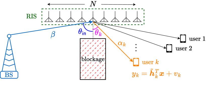
Consider a RIS-assisted downlink scenario using a BS with only one active antenna, where the BS only provides the required power and the phases on RIS are used to modulate information. The problem settings of concern are illustrated in Figure 1. Assuming the RIS is a uniform linear array (ULA), the received signal for user can be written as
| (1) |
where
is the arrival steering vector from the BS to the RIS; and
| (2a) | ||||
| (2b) | ||||
is the downlink steering vector of the RIS to the -th user. Observe the resultant end-to-end channel from the BS to the user:
Remark that this is also referred to as a cascaded channel. Here, is the angle of arrival from the BS to the RIS, and is the angle of departure from the RIS to the -th user. The background noise is assumed to follow complex Gaussian distribution with zero mean and variance. We assume the direct link between the BS and the user is unavailable because, e.g. there is a blockage between the source and sink. The constant envelope signal vector
are the RIS’s reflection coefficients to be designed. In practice, the reflection angles should be quantized to a finite number of phases. They are reconfigured with respect to the channel state information and the carried information available at a centralized processing unit that controls both the BS and the RIS. In the current literature, many of the existing works focus on using optimization over , or equivalently, , to achieve a satisfying performance metric, e.g. the sum rate or the minimum rate of the BS and the -th receiver. We assume the centralized processing unit has full knowledge of the CSI by, such as channel estimation through the pilot stage, in the remainder of this paper.
3 Spatial Modulation for RIS
3.1 First-order Modulation
In this section, we briefly review the concept of modulation [19]. Figure 2 shows the system diagram of the first-order modulator. Widely used in temporal ADC/DAC designs, the system reads in a real-valued sequence and generates a binary sequence by
| (3) |
where denotes the quantization distortion introduced at the signum function , which is used to model an one-bit converter. The term denotes the delayed quantization noise, which is fed back to the quantizer’s input. By taking Fourier transform on both sides of (3), the modulator can be described by the system equation
| (4) |
where denotes the discrete time Fourier transform of the sequence . Notice the noise-shaping response is a high-pass filter. This implies the quantization noise is shaped toward the high frequency band. By assuming the input signal is low-pass, it can be separated from the quantization noise by applying a low-pass filter at the one-bit output signal. This technique is called noise-shaping in the literature. We should mention that the modulator may suffer from unbounded quantization noise due to the feedback path of . A sufficient condition to avoid this is to limit the input signal amplitude to , which leads to a bound on [20]. This is called the no-overload condition. Effectively, this guarantees that the quantization noise in the system (3) is stable.

In [17], modulation has been applied in the spatial domain to handle binary MIMO downlink precoding. The key assumption is that the base station is a uniform linear array (ULA), which means the downlink channel follows (2). We summarize some important aspects of the space-time duality when applying a spatial modulator to MIMO downlink:
-
•
the temporal feedback in (3) is treated as passing the quantization noise incurred at each antenna to the adjacent antenna;
-
•
the noise-shaping effects in the spatial frequency domain, i.e. the angle relative to the ULA’s broadside; and
-
•
the low-pass nature of the temporal input signal leads to the requirement on the user’s angle to be small, e.g. within .
Furthermore, the band-pass modulation [21, 19] adjusts the noise-shaping response to null a designated frequency. When applied to spatial modulation, the effect is that the quantization noise will shaped toward a sector region other than near the broadside, e.g., can be a notch filter that has zero response at . This is proposed as an angle-steered modulator [17], as to be described in the next session.
3.2 Angle-Steered Modulator with Phase Quantizer
Consider an angle-steered spatial modulator that generates discrete constant envelope output alphabet with points sampled on the unit circle . The system diagram is shown in Figure 3. The phase-quantization process can be characterized as
| (5) |
the phase-quantizer returns to the nearest phase on the unit circle, i.e. , and is the quantization error introduced by . The end-to-end relation of the modulator is
| (6) |
The effect of the phase-shifting term in the feedback path of lies in tilting the noise-shaping effect from the low-pass region to a region centering at , as can be seen from the system response
following (4). The noise-shaping response is now a notch filter that is null at . To ensure the error sequence magnitude is bounded, we make an assumption on the input sequence using:

Fact 1
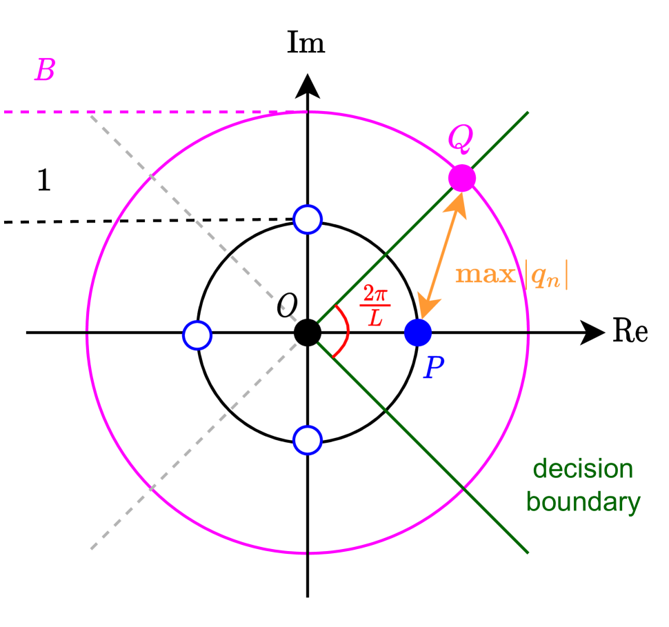
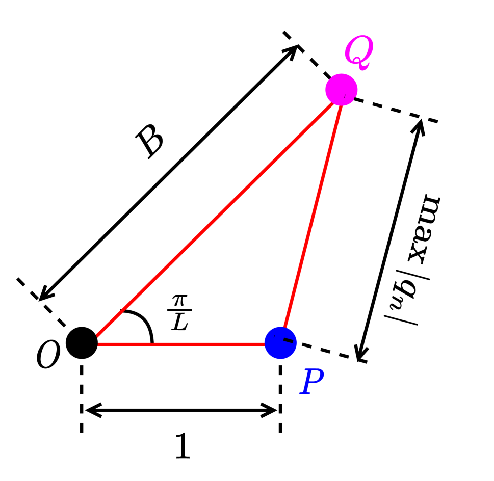
Proof. Let be the quantizer input, and denote such that . Observe the triangle formed by the origin , the phase-quantized point and the point lying on the circumference of the circle originating at and with radius , and intersects the decision boundary of . See a visualization of the complex plane in Figure 4(a). If we fix , we see in Figure 4(b) is an isosceles triangle.111We fix because it is the worst case maximum quantization noise when , which corresponds to the quantizer’s input of . Thus, we can construct the sine law , which can be rewritten as
| (8) |
wherein we have used the identity . The last inequality follows from using the double angle formula for sine function. The proof is completed by observing the no-overload condition .
Corollary 1
Consider the modulator in (5). The maximum modulator amplitude is when , i.e. when the quantizer is continuous-phased.
Proof. It suffices to check, in (8), when . The ratio
wherein we used , which is true when is large.
Remark 1 (Overloading)
We should remark that Fact 1 is a sufficient condition to guarantee . However, it is also true that overloading does not necessarily lead to unbounded quantization noise. In fact, it has been reported that a moderate level of overloading could lead to performance gains in empirical observations, e.g. in [17, 18]. Precisely, it is quite common in the literature to purposefully violate the input sequence amplitude constraint (7) by feeding in a signal that has amplitudes larger than . We resort to empirical studies in order to illustrate the effect overloading may potentially bring.
We now discuss the principle of precoding in the context of interest. Given a free-space precoding vector , which can be generated from traditional precoding scheme such as the zero-forcing precoder, we design the reflective coefficients by spatial modulation. The received signal model yields
wherein we denote as the quantization error vector, and as the delayed quantization error vector. The effective noise component can be evaluated as
and the inner product is
where we let . Using the same derivations in [17, eqn. 11], we assume a large and obtain
where is the variance of , and is the background noise power. This means we can choose such that in order to minimize . The physical meaning of the above derivation is that, if the user angles ’s lie within a small angular sector, then the quantization error term will have little effect on the effective noise power . The following assumption is used in the above derivations:
Assumption 1
The magnitude of the quantization error sequence is uniformly i.i.d. in , and the phase is uniformly distributed on . This allows us to write .
We consider -ZF precoding[17, Subsection 5.1] for the design of in the following. Specifically, the precoding vector reads
whereas , and . Under this setting, the received signals read as
and the symbol detection task at the receiver side can be performed by .
Remark 2 (Subtractive Dithers)
It is worth-noting that Assumption 1 may not hold in general as the quantization error is, ultimately, dependent on the input signal sequence . A widely adopted technique in combating this reality is to introduce some subtractive dithers. Specifically, given an artificially generated random dither signal , where , we modify the input signal by, e.g.
| (9) |
At the receiver side, we can subtract the dither back by re-modifying the decision function as
to counteract the effect of dithering on the detection performance. We can do so because the user devices can obtain the CSI and the scaling term from pilot stage, and can be regenerated at the user’s side by using the same random seed.
4 Numerical Results
This section evaluates the bit error rate (BER) performance of the proposed -ZF, the direct quantized ZF and the unquantized ZF. Precisely, the unquantized ZF makes an ideal assumption on the RIS such that it can absorb different levels of energy and reflect
| (10) |
This implies , which is not a constant envelop signal vector. The quantized ZF means the RIS reflects only the angle of the ZF precoder, i.e. , which satisfies the constant envelop nature for the RIS reflective coefficients.
The simulation settings are as follows. The number of antenna element at the RIS is , and the number of target remote users is . The inter-antenna spacing of the RIS is . The angle of arrival from the BS to the RIS is . The complex channel gain has a phase uniformly drawn from , and the amplitude is generated by , where and is uniformly drawn from . The angle of departure from the RIS to users are randomly picked from , and they are separated by at least . The complex channel gains from the RIS to users ’s are generated in the same fashion of that for . The results are obtained by Monte-Carlo trials of block-fading channels, with the block length . We assume a symbol constellation of -ary QAM in our simulations.
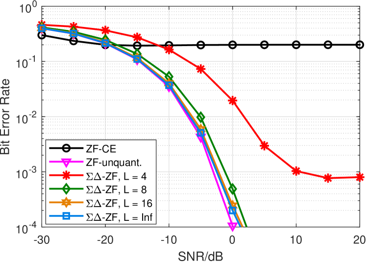
Figure 5 shows the BER performance for the proposed -ZF method with different number of discrete phases . The benchmark scheme “CE-ZF” means the ZF scheme (10) is constant-envelop quantized with continuous phase, i.e. . The result indicates that the proposed -ZF scheme may achieve the performance of unquantized ZF with a higher number of discrete phases . Also, it is noticed that the performance gain between and is substantial, but the gain of increasing from to is smaller. The performance of is comparable to the continuous phase counterpart.
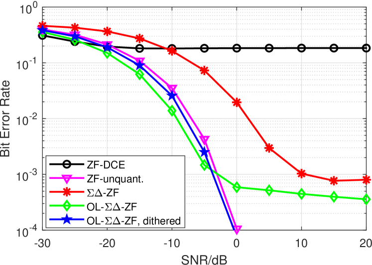
In the previous experiment, we found that the -ZF scheme with discrete phases admits a huge performance gap with the unquantized ZF counterpart, as it suffers from heavy error flooring effects. We try to narrow that gap by using the heuristics of overloading and subtractive dithers. Figure 6 presents the simulation results. The legend “ZF-DCE” means the -phases quantized signal of the unquantized ZF (10), i.e. . Here, we first overload the modulator by intentionally increasing the input signal amplitude to , which violates (7) in Fact 1. The performance is captured by the legend of “OL--ZF”. We see an improvement in the low SNR region, but the effect error flooring remains severe. Next, we apply subtractive dithers (9) to the overloaded modulator. The result is captured by the legend “OL--ZF, dithered”. It is empirically found that the proposed scheme with achieves a comparable BER performance with the unquantized ZF, under the assistance of the tricks in the aforementioned remarks.
5 Conclusions
This paper investigates the practical design of using phases on RIS for transmitting information. It provides an optimization-free solution based on applying modulation to RIS reflective coefficient designs, which is known to be hard due to the constant modulus constraints or discrete phase constraints. The proposed approach is computationally friendly and showcases competitive BER performance in numerical simulations. More practical settings, such as when the RIS is a rectangular planar array, and when there exist direct links between the BS and the users, are left for future studies.
References
- [1] Shi-Wei Qu, Huan Yi, Bao Jie Chen, Kung Bo Ng, and Chi Hou Chan, “Terahertz reflecting and transmitting metasurfaces,” Proc. IEEE, vol. 105, no. 6, pp. 1166–1184, Jun. 2017.
- [2] E. Basar, M. Di Renzo, J. De Rosny, M. Debbah, M. Alouini, and R. Zhang, “Wireless communications through reconfigurable intelligent surfaces,” IEEE Access, vol. 7, pp. 116753–116773, Aug. 2019.
- [3] Ying-Chang Liang, Ruizhe Long, Qianqian Zhang, Jie Chen, Hei Victor Cheng, and Huayan Guo, “Large intelligent surface/antennas (LISA): Making reflective radios smart,” J. Commun. Inf. Netw., vol. 4, no. 2, Jun. 2019.
- [4] Chongwen Huang, Alessio Zappone, George C Alexandropoulos, Mérouane Debbah, and Chau Yuen, “Reconfigurable intelligent surfaces for energy efficiency in wireless communication,” IEEE Trans. Wireless Commun., vol. 18, no. 8, pp. 4157–4170, Aug. 2019.
- [5] Q. Wu and R. Zhang, “Towards smart and reconfigurable environment: Intelligent reflecting surface aided wireless network,” IEEE Commun. Mag., vol. 58, no. 1, pp. 106–112, Jan. 2020.
- [6] Tao Jiang, Hei Victor Cheng, and Wei Yu, “Learning to reflect and to beamform for intelligent reflecting surface with implicit channel estimation,” IEEE J. Sel. Areas Commun., vol. 39, no. 7, pp. 1931–1945, Jul. 2021.
- [7] Tao Jiang and Wei Yu, “Interference nulling using reconfigurable intelligent surface,” IEEE J. Sel. Areas Commun., vol. 40, no. 5, pp. 1392–1406, May 2022.
- [8] Emil Björnson, Özgecan Özdogan, and Erik G. Larsson, “Intelligent reflecting surface versus decode-and-forward: How large surfaces are needed to beat relaying?,” IEEE Wireless Commun. Lett., vol. 9, no. 2, pp. 244–248, Feb. 2020.
- [9] Hei Victor Cheng and Wei Yu, “Multiplexing gain of modulating phases through reconfigurable intelligent surface,” in IEEE Int. Symp. Inf. Theory (ISIT), July 2021, pp. 2346–2351.
- [10] Hei Victor Cheng and Wei Yu, “Degree-of-Freedom of modulating information in the phases of reconfigurable intelligent surface,” IEEE Tran. Inf. Theory, Accepted. [Online] Available: https://arxiv.org/abs/2110.01441.
- [11] Amir K. Khandani, “Media-based modulation: A new approach to wireless transmission,” in IEEE Int. Symp. Inf. Theory (ISIT), Jul. 2013, pp. 3050–3054.
- [12] Roy Karasik, Osvaldo Simeone, Marco Di Renzo, and Shlomo Shamai Shitz, “Adaptive coding and channel shaping through reconfigurable intelligent surfaces: An information-theoretic analysis,” IEEE Trans. Commun,, vol. 69, no. 11, pp. 7320–7334, Nov. 2021.
- [13] W. Yan, X. Yuan, Z. Q. He, and X. Kuai, “Passive beamforming and information transfer design for reconfigurable intelligent surfaces aided multiuser MIMO systems,” IEEE J. Sel. Areas Commun., vol. 38, no. 8, pp. 1793–1808, Aug. 2020.
- [14] S. Guo, S. Lv, H. Zhang, J. Ye, and P. Zhang, “Reflecting modulation,” IEEE J. Sel. Areas Commun., vol. 38, no. 11, pp. 2548–2561, Nov. 2020.
- [15] Hei Victor Cheng and Wei Yu, “Modulating data using reconfigurable intelligent surface by symbol level precoding,” in Int. Symp. Wireless Commun. Sys. (ISWCS), 2022, pp. 1–6.
- [16] Shilpa Rao, A. Lee Swindlehurst, and Hessam Pirzadeh, “Massive MIMO channel estimation with 1-bit spatial Sigma-Delta ADCS,” in Proc. IEEE ICASSP, 2019, pp. 4484–4488.
- [17] Mingjie Shao, Wing-Kin Ma, Qiang Li, and A. Lee Swindlehurst, “One-bit sigma-delta mimo precoding,” IEEE J. Sel. Top. Signal Process., vol. 13, no. 5, pp. 1046–1061, 2019.
- [18] Mingjie Shao, Wing-Kin Ma, and Lee Swindlehurst, “Multiuser massive mimo downlink precoding using second-order spatial sigma-delta modulation,” in IEEE Int. Conf. Acous. Speech Signal Process. (ICASSP), 2020, pp. 8966–8970.
- [19] P.M. Aziz, H.V. Sorensen, and J. vn der Spiegel, “An overview of Sigma-Delta converters,” IEEE Signal Process. Mag., vol. 13, no. 1, pp. 61–84, 1996.
- [20] R.M. Gray, “Quantization noise spectra,” IEEE Trans. Inf. Theory, vol. 36, no. 6, pp. 1220–1244, 1990.
- [21] Richard Schreier and Martin Snelgrove, “Bandpass Sigma-Delta modulation,” Electron. Lett., vol. 25, pp. 1560–1561, 1989.