Arxiv \toggletrueArxiv
Closed Loop Molecular Communication Testbed: Setup, Interference Analysis, and Experimental Results
Abstract
In this paper, we present a fluid-based experimental molecular communication (MC) testbed that, similar to the human cardiovascular system, operates in a closed circuit tube system. The proposed system is designed to be biocompatible, resource-efficient, and controllable from outside the tube. As signaling molecule, the testbed employs the green fluorescent protein variant "Dreiklang" (GFPD). GFPDs can be reversibly switched via light of different wavelengths between a bright fluorescent state and a less fluorescent state. Hence, this property allows for writing and erasing information encoded in the state of the GFPDs already present in the fluid via radiation from outside the tube. The concept of modulating the GFPDs existing in the channel at the transmitter for information transmission, instead of releasing new molecules, is a form of media modulation. In our testbed, due to the closed loop setup and the long experiment durations of up to 250 min, we observe new forms of inter-symbol interferences (ISI), which do not occur in short experiments and open loop systems. In particular, up to four different forms of ISI, namely channel ISI, inter-loop ISI, offset ISI, and permanent ISI, occur in the considered system. To mitigate inter-loop ISI and offset ISI, we propose a light based eraser unit. We experimentally demonstrate reliable information transmission in our testbed achieving error-free transmission of 500 bit at a data rate of 6 based on a sub-optimal low-complexity detection scheme.
I Introduction
Synthetic molecular communication (MC) refers to information transmission based on signaling molecules [1]. This paradigm makes it possible to design systems capable of operating in environments unsuitable for electromagnetic wave-based communication, such as the human cardiovascular system. For the latter, the Internet of Bio-Nano-Things (IoBNT) has been proposed, a communication network potentially integrating many in-body nanodevices that utilize MC to exchange information [2].
So far, such systems exist only in theory, i.e., eHealth products and applications based on MC are not available, yet. To drive research towards first applications, several MC testbeds have been developed in recent years (see [3, 4] for a comprehensive overview of existing testbeds). For example, the authors in [5] propose a fluid-based multiple-input multiple-output (MIMO) system as a prototype for the IoBNT.
However, the prototype in [5] and all other fluid-based MC testbeds operating in tubes, except that in [6], are open loop. Open loop refers to systems where the background fluid used in the experiment can enter or leave the system during operation. As a result, in these testbeds, the signaling molecules are added to the tube system at one point, e.g., via an injection, used once to transmit information, and then are collected as waste together with the flowing out background fluid at the end of the tube. There are two major drawbacks to such systems: First, long-term transmission experiments generate a lot of waste. Second, many of the intended applications occur in a closed loop environment, e.g., the human cardiovascular system, and cannot be accurately simulated in open loop testbeds.
Therefore, experimental MC system are required that can operate in closed loop. Currently, there is only one MC testbed that features a closed loop [6]. In [6], a fluid is pumped in a loop system while fluorescent particles are injected, detected, and then diluted. Hence, the applicability of the testbed in [6] for long experiment durations is limited because the signaling molecules can be used only once, which is not resource efficient.
In this context, we propose the first experimental closed loop MC system in which reversibly switchable signaling molecules are reused multiple times, enabled by molecular media modulation [7, 8]. In media modulation, the state of signaling molecules already present in the medium is changed to transmit information, i.e., no additional molecules are injected or removed from the system during operation. As signaling molecule, we adopt the biocompatible green fluorescent protein variant "Dreiklang" (GFPD) [9, 10]. GFPD molecules can be reversibly switched between a bright fluorescent ON state and a less fluorescent OFF state via light stimuli of different wavelengths [10]. This allows for writing and erasing information employing an optical transmitter (TX) and eraser (EX) in our testbed, respectively. The state of the GFPDs, i.e., the transmitted information, is read out via fluorescence detection at the receiver (RX).
The main contributions of this paper are as follows:
-
•
We utilize light-based media modulation to transmit information in a closed loop tube system using the states of GFPD molecules. This form of media modulation enables to operate TX, EX, and RX outside of the tube. As a result, they do not interfere with the propagation of the signaling molecules inside the tube; a feature that is beneficial, e.g., for healthcare applications.
-
•
Because of the closed loop and long experiment durations, the system is affected by new forms of inter-symbol interference (ISI). These forms of ISI become apparent on different time scales and are characterized in this work. Furthermore, we discuss and experimentally implement suitable ISI mitigation methods. Moreover, we implement two different detection schemes and test their robustness to ISI.
-
•
We experimentally prove that error-free information transmission of at and at is feasible in a closed loop tube system. The corresponding experiments take and , respectively, during which of GFPD solution is continuously reused.
A preliminary and simplified version of the testbed was briefly presented as part of [8]. In [8], the experiment duration was only , which did not allow to i) evaluate the resource efficiency of the testbed, ii) characterize the ISI, and iii) experimentally determine the symbol error rate (SER) for different detection schemes, which are new contributions of this work.
The remainder of this paper is organized as follows. In Sections II and III, we describe GFPD and the experimental MC setup, respectively. In Section IV, we characterize the testbed and the different forms of ISI. The employed detection methods are introduced in Section V, and in Section VI, we evaluate the end-to-end communication performance. Finally, Section VII concludes the paper and outlines topics for future work.
II Signaling Molecule: GFPD and its Properties
GFPD is a photoswitchable and biocompatible green fluorescent protein (GFP) introduced in [10]. In the following, we discuss these two properties which are key for the proposed MC system.
II-A Photoswitchability
In general, photoswitchability means that the properties of a molecule can be changed upon exposure to light of specific wavelengths. In the case of GFPD, photoswitchability allows for a reversible switching of its fluorescence between two111In fact, a third state exists, which we denote as equilibrium state. In the absence of light, GFPD may switch to this state, which shows a similar fluorescence as the ON state. As the equilibrium state’s fluorescence is only slightly higher, in this work, for simplicity of presentation, we do not differentiate between the ON state and the equilibrium state. distinct states, namely the ON and OFF states, which can be controlled by irradiation of light with different wavelengths. In particular, GFPD may be switched to the ON and OFF states upon irradiation with light of wavelengths and , respectively. The success of the switching depends on the intensity of the irradiation. Furthermore, GFPD can also spontaneously switch back to the ON state due to thermal relaxation. The thermal relaxation of GFPD to the ON state has a half-life of at room temperature [10]. Only GFPDs in the ON state show a high fluorescence, i.e., emit light at a wavelength of after being excited by light of wavelength . After multiple photoswitching cycles, photobleaching of GFPD may occur [10]. Here, photobleaching refers to the chemical modification of the GFPD upon exposure to light of high energy. The effect of photobleaching is a gradual diminishing of the fluorescence intensity upon repeated irradiation which can be interpreted as GFPD degradation. The authors in [10] show that, for GFPD, the switching efficiency, robustness towards photobleaching, and fluorescence intensity are high, which makes GFPD well suited for the use in our testbed.
II-B Biocompatibility
III Testbed Setup
In this section, we introduce the testbed. Fig. LABEL:fig:GFPD_Testbed shows the entire testbed (top panel) as well as a schematic representation of its working principle (bottom panel). We highlight the different building blocks of the testbed by colored boxes in Fig. LABEL:fig:GFPD_Testbed.
IV Communication Link Characterization
In this section, we mathematically model the received signal and characterize the different forms of ISI present in the testbed.
IV-A Mathematical Description of the Received Signal and the Pilot Sequence
In the investigated experimental MC system, binary symbols , , are transmitted and signal is received. can be partitioned as follows
| (1) |
where signal corresponds to symbol . For detection, we use samples , i.e., we use one sample per symbol interval , which corresponds to the sampling instant , where the local minimum for a bit 1 transmission is expected. The value of is experimentally determined based on a pilot sequence of length given by , , which is sent at the beginning of each transmission and is known at the RX. In particular, to obtain , we take the median of the indices of the local minima of all bit 1 transmissions in . For the experiments shown in this work, we use the pilot sequence , of length , which is identical to the bit sequence used in Fig. LABEL:fig:transmission_20s.
IV-B Channel Symbol Responses
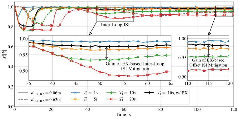
Fig. 1 shows the received signals for different TX and channel settings for a single bit 1 transmission. In particular, we vary the TX irradiation duration and . Increasing also increases the fluorescence intensity drop until for and exhibits a minimum for and , respectively. Increasing further does not change the minimum fluorescence intensity as the average energy that a GFPD molecule receives is limited. In particular, the average energy received by a GFPD is dependent on the irradiation power of the light emitting diodes at the TX, the average flow velocity , the length of the TX , and . A detailed investigation of this aspect is left for future work.
Moreover, we see in Fig. 1 that increasing from to results in a less severe fluorescence intensity drop, as the modulated GFPDs have more time to spontaneously switch back to the ON state and disperse further during the propagation from TX to RX.
Finally, Fig. 1 shows also one result for the case with EX. Here, the EX is started a few minutes before . We observe that, with the EX, the drop in is smaller compared to the case without the EX. This can be explained by the slightly smaller difference between ON state and OFF state compared to the difference between equilibrium state and OFF state, cf. Footnote 1. The different forms of ISI are discussed in the next section.
IV-C ISI Characterization and Mitigation
We identified four different forms of ISI in our testbed, with three of them appearing only for long term experiments in closed loop systems. These forms of ISI occur on different time scales and are discussed in the following.
IV-C1 Channel ISI
During their propagation within the channel from TX to RX, signaling molecules from consecutive symbols may overlap, leading to ISI. To differentiate between different forms of ISI, we refer to this form as channel ISI. Channel ISI has been observed in existing MC testbeds, e.g., [12, 13]. We refer to [13] for a comprehensive discussion of channel ISI.
Channel ISI can be mitigated by using a guard interval, during which the TX is inactive and the signaling molecules have time to be transported out of the channel before the next symbol is transmitted. Of course, the success of the ISI mitigation depends on the guard interval duration , and improves for increasing . However, increasing decreases the data rate, i.e., there exists a tradeoff between the performance of channel ISI mitigation and the data rate. Note that also without a guard interval, the impact of channel ISI (and not channel ISI itself) on the sample may vary dependent on the symbol duration and .
IV-C2 Inter-Loop ISI
Due to the closed loop, a second form of ISI occurs, which we call inter-loop ISI. As the signaling molecules remain in the system, they may interfere not only with neighbouring symbols but also with symbols transmitted much later. In particular, GFPD molecules, which are switched to the OFF state during a bit 1 transmission, may travel several times through the loop before they spontaneously switch back to the ON state. Hereby, these signaling molecules likely impact the received signal multiple times, while the distinctness and the number of recurrences depend on the length of the loop and the half-life of the OFF state . The left inset of Fig. 1 shows that inter-loop ISI is visible as a dip in the received signal and can be reduced by utilizing an EX. Note that the first inter-loop ISI peak appears approximately after the main peak, which is close to the calculated loop duration of . Furthermore, Fig. 1 shows that inter-loop ISI becomes increasingly severe as increases.
IV-C3 Offset ISI
Since the OFF state GFPDs disperse within the system over the loops, the ISI gradually transforms from inter-loop ISI, characterized by distinctive dips, to a temporal offset of the fluorescence intensity, which we denote as offset ISI. The offset ISI is visible in Fig. 1 as an overall lower fluorescence intensity level compared to the initial level. In particular, for strong offset ISI, the received fluorescence intensity in response to a bit 0 transmission is reduced, and therefore closer to the intensity in response to a bit 1 transmission. This affects the reception performance. The intensity of offset ISI depends on the number of bit 1 transmissions, symbol duration , and half-life , and can be mitigated by using an EX. The right inset of Fig. 1 shows that offset ISI, visible as the difference between and the initial fluorescence intensity, increases for increasing and decreases when utilizing the EX.
IV-C4 Photobleaching and Permanent ISI
Finally, after intensive irradiation, GFPD molecules may be permanently degraded. This effect occurs in long experiments and is referred to as photobleaching. While the decrease in fluorescence intensity due to offset ISI is reversible, photobleaching results in a long term and permanent decrease of GFPD fluorescence. As GFPDs are irradiated by the EX, the RX, and the TX in the testbed, all three light sources contribute to photobleaching. Therefore, we denote the portions caused by the TX, by the EX, and by the RX as permanent ISI, eraser bleaching, and measurement bleaching, respectively, where only the permanent ISI is dependent on the transmitted signal222Note that only the TX irradiation varies as a function of the transmitted sequence. Therefore, only the photobleaching caused by the TX can be interpreted as ISI, whereas the photobleaching caused by the EX and the RX is independent of the transmitted sequence.. Photobleaching affects the availability of GFPD for media modulation and hereby impacts the transmission of future symbols. Photobleaching increases with the irradiation energy, e.g., for higher irradiation power and longer irradiation duration [10, Suppl. Fig. 7]. Therefore, there exists a tradeoff between switching accuracy (which increases with the irradiation energy provided by the EX and TX) and photobleaching. We observe that photobleaching limits the maximum duration of our experiments. As it manifests itself only after many transmission cycles, it is not visible in Fig. 1.
IV-C5 ISI Mitigation
To overcome inter-loop and offset ISI, we exploit the spontaneous switching property of GFPD and the EX for passive and active inter-loop and offset ISI mitigation, respectively. In fact, GFPDs spontaneously switch back from the OFF state to the ON state with a half-life of . Hereby, information modulated to the state of the GFPDs is erased naturally, and offset ISI is reduced. In addition, the EX actively triggers the switching to the ON state. If the EX is ideal, it switches all traversing GFPDs from the less fluorescent OFF state to the fluorescent ON state. Of course, in reality, only a fraction of the GFPDs may be switched because the power of the LEDs is limited. Fig. 1 reveals the success of EX-based ISI mitigation for . In particular, we see that both inter-loop ISI and offset ISI are reduced, which increases the overall fluorescence intensity by approximately 4%333Note that the forms of ISI mitigation described here impact the signaling molecules themselves. Hence, unlike equalization schemes, they are not part of the detection scheme at the RX and therefore do not contribute to the computational complexity needed for detection..
V Detection Methods
In the following, we describe two different threshold detection schemes. In all cases, the pilot sequence is used to determine the optimal threshold value. However, the detection techniques differ in terms of complexity. The basic threshold detection (BD), presented in Section V-A, uses symbol-by-symbol detection, i.e., each symbol is detected independent of the other symbols. In contrast, the differential threshold detection (DD) introduced in Section V-B exploits two consecutive samples.
V-A Basic Threshold Detector
For the BD, the threshold is used to estimate the transmitted symbol as follows
| (2) |
To find a suitable threshold, we choose the threshold value that minimizes the Hamming distance between the symbols of pilot sequence and their estimates. If the choice of is ambiguous, i.e., more than one minimizes the Hamming distance, we select the lowest of the possible values. Once is computed from the pilot sequence, the symbols for are computed based on (2).
V-B Differential Threshold Detector
Another threshold based approach is the DD scheme. DD was proposed for MC in [14] and implemented for an MC testbed in [12]. In fact, in [12], the authors have shown the robustness of DD against a slow drift in the received signal, which motivates the usage of such a detector also in this work.
For DD, the difference between the current sample and the sample of the previous symbol is utilized. is defined as follows
| (3) |
If the preceding and the current symbol are equal, the difference between the sampling values, i.e., is likely to be small in its absolute value. If a change in transmitted symbols occurs, then will more likely have a large absolute value. In this case, if a bit 0 is transmitted after a bit 1, we expect and if a bit 1 follows a bit 0, . These considerations are exploited in the decision rule of DD as follows
| (4) |
To find a suitable value for , we first determine the set of indices of the transmitted pilot symbols that are repetitions of their respective preceding symbols as follows
| (5) |
Then, we use this set to find the threshold as follows
| (6) |
i.e., based on our observation that decreases with increasing experiment duration, we use the maximum here.
VI End-To-End Communication Performance
In this section, we discuss the end-to-end communication performance of the developed testbed. In particular, we evaluate the SER for different transmission lengths and different data rates using the detection schemes discussed in Section V. We show results with and without EX-based ISI mitigation.
VI-A Visualizing the Detection Schemes
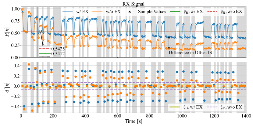
The top panel of Fig. 2 shows the normalized fluorescence intensity (solid orange and blue lines) over time and the sampled values (markers) using as setting and . In addition, the bottom of Fig. 2 shows the corresponding difference of two consecutive samples (dots). We further show the threshold values and , which are derived based on the pilot sequence, whose end is highlighted by a black vertical solid line.
The top panel of Fig. 2 shows that, even without a guard interval, clear peaks are visible in the received signal for bit 1 transmissions. We observe that the amplitudes of the recorded signals decrease over time, which is expected. In fact, without the EX, the overall fluorescence intensity level decreases fast, which is due to the increasing offset ISI, cf. Section IV-C. In contrast, when using the EX, the decrease is slower, but still exists. We conclude that in this case the decrease is mainly caused by degradation of GFPD due to photobleaching, cf. Section II. Moreover, we observe from the bottom panel that the dots, which denote , approach over time. This indicates that the difference of the fluorescence intensity levels of bits 0 and bits 1 decreases over time, posing a challenge especially for long term experiments.
Fig. 2 further shows that is practically identical for the cases with and without EX and is, in this case, determined by the second sample within the pilot sequence of length . In fact, the second sample appears at a time instant where has not yet been impacted by the EX, which explains the similarity. Moreover, we observe that used for the case without EX is larger compared to that for the case with EX. This is intuitive as for the EX-free case varies more, which is reflected in the larger .
VI-B SER Evaluation
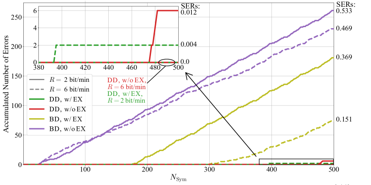
Fig. 3 shows the accumulated number of transmission errors as a function of the transmission sequence length for different settings. Hence, in this plot, horizontal lines indicate error free transmission for the length of the line. Additionally, we show the SER for , which is the maximum number of symbols transmitted, on the right-hand-side -axis.
First, we discuss the results for . From Fig. 3, we observe that the BD scheme enables error-free MC only at the beginning of the experiment. For long transmission times, the BD scheme yields a poorer performance compared to the DD scheme. In fact, due to offset ISI and photobleaching, the channel state information gained from the pilot sequence and used for the computation of is eventually outdated, which leads to an increase in errors. This can also be observed in the top panel of Fig. 2, where for the orange curve is always below . We observe that, when using the EX to mitigate offset ISI, the first errors occur later. We further observe that DD, due to its robustness to imperfect channel state information, fails only for two symbols and not at all for the cases with and without EX, respectively. In particular, offset ISI and photobleaching effects are successfully canceled out when taking the difference between two consecutive samples. We conclude that, when using DD444Note that the slightly higher RX complexity of the DD compared to the BD is negligible., there exist system settings, where an EX is not essential.
Finally, we observe that decreasing the data rate from to by using a guard interval of duration increases the error rate, which seems counter intuitive at first. In fact, using is expected to decrease the impact of channel ISI, while leaving the other forms of ISI unmodified. However, as for the experiment takes three times longer, eraser bleaching and measurement bleaching becomes more severe, which explains the performance loss.
VII Conclusion
In this work, we introduced an experimental closed loop tube-based testbed, which can be used for MC with GFPD as signaling molecule. We showed that media modulation can be utilized to transmit binary data in a closed loop system over a long transmission time duration. We identified and characterized inter-loop ISI, offset ISI, and permanent ISI as specific forms of ISI, which occur for long experiments in closed loop testbeds and appear on different time scales. Finally, we proved that our testbed enables error-free signal transmission of at a data rate of when using DD.
While, in this work, we identified new forms of ISI and proposed methods to mitigate them, it would be helpful to understand how to handle possible resulting tradeoffs. For example, analyzing the tradeoff between EX-based ISI mitigation and eraser bleaching, which limits the operation duration of the testbed, is an interesting topic left for future work. Investigating the possibility of increasing the data rate by using higher-order modulation via different irradiation intensities is another promising direction for further research.
References
- [1] T. Nakano, A. W. Eckford, and T. Haraguchi, Molecular communication. Cambridge, U.K.: Cambridge Univ. Press, Sep. 2013.
- [2] I. F. Akyildiz, M. Pierobon, S. Balasubramaniam, and Y. Koucheryavy, “The Internet of Bio-Nano Things,” IEEE Commun. Mag., vol. 53, no. 3, pp. 32–40, 2015.
- [3] S. Lotter et al., “Experimental research in synthetic molecular communications – Part I,” IEEE Nanotechnol. Mag., vol. 17, no. 3, pp. 42–53, Jun. 2023.
- [4] ——, “Experimental research in synthetic molecular communications – Part II,” IEEE Nanotechnol. Mag., vol. 17, no. 3, pp. 54–65, Jun. 2023.
- [5] C. Lee, B.-H. Koo, C.-B. Chae, and R. Schober, “The Internet of Bio-Nano Things in blood vessels: System design and prototypes,” J. Commun. Netw., Apr. 2023.
- [6] N. Tuccitto, G. Li-Destri, G. M. Messina, and G. Marletta, “Fluorescent quantum dots make feasible long-range transmission of molecular bits,” J. Phys. Chem. Lett., vol. 8, no. 16, pp. 3861–3866, Aug. 2017.
- [7] L. Brand et al., “Media modulation based molecular communication,” IEEE Trans. Commun., vol. 70, no. 11, pp. 7207–7223, Sep. 2022.
- [8] ——, “Switchable signaling molecules for media modulation: Fundamentals, applications, and research directions,” IEEE Commun. Mag., pp. 1–7, 2023, Early Access.
- [9] H. A. Richards, C.-T. Han, R. G. Hopkins, M. L. Failla, W. W. Ward, and C. N. Stewart Jr, “Safety assessment of recombinant green fluorescent protein orally administered to weaned rats,” J. Nutr., vol. 133, no. 6, pp. 1909–1912, Feb. 2003.
- [10] T. Brakemann et al., “A reversibly photoswitchable GFP-like protein with fluorescence excitation decoupled from switching,” Nat. Biotechnol., vol. 29, no. 10, pp. 942–947, Sep. 2011.
- [11] J. E. Hall and M. E. Hall, Guyton and Hall Textbook of Medical Physiology e-Book. Philadelphia, PA, USA: Elsevier Health Sciences, 2020, vol. 12th ed.
- [12] L. Grebenstein et al., “Biological optical-to-chemical signal conversion interface: A small-scale modulator for molecular communications,” in Proc. 5th Int. Conf. Nanosc. Comp. Commun. (NANOCOM), 2018, pp. 1–6.
- [13] J. Wang, D. Hu, C. Shetty, and H. Hassanieh, “Understanding and embracing the complexities of the molecular communication channel in liquids,” in Proc. 26th Int. Conf. Mob. Comput. Netw. (MOBICOM), 2020, pp. 1–15.
- [14] B. Li, M. Sun, S. Wang, W. Guo, and C. Zhao, “Low-complexity noncoherent signal detection for nanoscale molecular communications,” IEEE Trans. NanoBioscience, vol. 15, no. 1, pp. 3–10, Dec. 2015.
Acknowledgment
We thank Prof. Stefan Jakobs (Max Planck Institute for Biophysical Chemistry, Göttingen, Germany) for providing a plasmid encoding Dreiklang.