Elastic and inelastic diffraction of fast neon atoms on a LiF surface
Abstract
Grazing incidence fast atom diffraction has mainly been investigated with helium atoms, considered as the best possible choice for surface analysis. This article presents experimental diffraction profiles recorded with neon projectile, between 300 eV and 4 keV kinetic energy with incidence angles between 0.3∘ and 1.5∘ along three different directions of a LiF(001) crystal surface. These correspond to perpendicular energy ranging from a few meV up to almost 1 eV. A careful analysis of the scattering profile allows us to extract the diffracted intensities even when inelastic effects become so large that most quantum signatures have disappeared. The relevance of this approach is discussed in terms of surface topology.
pacs:
34.35.+a,68.49.Bc,34.50.Cx,79.20.Rf,79.60.Bm,34.20.CfI introduction
Grazing incidence fast atom diffraction (GIFAD) employs the same geometry as reflection high energy electron diffraction (RHEED) and has proven to be a robust technique to track online and in-situ thin films growth on surfaces, in particular inside a molecular beam epitaxy vessel [1, 2, 3]. Diffraction with neutral atoms originates exclusively from the top most layer [4, 5]. It is insensitive to electromagnetic fields, and the absence of the charging effect is well suited for fragile organic layers [6, 7].
Elastic diffraction results from the quantum scattering of the projectile on the potential energy landscape (PEL) above the surface. This latter is then accessible by comparison with theory. For applications, helium is the simplest projectile, behaving as a compact, hardly deformable sphere, so that the projectile is essentially repelled by the surface electronic density making the interpretation both easier and more valuable in terms of surface engineering (see Ref. [8, 9] for reviews). With the second-highest binding energy in the periodic table, neon atoms should behave similarly, differing only by a larger number of valence electrons and a larger mass, increasing the momentum transfer to each surface atom and therefore the inelastic effects. Scattering of neon atoms on a LiF(100) surface has already been published, showing inelastic [10] and elastic diffraction profiles [11] along the [110] direction together with theoretical analysis. The present paper reports a full set of diffraction profiles recorded along the [110], [100] and random ([Rnd]) directions with the account of both elastic and inelastic contributions.
Section II presents the experimental arrangement, geometric definitions, and the general strategy for data analysis. Sections III, IV and V present the diffraction profiles recorded on the Laue circle for neon atoms on the LiF surface oriented along the [110], [Rnd] and [100] directions, respectively. Section VI discusses the various strategies used to extract diffracted intensities of each diffraction order from elastic and inelastic data and their relevance to the PEL.
II Setup and data analysis
The typical arrangement of a GIFAD experiment is detailed in Ref. [14], and only a brief description is given here. An ion beam in the keV energy range is neutralized by charge exchange and severely collimated before entering a UHV setup where it interacts at grazing incidence with a crystalline surface. The atoms are collected on a position-sensitive detector located 1 m downstream.
| Symbol | Formula |
|---|---|
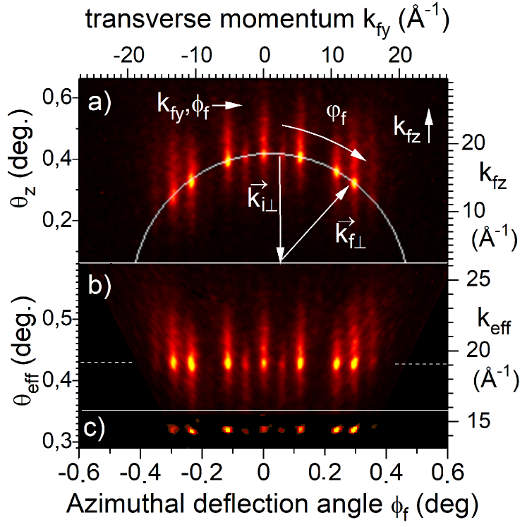
In GIFAD, and for well-aligned conditions, the axial surface channeling approximation (ASCA) holds [15]. In this approximation, the motion along the crystal axis, taken as , is decoupled from the one in the perpendicular () plane. Labeling the initial and final condition with the subscript and respectively, the momentum conservation writes with , the reciprocal lattice vectors associated with the surface periodicity and along and . Giving an infinite mass to the crystal, the energy conservation writes . In well-aligned GIFAD condition, only the Laue circle is observed, the one corresponding to and corresponding to ASCA, i.e. . It is clearly visible in the raw diffraction pattern shown in Fig. 1a). After a polar transform [13] bringing the elastic spots on a straight line, the Bragg structure with is illustrated in Fig. 1b) and Fig. 2. Reversely, we assume here that the intensity of the sharp peaks sitting on the Laue circle corresponds to the elastic diffraction. This is not fully demonstrated as the final momentum is not measured [16] but, even under a vacuum of a few 10-10 mbar, we observe a drastic reduction of the intensity of these peaks within days, probably due to a progressive reduction of the surface coherence length defined as the mean distance between ad-atoms or defects.
In principle, only the elastic diffraction intensity can be linked directly to the shape of the potential energy landscape. This later describes the perfectly periodic lattice, which corresponds to surface atoms at their equilibrium position. Two methods have been proposed to isolate the elastic contribution on the Laue circle. One assumes that the variation of the inelastic intensity is much slower than the angular resolution of the primary beam so that the application of a doubly differential filter isolates the elastic component. The filter is a sum of two Gaussians, one positive having a width and the other one negative having a width .
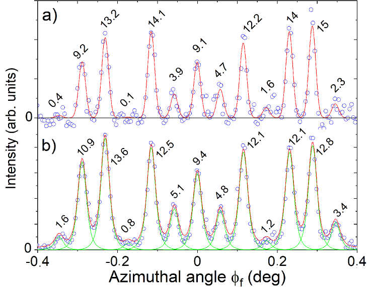
An example of a diffraction pattern using such a filter along the z direction is shown in Fig. 1c). The 1D profiles with or without application of this filter are reported in Fig. 2b) and Fig. 2a) respectively.
The diffraction pattern in Fig. 2b) shows quasi-gaussian peaks along the azimuthal direction , comforting the initial assumption that elastic peaks shape should be close to that of the primary beam. The method is parameter-free, but requires high quality images to limit the noise of the differentiation filter.
Without filter, the raw intensity in Fig. 2a) shows slightly broader peaks with significant wings at their base due to the inelastic component, which may prevent proper measurement of the elastic intensity. We then rely on an important result established with helium. It was shown that when elastic diffraction is significant, then the inelastic and elastic relative intensities are identical [17]. The challenge is then to find an adequate line-shape describing the combination of elastic and inelastic intensities on the Laue circle.
Our first attempt used an empirical description inspired from numerical simulations [17] and made of a product of a Gaussian by a Lorentzian having only one width parameter ( in Table 1). This strategy was used along the [110] direction and is described in section III. Recently, a more general form of the profile [18] was proposed taking into account the resolution and presence of an elastic and inelastic components with relative weight ( in Table 1). The parameters and of the profiles are measured along the [Rnd] and presented in section IV and used to fit the data recorded along the [100] direction and described in section V. All of the diffraction profiles presented here have been recorded on the Laue circle.
III [110] direction
Two sets of data were recorded with neon atoms along the LiF[110] direction, a -scan at =500 eV primary energy and an -scan at =0.42∘ [11].
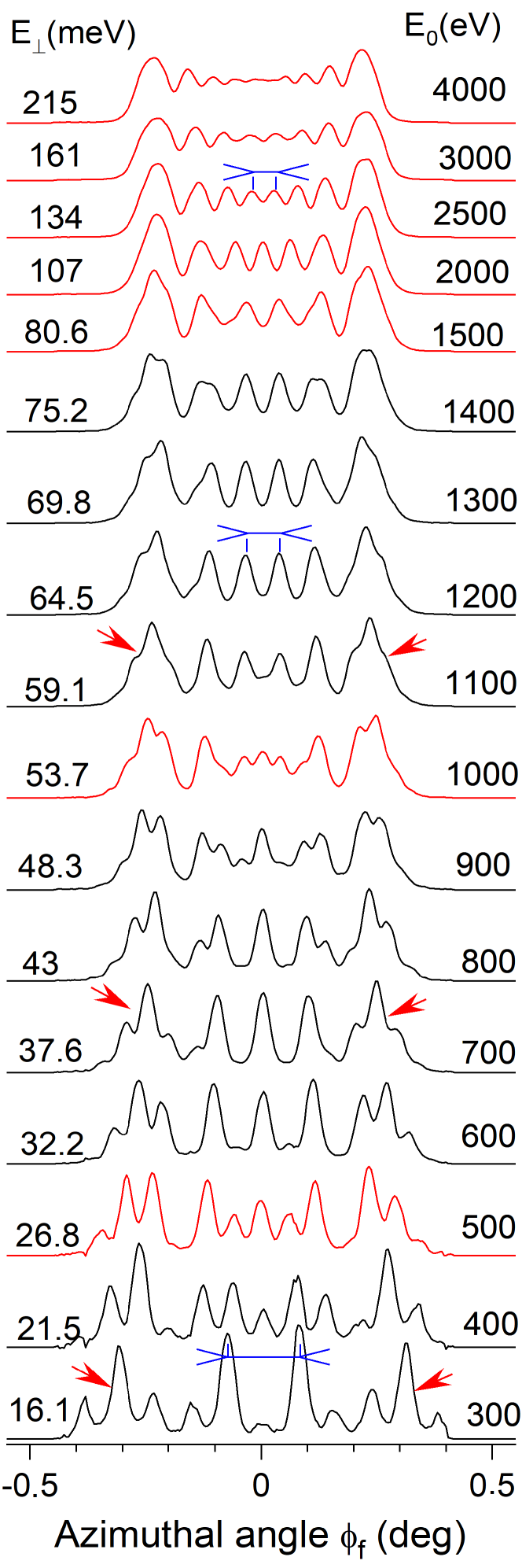
During an -scan the size of the Laue circle is constant, but the Bragg angle indicating the peak separation along scales with so that the number of open channels increases progressively. Twenty-eight snapshots were recorded in less than an hour with a resolution (0.024∘ fwhm). Some raw diffraction profiles are reported in Fig. 3. It shows that line-shape does not increase significantly, but the narrowing of the peak separation leads to a progressive merging of the peaks to a smooth quasi-continuous profile where the distinction between diffraction peaks and supernumerary rainbows [19, 9] is unclear.
This continuous profile gives the impression that the semi-classical link between topology and diffraction profile is preserved, but the progressive weakening of the contrast in the center indicates clearly that the information on the corrugation amplitude is degraded. This is in part balanced by the fact that the natural measurement unit is the wavelength , and this latter reduces at larger values of . It should be noted that this presentation of the scattering profiles is more quantitative than the color plots of the diffraction chart [8, 11], which mainly gives an overall impression of where the maxima are located, leaving weak contributions and line-shapes hardly visible. The diffracted intensities are derived by a fit were all diffraction orders have identical line-shapes as shown in Fig. 4. The diffraction profiles are reasonably well fitted using the same line-shape with a width parameter such that the standard deviation is mdeg, hardly more than the primary beam mdeg. The topmost image where has become half of the linewidth (i.e. less than the fwhm) suggests that unless the exact target alignment is known with an accuracy better that a fraction of the Bragg angle , trying to recover the exact intensity of contributing peaks is a daunting task.
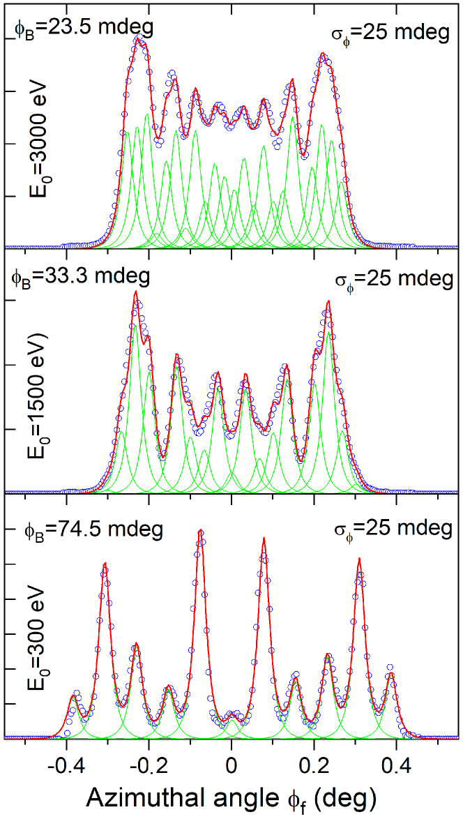
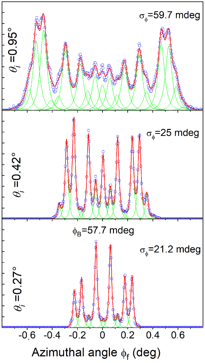
During a -scan the primary beam energy is constant so that the Bragg angle is essentially constant ( within a few ) while the radius of the Laue circle increases allowing also more and more diffraction orders to contribute to the diffraction pattern. The -scan consists in 45 diffraction images recorded between 0.27∘ and 0.94∘ with a resolution of mdeg. Three diffraction profiles recorded on the Laue circle are displayed in Fig. 5. Both the number of contributing diffraction orders and the line-width progressively increase with , reducing the visibility of the peaks and the contrast in the center. Both the -scan and the -scan yield very similar intensities when plotted as a function of the energy [11] confirming, once more [20, 8], the validity of ASCA.
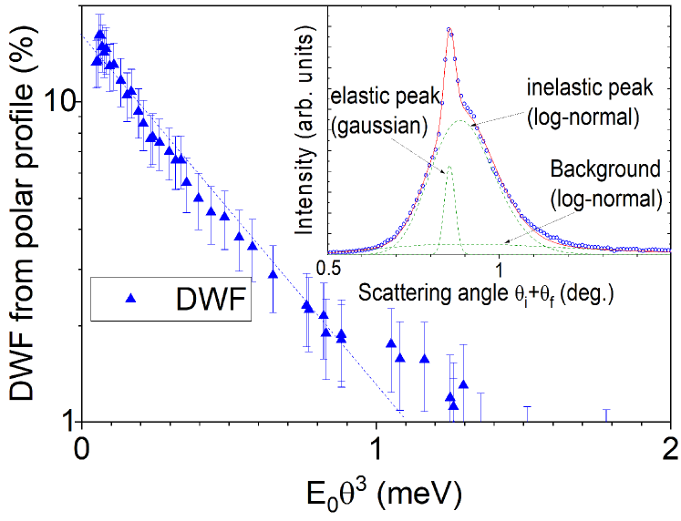
In Fig.6, we report the Debye-Waller factor (DWF) for neon atoms at 500 eV. The DWF is estimated here as the fraction of the elastic peak in the observed polar scattering profile, as detailed in Ref. [21] and shown in the inset of Fig. 6. This technique does not allow for a relevant estimate of the DWF below 1%, in part because the log-normal profile is not a perfect description [17], it is only the best available so far. The DWF is plotted as a function of , as suggested in Refs. [22, 23, 17] because this value corresponds to the classical energy loss in the multiple successive grazing collision regime of GIFAD. The quantity is expected to replace the binary recoil energy appearing in the standard DWF used in single scattering conditions such as X-ray, neutrons or thermal energy helium diffraction. In GIFAD, for helium projectile impinging on a LiF surface at room temperature, this 1% value of the DWF is reached with meV [24] while for the case of neon atoms, it is reached here between 1.1 and 1.3 meV. This is consistent with the fact that for comparable trajectory, all the binary classical energy transfers to the surface atoms should scale with the projectile mass.
More important for the analysis in the next sections, the fraction of elastic scattering on the Laue circle, and called contrast or visibility, is given by the relative height of the elastic Gaussian peak at its maximum. It is typically larger than the DWF. In the example in the inset of Fig. 6, the DWF is only 10% while the contrast (see in Table 1) at the specular position is close to 41%.
IV [Rnd] direction
The [Rnd] and [100] directions were recorded more recently with 1 keV neon atoms and a new detector [25]. The strategy to analyze the diffraction pattern has also evolved. Following Ref. [18], we use a line-shape (Table 1) which takes explicitly into account the primary beam resolution (here also of 9 mdeg) and the elastic ratio on the Laue circle so that the measured width parameter corresponds to that of the inelastic component only.
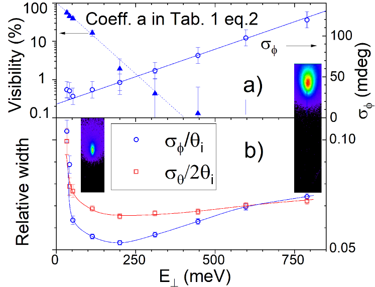
In the quantum regime, a random direction can be defined as a direction where only the specular peak () is present, indicating a surface seen as perfectly flat so that no structural information can be extracted (see e.g. Ref. [15]). In the present case, the exact direction was 10∘ away from the [100] direction. 2D images of the scattering profiles are displayed as insets in Fig. 7.
The dynamic information, which is the ratio of elastic to the total scattering intensity, identified here to the DWF and the inelastic polar () and azimuthal () profiles are comparatively easy to measure and are reported in Fig. 7a). The lines drawn to guide the eyes indicate that the visibility on the Laue circle drops by four orders of magnitude between an (extrapolated) incident perpendicular energy of 0 meV and 400 meV perpendicular energy. The inelastic lateral width increases linearly above 100 meV following approximately the equation 16 + 135 mdeg/eV. With helium and under restricted conditions, these polar and azimuthal profiles were identical, irrespective of the surface orientation [21, 26, 18].
V [100] direction
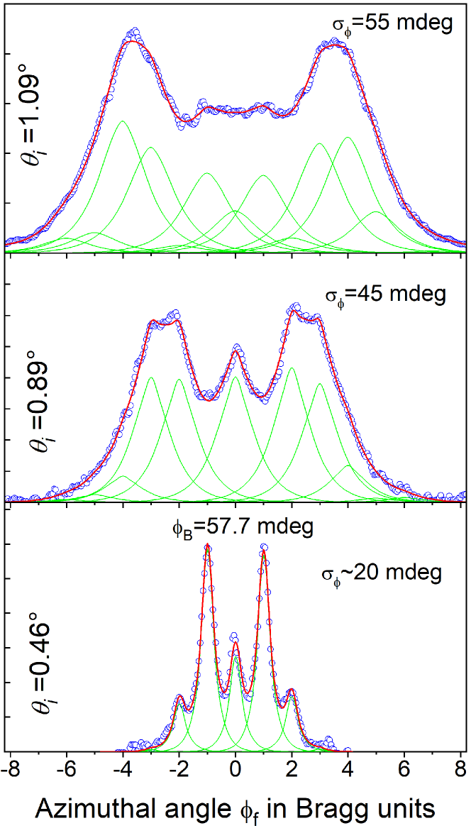
The diffraction profiles recorded in a -scan at 1 keV were fitted by lineshapes with and parameter taken from Fig. 7a) measured along the [Rnd] direction at same energy . There is obviously not enough data points in Fig. 7a) at low values of so that comparatively large values were selected in Fig. 8. The only parameter of the fits are the set of relative intensities but the quality appears reasonable, and the evolution of with reported in Fig. 9 resembles a typical evolution of Bessel function as expected from simple cosine corrugation function. Note that in Fig. 9 the intensity of the diffraction orders recorded at are so low that they are not visible whereas the associated energy of 240 meV is such that the elastic contribution on the Laue circle is only a few . It does not prove that the inelastic signal is fully coherent, but the coherent description with a lineshape broadened by inelastic effects seems to be a fair description of the progressive weakening of visible quantum features.
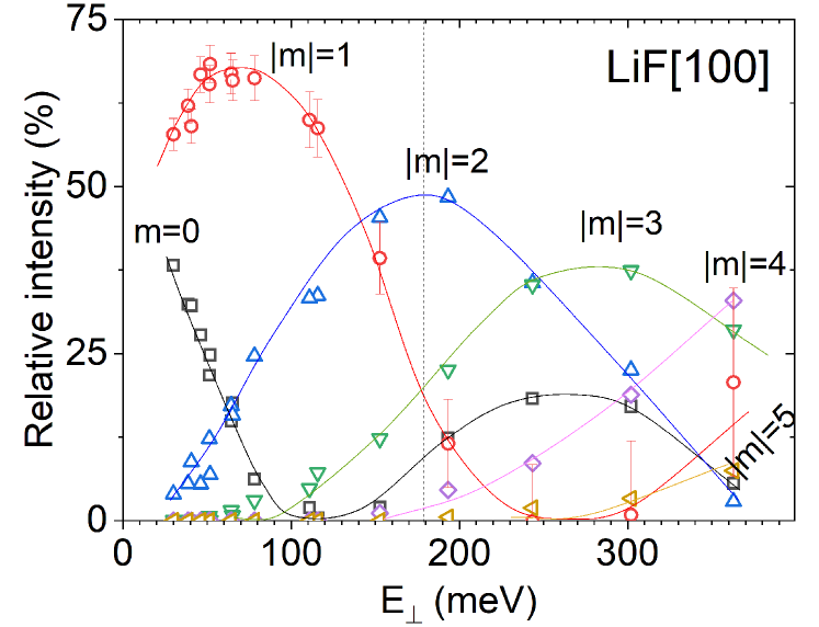
The vertical dotted line indicates the region beyond which the elastic contribution is less than 1%. Below this line, a self-consistent evaluation of with internally optimized diffraction profile would probably be possible. However, above this limit, a direct evaluation of the intensities without a priori information on the linewidth would have been questionable. It should also be outlined that at comparatively large incidence angle, the polar scattering profile becomes so large that selecting a narrow slice having a width close to that of the primary beam corresponds to a weak fraction of the intensity. In Fig. 8 the profile recorded at =1.09∘ corresponds to only 5% of the scattered intensity because the fully inelastic polar profile is 0.4∘ wide (fwhm). The size of the polar slice selected for the profile could be enlarged beyond because no elastic diffraction is visible, but not too much otherwise the contribution of different effective angles would smear the rapid evolution of . In particular, the ability to measure a weak value of a given diffraction order would be compromised by a simple averaging effect. We should also stress that the independence of the lateral profile to the surface orientation cannot be demonstrated beyond this line where individual peaks are not resolved. One can, at most, confirm that the profile measured along a [Rnd] direction offers a decent fit along [100] or [110] as illustrated below in Fig.8. However, this is not fully convincing evidence that the lineshapes are indeed identical since many overlapping lines contribute to a diffraction profile which becomes increasingly smooth as visible in top profiles in Fig. 3.
VI Discussion
In this section, we assume that the inelastic component originates only from the interaction with surface phonons [27, 28] along the projectile trajectory above the surface. Compared with helium, the large mass of neon strongly enhances the inelastic effect, so that its contribution cannot be neglected. Assuming that inelastic and elastic intensity ratios are identical on the Laue circle and that the lineshapes are identical for all surface orientations, we have produced diffracted intensities in conditions where no elastic diffraction is visible. We have no guarantee that these intensities are correct because the two starting assumptions were derived only in conditions where elastic diffraction is significant. The question can be turned differently, are the intensities derived from elastic and inelastic intensities always comparable or is this valid in a limited range?
This naive question has been present since the beginning of GIFAD. The elastic component corresponds to a surface with atoms fixed at equilibrium positions because this is the only configuration that offers perfectly periodic conditions. How is this idealized description connected with an actual surface where the atoms have a mass and undergo thermal motion? The answer is that the surface is not classical but quantum. The vibrations at surfaces are specific phonon modes that can be further simplified as independent harmonic oscillators using the Debye Model. The probability to leave a harmonic oscillator in its ground state, with wavefunction in response to a sudden momentum transfer is , known as the Lamb-Dicke probability or recoilless emission (or absorption) probability in atomic spectroscopy or in the cold atom community [29, 30]. If no excitation occurs, the scattering takes place from the center of the vibration wave-function which is indeed sitting at the equilibrium position in spite of a Gaussian thermal position distribution of variance that never reaches 0.
The question is now what do we see in inelastic diffraction? Starting with the observation that, when elastic diffraction is present and within a limited range around the Laue circle (typically ), the structural information derived from the inelastic profiles compares with the elastic one. Of course, an effective wavelength has to be defined but it was shown [13, 31] that using (Table 1) provides intensities comparable with the one derived from elastic diffraction at . A model was developed where inelastic diffraction is seen as a perturbation of the elastic trajectory. Among the N lattice sites encountered, each binary collision can turn inelastic (with a probability ), allowing a derivation of the DWF adapted to GIFAD [23, 22] and essentially confirmed by experiment at different temperatures [24]. On the other hand, the idea that the scattering profile could be decomposed in terms of the number of inelastic binary collisions, each contributing to a finite angular broadening was invalidated. Even at the lowest investigated angles, the agreement with the experimental inelastic polar profiles was reached [21] only with the classical limit where as if a single inelastic collision would turn all other collisions inelastic, as considered in case B of Ref. [22].
For temperatures below the Debye temperature, this should correspond to scattering from a surface where the surface atoms adopt a classical position distribution. In other words, the inelastic polar scattering distribution appears close to that arising from classical mechanics. In this case the intensities derived from inelastic conditions should be related to the thermally averaged surface, not the one at the equilibrium position. These are different in GIFAD because the diffraction takes place along the well-aligned rows on the effective 2D potential with any multiple of the lattice parameter along . Whether explicit [32] in a 2D calculation or implicit using a 3D trajectory [33], the integral or average in the effective 2D potential is not the same with surface atoms thermally displaced or at equilibrium position because of the exponential character of the potential along . One is temperature dependent while the ideal one measured in elastic diffraction is not. This is visible in Fig. 6 of Ref. [24] where recorded on the Laue circle in quasi elastic conditions at different temperatures fall on top of each other.
On the theoretical side, the rumpling of the Li+ ions was estimated by comparing with experimental values of . The value derived from an ideal surface model is 20 % less than that estimated from the thermally averaged surface [34]. Also in Ref. [35], depending on the surface representation used, the intensity calculated at the rainbow angle can vary by a factor of three to four, and some intensities can switch from intense to negligible [36]. These calculations are presented as elastic, but no sharp peak [16] is present and the scattering profiles compare with the one called here inelastic, possibly because the Lamb-Dicke effect is not properly taken into account. In addition, the inelastic effects are probably underestimated because the author introduces a restriction in the thermal amplitude [37, 38, 39] that is supposed to guarantee an elastic scattering.
It seems clear that, from the theoretical side, there are significant differences between the intensities derived from the ideal and the thermally averaged surfaces. Can the second one be associated with the experimental inelastic diffraction? The answer is probably yes when elastic diffraction has disappeared, but the answer could be progressive. The equivalence between from elastic and inelastic diffraction observed when both are present [17] appears in contradiction with the strict association inelastic-thermally averaged. These facts could be re-investigated in more detail, but a strong difference between elastic and inelastic values of would probably have been detected. The gradual evolution is also supported by the recent finding [18] that at low values of , where elastic diffraction is important, the polar angle dependence of the azimuthal inelastic width is linear with a minimum at the specular angle: where is the width at the specular angle . This could support a perturbative approach explaining that the elastic and inelastic intensities are identical on the Laue circle. However, this dependence rapidly becomes more complex progressively loosing memory of the specular position [18]. This could be a sign of inelastic diffraction starting to probe the thermally averaged surface, i.e. the one with classically distributed atoms. How fast or how progressive is the transition remains to be investigated both theoretically and experimentally, but no convincing model is available yet. It could be that inelastic effects start with long wavelength phonons, as suggested in a calculation trying to model a quantum surface [40], but no scattering distribution was presented.
It should also be mentioned that the inelastic component may have various origins, we have focused here on the phonon contribution but, most likely, a limited surface coherence is responsible for the absence of elastic diffraction in many experiments, including our first publications [32, 23, 20] and may also contribute partly as suggested by the fact that the DWF seems to saturate at the lowest values of [24]. The question of the nature of the defects limiting this surface coherence is difficult and probably important, ad-atoms may have different consequences on the inelastic profiles than missing atoms.
Note also that when important electronic excitations are present, such as LiF excitons [41] with an energy above 10 eV are excited, diffraction disappears [42]. For weaker electronic excitation such as the one at the Fermi level of a metal, the momentum exchanged could be less than a reciprocal lattice vector, allowing a contribution from electron system [43] in inelastic diffraction.
VII Summary and Conclusion
We have explored the line profile and DWF with neon projectile for which the inelastic effect are significantly larger than for helium. We have extracted diffracted intensities over a broad range of impact energy using the azimuthal profile recorded along a [Rnd] direction as a reference. From the point of view of data analysis, this seems to be an efficient technique however, when the profile becomes too broad, the uniqueness of the deconvolution is far from guaranteed, in particular in the quasi-specular region () where the oscillation of intensities with tend to be shifted [2, 9]. In this case, it would be more reasonable to provide an analytic form of the line shape so that comparison with independent theoretical predictions is possible after convolution by this form. The experiments should then provide both the diffraction profiles along a crystal axis and a reference profile recorded along the [Rnd] direction. This approach could also be used when the primary beam is slightly misaligned with the crystal axis. It is comparatively easy for the theory to take this misalignment into account [44, 2, 45] whereas correcting data is not easy and restricted to simple systems [46, 47]. The nature of the surface described by the diffracted intensities is unclear when these are recorded in inelastic conditions. It seems difficult to avoid considering that the thermally averaged atomic position should be considered under deeply inelastic conditions, but the experiment suggests that this might not be the case in the quasi-elastic regime, where elastic diffraction is important. The equivalence of the polar and azimuthal profiles, apparently valid in the quasi elastic regime, may not be valid when diffraction is completely inelastic with specific contributions from well localized trajectories inside the unit cell. More experimental and theoretical work is needed to better model the inelastic diffraction in GIFAD. There are obvious similarities with the multiphonon regime observed [48] and modelled [49] in thermal energy atomic scattering, but these remain to be investigated in the GIFAD context.
VIII Acknowledgment
We are grateful to Hynd Remita for the irradiation of the LiF samples by rays from the Cobalt source of the Institut de Chimie Physique at Orsay, favoring further cleaving along (001) planes with large terraces and observation of elastic diffraction. This work received support from LabEx PALM (ANR-10-LABX-0039-PALM) and Chinese Scholarship Council (CSC) Grant No. 201806180025.
References
- Atkinson et al. [2014] P. Atkinson, M. Eddrief, V. H. Etgens, H. Khemliche, M. Debiossac, A. Momeni, M. Mulier, B. Lalmi, and P. Roncin, Dynamic grazing incidence fast atom diffraction during molecular beam epitaxial growth of GaAs, Applied Physics Letters 105, 021602 (2014).
- Debiossac et al. [2014a] M. Debiossac, A. Zugarramurdi, H. Khemliche, P. Roncin, A. Borisov, A. Momeni, P. Atkinson, M. Eddrief, F. Finocchi, and V. H. Etgens, Combined experimental and theoretical study of fast atom diffraction on the reconstructed GaAs(001) surface, Phys. Rev. B 90, 155308 (2014a).
- Debiossac et al. [2017] M. Debiossac, P. Atkinson, A. Zugarramurdi, M. Eddrief, F. Finocchi, V. Etgens, A. Momeni, H. Khemliche, A. G. Borisov, and P. Roncin, Fast atom diffraction inside a molecular beam epitaxy chamber, a rich combination, Applied Surface Science 391, 53 (2017).
- Seifert et al. [2010] J. Seifert, A. Schüller, H. Winter, R. Włodarczyk, J. Sauer, and M. Sierka, Diffraction of fast atoms during grazing scattering from the surface of an ultrathin silica film on Mo (112), Phys. Rev. B 82, 035436 (2010).
- Zugarramurdi et al. [2015] A. Zugarramurdi, M. Debiossac, P. Lunca-Popa, A. J. Mayne, A. Momeni, A. G. Borisov, Z. Mu, P. Roncin, and H. Khemliche, Determination of the geometric corrugation of graphene on SiC(0001) by grazing incidence fast atom diffraction, App. Phys. Lett. 106, 101902 (2015).
- Seifert et al. [2013] J. Seifert, M. Busch, E. Meyer, and H. Winter, Surface structure of alanine on Cu (110) studied by fast atom diffraction, Physical Review Letters 111, 137601 (2013).
- Kalashnyk et al. [2016] N. Kalashnyk, H. Khemliche, and P. Roncin, Atom beam triangulation of organic layers at 100 meV normal energy: self-assembled perylene on Ag(110) at room temperature, Applied Surface Science 364, 235 (2016).
- Winter and Schüller [2011] H. Winter and A. Schüller, Fast atom diffraction during grazing scattering from surfaces, Progress in Surface Science 86, 169 (2011).
- Debiossac et al. [2021] M. Debiossac, P. Pan, and P. Roncin, Grazing incidence fast atom diffraction, similarities and differences with thermal energy atom scattering (TEAS), Phys. Chem. Chem. Phys. 11, 4564 (2021).
- Gravielle et al. [2011] M. Gravielle, A. Schüller, H. Winter, and J. Miraglia, Fast atom diffraction for grazing scattering of Ne atoms from a LiF(001) surface, NIM-B 269, 1208 (2011).
- Debiossac et al. [2020] M. Debiossac, P. Roncin, and A. G. Borisov, Refraction of fast Ne atoms in the attractive well of a LiF(001) surface, J. Phys. Chem. Lett. 11, 4564 (2020).
- Lalmi et al. [2012] B. Lalmi, H. Khemliche, A. Momeni, P. Soulisse, and P. Roncin, High resolution imaging of superficial mosaicity in single crystals using grazing incidence fast atom diffraction, J. Phys. Condens. Matter 24, 442002 (2012).
- Debiossac and Roncin [2016] M. Debiossac and P. Roncin, Image processing for grazing incidence fast atom diffraction, NIM-B 382, 36 (2016).
- Pan et al. [2022a] P. Pan, J. N. Rad, and P. Roncin, A setup for grazing incidence fast atom diffraction, Review of Scientific Instruments 93, 093305 (2022a).
- Zugarramurdi and Borisov [2012] A. Zugarramurdi and A. G. Borisov, Transition from fast to slow atom diffraction, Phys. Rev. A 86, 062903 (2012).
- [16] In principle, the projectile energy loss could be measured by time of flight [50] to identify the elastic peak and the phonon excitation. However, the required resolution of a few meV appears out of reach of present technology.
- Roncin and Debiossac [2017] P. Roncin and M. Debiossac, Elastic and inelastic diffraction of fast atoms, Debye-Waller factor, and Mössbauer-Lamb-Dicke regime, Phys. Rev. B 96, 035415 (2017).
- Pan et al. [2023] P. Pan, C. Kanitz, M. Debiossac, A. Le-Guen, J. N. Rad, and P. Roncin, Lateral line profiles in fast-atom diffraction at surfaces, Phys. Rev. B 108, 035413 (2023).
- Winter and Schüller [2005] H. Winter and A. Schüller, Rainbow scattering under axial surface channeling, NIM-B 232, 165 (2005).
- Momeni et al. [2010] A. Momeni, P. Soulisse, P. Rousseau, H. Khemliche, and P. Roncin, Grazing incidence fast atom diffraction (gifad): Doing RHEED with atoms, e-Journal of Surface Science and Nanotechnology 8, 101 (2010).
- Pan et al. [2021] P. Pan, M. Debiossac, and P. Roncin, Polar inelastic profiles in fast-atom diffraction at surfaces, Phys. Rev. B 104, 165415 (2021).
- Manson et al. [2008] J. R. Manson, H. Khemliche, and P. Roncin, Theory of grazing incidence diffraction of fast atoms and molecules from surfaces, Phys. Rev. B 78, 155408 (2008).
- Rousseau et al. [2008] P. Rousseau, H. Khemliche, N. Bundaleski, P. Soulisse, A. Momeni, and P. Roncin, Surface analysis with grazing incidence fast atom diffraction (GIFAD), Journal of Physics: Conf. Series 133, 012013 (2008).
- Pan et al. [2022b] P. Pan, M. Debiossac, and P. Roncin, Temperature dependence in fast-atom diffraction at surfaces, Phys. Chem. Chem. Phys. 24, 12319 (2022b).
- Lupone et al. [2018] S. Lupone, P. Soulisse, and P. Roncin, A large area high resolution imaging detector for fast atom diffraction, NIM-B 427, 95 (2018).
- Seifert et al. [2015] J. Seifert, J. Lienemann, A. Schüller, and H. Winter, Studies on coherence and decoherence in fast atom diffraction, NIM-B 350, 99 (2015).
- Al Taleb et al. [2017a] A. Al Taleb, G. Anemone, W. Hayes, J. Manson, and D. Farías, Multiphonon excitation and quantum decoherence in neon scattering from solid surfaces, Physical Review B 95, 075414 (2017a).
- Tamtögl et al. [2013] A. Tamtögl, P. Kraus, M. Mayrhofer-Reinhartshuber, D. Campi, M. Bernasconi, G. Benedek, and W. E. Ernst, Surface and subsurface phonons of Bi (111) measured with helium atom scattering, Physical Review B 87, 035410 (2013).
- Wineland et al. [1992] D. J. Wineland, J. Dalibard, and C. Cohen-Tannoudji, Sisyphus cooling of a bound atom, JOSA B 9, 32 (1992).
- Jurczak et al. [1996] C. Jurczak, B. Desruelle, K. Sengstock, J.-Y. Courtois, C. Westbrook, and A. Aspect, Atomic transport in an optical lattice: an investigation through polarization-selective intensity correlations, Phys. Rev. Lett. 77, 1727 (1996).
- Roncin et al. [2018] P. Roncin, M. Debiossac, H. Oueslati, and F. Raouafi, Energy loss and inelastic diffraction of fast atoms at grazing incidence, NIM-B 427, 100 (2018).
- Rousseau et al. [2007] P. Rousseau, H. Khemliche, A. G. Borisov, and P. Roncin, Quantum scattering of fast atoms and molecules on surfaces, Phys. Rev. Lett. 98, 016104 (2007).
- Muzas et al. [2016] A. Muzas, F. Gatti, F. Martín, and C. Díaz, Diffraction of H from LiF(001): From slow normal incidence to fast grazing incidence, NIM-B 382, 49 (2016).
- Schüller et al. [2010] A. Schüller, S. Wethekam, D. Blauth, H. Winter, F. Aigner, N. Simonović, B. Solleder, J. Burgdörfer, and L. Wirtz, Rumpling of LiF(001) surface from fast atom diffraction, Phys. Rev. A 82, 062902 (2010).
- Gravielle and Miraglia [2020] M. Gravielle and J. Miraglia, Phonon contribution to grazing incidence fast atom diffraction, in Journal of Physics: Conference Series, Vol. 1412 (IOP Publishing, 2020) p. 202009.
- Frisco and Gravielle [2023] L. Frisco and M. Gravielle, Decoherent phonon effects in fast atom-surface scattering, NIM-B 540, 1 (2023).
- Frisco and Gravielle [2019] L. Frisco and M. S. Gravielle, Phonon contribution in grazing-incidence fast atom diffraction from insulator surfaces, Phys. Rev. A 100, 062703 (2019).
- Frisco and Gravielle [2020] L. Frisco and M. S. Gravielle, Thermal effects on helium scattering from LiF (001) at grazing incidence, Phys. Rev. A 102, 062821 (2020).
- Díaz and Gravielle [2022] C. Díaz and M. S. Gravielle, Grazing incidence fast atom and molecule diffraction: theoretical challenges, Physical Chemistry Chemical Physics 24, 15628 (2022).
- Schram and Heller [2018] M. C. Schram and E. J. Heller, Approach to coherent interference fringes in helium-surface scattering, Phys. Rev. A 98, 022137 (2018).
- Roncin et al. [1999] P. Roncin, J. Villette, J. P. Atanas, and H. Khemliche, Energy loss of low energy protons on LiF(100): Surface excitation and mediated electron emission, Phys. Rev. Lett. 83, 864 (1999).
- Lienemann et al. [2011] J. Lienemann, A. Schüller, D. Blauth, J. Seifert, S. Wethekam, M. Busch, K. Maass, and H. Winter, Coherence during scattering of fast H atoms from a LiF (001) surface, Physical review letters 106, 067602 (2011).
- Bundaleski et al. [2011] N. Bundaleski, P. Soulisse, A. Momeni, H. Khemliche, and P. Roncin, Decoherence in fast atom diffraction from surfaces, NIM-B 269, 1216 (2011).
- Zugarramurdi et al. [2013] A. Zugarramurdi, M. Debiossac, P. Lunca-Popa, L. Alarcón, A. Momeni, H. Khemliche, P. Roncin, and A. G. Borisov, Surface-grating deflection of fast atom beams, Phys. Rev. A 88, 012904 (2013).
- Debiossac et al. [2014b] M. Debiossac, A. Zugarramurdi, P. Lunca-Popa, A. Momeni, H. Khemliche, A. G. Borisov, and P. Roncin, Transient quantum trapping of fast atoms at surfaces, Phys. Rev. Lett. 112, 023203 (2014b).
- Debiossac and Roncin [2014] M. Debiossac and P. Roncin, Atomic diffraction under oblique incidence: An analytical expression, Phys. Rev. A 90, 054701 (2014).
- Pollak and Miret-Artés [2015] E. Pollak and S. Miret-Artés, Second-order semiclassical perturbation theory for diffractive scattering from a surface, J. Phys. Chem. C 119, 14532 (2015).
- Al Taleb et al. [2017b] A. Al Taleb, G. Anemone, W. W. Hayes, J. R. Manson, and D. Farías, Multiphonon excitation and quantum decoherence in neon scattering from solid surfaces, Phys. Rev. B 95, 075414 (2017b).
- Manson [1991] J. Manson, Inelastic scattering from surfaces, Physical Review B 43, 6924 (1991).
- Holst et al. [2021] B. Holst, G. Alexandrowicz, N. Avidor, G. Benedek, G. Bracco, W. E. Ernst, D. Farías, A. P. Jardine, K. Lefmann, J. R. Manson, et al., Material properties particularly suited to be measured with helium scattering: selected examples from 2D materials, van der waals heterostructures, glassy materials, catalytic substrates, topological insulators and superconducting radio frequency materials, Physical Chemistry Chemical Physics 23, 7653 (2021).