Wideband Beamforming for STAR-RIS-assisted THz Communications with Three-Side Beam Split

Wencai Yan, Wanming Hao,  Gangcan Sun, Chongwen Huang, 
Qingqing Wu
W. Yan, W. Hao and G. Sun are with the School of Electrical and Information Engineering, Zhengzhou University, Zhengzhou 450001, China. (E-mail: yanwencai001@163.com, {iewmhao, iegcsun}@zzu.edu.cn).C. Huang is with College of Information Science and Electronic Engineering, Zhejiang University, Hangzhou 310027, China. (E-mail: chongwenhuang@zju.edu.cn).Q. Wu is with the Department of Electronic Engineering, Shanghai Jiao Tong University, Shanghai 201210, China. (E-mail: qingqingwu@sjtu.edu.cn).
Abstract

In this paper, we consider the simultaneously transmitting and reflecting reconfigurable intelligent surface (STAR-RIS)-assisted THz communications with three-side beam split. Except for the beam split at the base station (BS), we analyze the double-side beam split at the STAR-RIS for the first time. To relieve the double-side beam split effect, we propose a time delayer (TD)-based fully-connected structure at the STAR-RIS. As a further advance, a low-hardware complexity and low-power consumption sub-connected structure is developed, where multiple STAR-RIS elements share one TD. Meanwhile, considering the practical scenario, we investigate a multi-STAR-RIS and multi-user communication system, and a sum rate maximization problem is formulated by jointly optimizing the hybrid analog/digital beamforming, time delays at the BS as well as the double-layer phase-shift coefficients, time delays and amplitude coefficients at the STAR-RISs. Based on this, we first allocate users for each STAR-RIS, and then derive the analog beamforming, time delays at the BS, and the double-layer phase-shift coefficients, time delays at each STAR-RIS. Next, we develop an alternative optimization algorithm to calculate the digital beamforming at the BS and amplitude coefficients at the STAR-RISs. Finally, the numerical results verify the effectiveness of the proposed schemes.

Index Terms:
THz communication, Beam split effect, STAR-RIS, Beamforming design.

I Introduction

Terahertz (THz) has attracted great attention in future 6G networks due to its ultra-wide bandwidth [1][2]. However, the ultra-high frequency of THz signals results in the serious propagation loss, limiting the transmission distance [3]. Fortunately, massive multiple-input multiple-output (MIMO) is usually exploited to realize high-gain directional beams, which can effectively improve the coverage range of THz communications. Additionally, the traditional fully-digital antenna structure will bring huge power consumption and hardware complexity for THz massive MIMO communications. Therefore, the hybrid analog/digital antenna structure are usually applied [4][5].

Furthermore, THz communications exhibit the characteristic of poor diffraction, rendering it susceptible to signal blockages, and thus breaks the line-of-sight (LoS) link. As such, reconfigurable intelligent surface (RIS) [6][7] can be implemented to tackle this limitation, which is equipped with massive low-cost passive components. However, RIS is limited to reflecting incident wireless signals, requiring both the transmitter and receiver to be deployed on the same side of the RIS. To extend the scope of the coverage comprehensively, an innovative approach known as simultaneously transmitting and reflecting reconfigurable intelligent surfaces (STAR-RIS) is introduced [8]-[11]. STAR-RIS is able to concurrently transmit and reflect incident signals on both sides of the surface [12]. Moreover, each individual element of STAR-RIS applies two distinct and adjustable phase-shift values, catering to both the transmitted and reflected signals.

Therefore, it is promising to apply the STAR-RIS to THz communications. Whereas, due to the frequency-independent phase shifter (PS) at the BS and frequency-independent element at the STAR-RIS, there will exist beam split [13][14], seriously effecting the system performance. Consequently, in this paper, we mainly analyze the beam split and design the wideband beamforming in the STAR-RIS-assisted THz communications.

I-A Related Works

Several works have predominantly focused on addressing the beam split problem at the BS [15]-[19]. A fundamental solution is to replace all PSs with time delayer (TD) [16]. Unlike PS which produces a fixed phase across the entire bandwidth, the TD can provide a controllable time delay, inducing the different phase across overall frequencies. This frequency-dependent characteristic of TD effectively mitigates the beam split problem. However, replacing all PSs with TD is impractical, owing to the associated huge hardware costs within the THz band. Instead, an alternative approach proposed by [17]-[19] is to introduce a limited number of TDs between radio frequency (RF) chain and PSs so as to construct a TD-aided hybrid beamforming architecture. Specifically, in [17], authors introduced an energy-efficient fixed TD structure that deploys low-resolution discrete time delays. Although this scheme can effectively reduce the power consumption, it is unable to fully solve the beam split issue. In [18], authors presented a novel THzPrism architecture where TDs are arranged serially. Nevertheless, the hardware complexity of this architecture is high due to huge number of TDs. Furthermore, an effective delay-phase scheme was proposed in [19] to eliminate the beam split effect, where a few TDs insert between PSs and RF chains in parallel.

Recently, several works have considered the beam split problem at the RIS and investigated the wideband beamforming [20], [21]. Particularly, the association between the deployment of RIS and the beam split effect was analyzed in [21]. It is noteworthy that the methods employed in [20][21] still depend on the frequency-independent beamforming architectures, which is unable to solve the beam split of the RIS essentially. Taking a significant step forward, the authors in [22] analyzed the beam split effect based on far-field and near-field in THz RIS-assisted communications. To overcome the beam split effect, they introduced delay-adjustable metasurfaces at the RIS. Nevertheless, implementing delay-adjustable metasurfaces at each RIS element may be impractical due to the associated complexity. As a result, an element-grouping strategy of RIS was proposed in [23][24], and each sub-surface was equipped with a TD, which is capable of effectively mitigating the beam split effect. However, it is worth noting that [22][23] only considered the beam split at the RIS, while the beam split at the BS was not investigated. In [24], although the authors considered the beam split at both the BS and RIS, it is limited to the single-user scenario.

With the analysis above, there is no relevant study to jointly consider the beam split effect and beamforming optimization at the THz BS and STAR-RIS, which is challenging.

I-B Main Contributions

To mitigate the three-side beam split, we apply the limited number of TDs to both the BS and STAR-RIS. Then, the joint beamforming optimization problem is considered. The main contributions are summarized as follows:

  • \bullet

    We first analyze the double-side beam split effect at the STAR-RIS, and then propose a TD-aided fully-connected structure, where each STAR-RIS element adopts one PS and one TD to eliminate the beam split. As a further advance, we introduce a low-cost sub-connected structure, where each STAR-RIS element with double-layer PSs, and multiple STAR-RIS elements are divided into a sub-surface to share one common TD.

  • \bullet

    Next, we investigate the distributed STAR-RISs-assisted THz communications, where the TD-based hybrid analog/digital structure at the BS and the TD-based sub-connected structure at each SATR-RIS are considered, respectively. Based on this, a sum rate maximization problem is formulated by jointly optimizing the hybrid analog/digital beamforming, time delays at the BS as well as the double-layer phase-shift coefficients, time delays and amplitude coefficients at the STAR-RISs. To tackle this joint optimization problem, we first divide group for each STAR-RIS, and then derive the analog beamforming, time delays at the BS, and the double-layer phase-shift coefficients, time delays at each STAR-RIS. Finally, the original problem is transformed to a simplified problem to maximize the sum rate.

  • \bullet

    To solve the above transformed problem, an alternative iterative algorithm is proposed. Specifically, the digital beamforming at the BSs and the amplitude coefficients at the STAR-RISs are first decoupled by lagrangian dual reformulation (LDR) and multidimensional complex quadratic transform (MCQT). Next, by alternatively tackling the separated quadratically constrained quadratic program (QCQP) subproblems, the final solutions are obtained. In addition, we also provide the analysis with the robustness of the joint wideband beamforming framework versus the impacts of imperfect channel state information (CSI).

Notations: Lower-case, bold-face lowercase and bold-face uppercase boldface represent as scalar, vector and matrix, respectively. ()Tsuperscript𝑇(\cdot)^{{T}} indicates the transpose. ()Hsuperscript𝐻(\cdot)^{{H}} indicates the Hermitian transpose. diag()diag\rm diag(\cdot) is a diagonal matrix. tensor-product\otimes represents the Kronecker product. Tr{}Tr\operatorname{Tr}\{\cdot\} means the trace of its argument. |||\cdot| is the modulus of a complex number. \left\|\cdot\right\| represents the Frobenius norm of matrix. ln()\ln(\cdot) denotes natural logarithm. 𝐈Nsubscript𝐈𝑁\mathbf{I}_{N} denotes the N×N𝑁𝑁N\times N identity matrix. x×ysuperscript𝑥𝑦\mathbb{C}^{x\times y} is the space of x×y𝑥𝑦x\times y complex matrix. Re()Re\rm{Re}(\cdot) represents the real component of a complex number. 𝔼{}𝔼\mathbb{E}\{\cdot\} is the expectation operator.

II Beam Split Effect Analysis and STAR-RIS Structure Design

In this section, the double-side beam split at the STAR-RIS is first analyzed. Then, we employ a TD-based fully-connected structure at the STAR-RIS to mitigate the double-side beam split effect. Meanwhile, a low-cost sub-connected structure is developed.

II-A Beam Split Effect Analysis

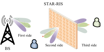
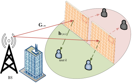
As shown in Fig. 1, there are three-side beam split in the STAR-RIS-assisted THz communications system. Actually, there exist several studies investigating the beam split effect at the BS. Thus, we emit this analysis, and more details can refer to [13][17]. Next, we mainly focus on analyzing the double-side beam split at the STAR-RIS. Let \mathbb{R} and 𝕋𝕋\mathbb{T} represent reflection and transmission side, respectively. To simplify the expression, we assume that the BS owns single antenna and the STAR-RIS consists of NRIS=N1N2subscript𝑁RISsubscript𝑁1subscript𝑁2N_{\rm RIS}=N_{1}N_{2} elements, where N1subscript𝑁1N_{1} and N2subscript𝑁2N_{2} are the number of rows and columns, respectively. In this paper, it is assumed that the direct links between the BS and users are blocked by obstacles. Meanwhile, the perfect CSIs of all links are assumed to be available by existing advanced channel acquisition methods [25]-[28]. The orthogonal frequency division multiplexing (OFDM) technique with M𝑀M subcarriers is adopted to address the frequency selective fading [29]. Denote B𝐵B as the bandwidth and fcsubscript𝑓𝑐f_{c} as the central frequency, and thus the frequency at the m𝑚m-th subcarrier is fm=fc+BM(m1M12),m=1,2,,Mformulae-sequencesubscript𝑓𝑚subscript𝑓𝑐𝐵𝑀𝑚1𝑀12𝑚12𝑀f_{m}=f_{c}+\frac{B}{M}\left(m-1-\frac{M-1}{2}\right),m=1,2,\cdots,M.

Refer to caption
Fig. 1: STAR-RIS-assisted THz communications with three-side beam split.

Generally, the communication channel consists of a LoS path and a few non-LoS (NLoS) paths [30]. However, due to the property of THz signals, the LoS path is usually dominated, hence we assume that only LoS path exists here [3][24]. Thus, the channel matrix 𝐆msubscript𝐆𝑚\mathbf{G}_{m} between the BS and STAR-RIS is given by

𝐆m=α1ej2πt1fm𝐛(fm,u1,v1),subscript𝐆𝑚subscript𝛼1superscript𝑒𝑗2𝜋subscript𝑡1subscript𝑓𝑚𝐛subscript𝑓𝑚subscript𝑢1subscript𝑣1\displaystyle\mathbf{G}_{m}=\alpha_{1}e^{-j2\pi t_{1}f_{m}}\mathbf{b}\left(f_{m},u_{1},v_{1}\right), (1)

where t1subscript𝑡1t_{1} and α1subscript𝛼1\alpha_{1} are the path delay and gain from the BS to the STAR-RIS, respectively. Specifically, the path gain is

α1(fm,d1)=c4πfmd1e12κabs(fm)d1,subscript𝛼1subscript𝑓𝑚subscript𝑑1c4𝜋subscript𝑓𝑚subscript𝑑1superscript𝑒12subscript𝜅𝑎𝑏𝑠subscript𝑓𝑚subscript𝑑1\displaystyle\alpha_{1}\left(f_{m},d_{1}\right)=\frac{\mathrm{c}}{4\pi f_{m}d_{1}}e^{-\frac{1}{2}\kappa_{abs}\left(f_{m}\right)d_{1}}, (2)

where c𝑐c, κabs(fm)subscript𝜅𝑎𝑏𝑠subscript𝑓𝑚\kappa_{abs}(f_{m}) and d1subscript𝑑1d_{1} denote the speed of light, medium absorption factor and distance from the BS to STAR-RIS, respectively. Besides, 𝐛(fm,u1,v1)𝐛subscript𝑓𝑚subscript𝑢1subscript𝑣1\mathbf{b}\left(f_{m},u_{1},v_{1}\right) represents the steering vector of the STAR-RIS, which is written as [31]

𝐛(fm,u1,v1)=1NRIS[1,,ejπξm(n1sinu1sinv1+n2cosv1),,ejπξm((N11)sinu1sinv1+(N21)cosv1)]T,𝐛subscript𝑓𝑚subscript𝑢1subscript𝑣11subscript𝑁RISsuperscript1superscript𝑒𝑗𝜋subscript𝜉𝑚subscript𝑛1subscript𝑢1subscript𝑣1subscript𝑛2subscript𝑣1superscript𝑒𝑗𝜋subscript𝜉𝑚subscript𝑁11subscript𝑢1subscript𝑣1subscript𝑁21subscript𝑣1𝑇\displaystyle\begin{split}\!\!\mathbf{b}\left(f_{m},u_{1},v_{1}\right)&=\frac{1}{\sqrt{N_{\rm{RIS}}}}[1,\ldots,e^{j\pi\xi_{m}(n_{1}\sin u_{1}\sin v_{1}+n_{2}\cos v_{1})},\\ &\ldots,e^{j\pi\xi_{m}((N_{1}-1)\sin u_{1}\sin v_{1}+(N_{2}-1)\cos v_{1})}]^{T},\end{split} (3)

where ξm=fmfcsubscript𝜉𝑚subscript𝑓𝑚subscript𝑓𝑐\xi_{m}=\frac{f_{m}}{f_{c}} is the relative frequency, u1[π/2,π/2]subscript𝑢1𝜋2𝜋2u_{1}\in[-\pi/2,\pi/2] and v1[0,π]subscript𝑣10𝜋v_{1}\in[0,\pi] are the azimuth and elevation angles of arrival (AOA) of the STAR-RIS, respectively.

Similarly, the channel vector 𝐡m,isubscript𝐡𝑚𝑖\mathbf{h}_{m,i} between the STAR-RIS and reflection/transmission user is expressed as

𝐡m,i=αiej2πtifm𝐛(fm,ui,vi)T,i{,𝕋},formulae-sequencesubscript𝐡𝑚𝑖subscript𝛼𝑖superscript𝑒𝑗2𝜋subscript𝑡𝑖subscript𝑓𝑚𝐛superscriptsubscript𝑓𝑚subscript𝑢𝑖subscript𝑣𝑖𝑇for-all𝑖𝕋\displaystyle\mathbf{h}_{m,i}=\alpha_{i}e^{-j2\pi t_{i}f_{m}}\mathbf{b}\left(f_{m},u_{i},v_{i}\right)^{T},\forall i\in\{\mathbb{R},\mathbb{T}\}, (4)

where tisubscript𝑡𝑖t_{i} and αisubscript𝛼𝑖\alpha_{i} represent the path delay and gain from the STAR-RIS to reflection/transmission user, respectively. The path gain αisubscript𝛼𝑖\alpha_{i} is modeled as

αi(fm,di)=c4πfmdie12κabs(fm)di,subscript𝛼𝑖subscript𝑓𝑚subscript𝑑𝑖c4𝜋subscript𝑓𝑚subscript𝑑𝑖superscript𝑒12subscript𝜅𝑎𝑏𝑠subscript𝑓𝑚subscript𝑑𝑖\displaystyle\alpha_{i}\left(f_{m},d_{i}\right)=\frac{\mathrm{c}}{4\pi f_{m}d_{i}}e^{-\frac{1}{2}\kappa_{abs}\left(f_{m}\right)d_{i}}, (5)

where disubscript𝑑𝑖d_{i} is the distance. ui[π/2,π/2]subscript𝑢𝑖𝜋2𝜋2u_{i}\in[-\pi/2,\pi/2] and vi[0,π]subscript𝑣𝑖0𝜋v_{i}\in[0,\pi] denote the azimuth and elevation angle of departure (AoD) at the STAR-RIS, respectively.

Based on the system model, the reflection/transmission normalized array gain gcon,i(fm)subscriptgcon𝑖subscript𝑓𝑚\mathrm{g}_{\mathrm{con},i}\left(f_{m}\right), i{,𝕋}for-all𝑖𝕋\forall i\in\{\mathbb{R},\mathbb{T}\} of the STAR-RIS with conventional structure on the m𝑚m-th subcarrier is computed as

gcon,i(fm)=|𝐛(fm,ui,vi)T𝚽i𝐛(fm,u1,v1)|=1NRIS|n1=0N11n2=0N21ejπξm[n1(ςi+ς1)+n2(ηi+η1)]ejϕi,n|,missing-subexpressionsubscriptgcon𝑖subscript𝑓𝑚𝐛superscriptsubscript𝑓𝑚subscript𝑢𝑖subscript𝑣𝑖𝑇subscript𝚽𝑖𝐛subscript𝑓𝑚subscript𝑢1subscript𝑣1missing-subexpressionabsent1subscript𝑁RISsuperscriptsubscriptsubscriptn10subscript𝑁11superscriptsubscriptsubscriptn20subscript𝑁21superscript𝑒𝑗𝜋subscript𝜉𝑚delimited-[]subscript𝑛1subscript𝜍𝑖subscript𝜍1subscript𝑛2subscript𝜂𝑖subscript𝜂1superscript𝑒𝑗subscriptitalic-ϕ𝑖𝑛\displaystyle\begin{aligned} &\mathrm{g}_{\mathrm{con},i}\left(f_{m}\right)=\left|\mathbf{b}\left(f_{m},u_{i},v_{i}\right)^{T}\mathbf{\Phi}_{i}\mathbf{b}\left(f_{m},u_{1},v_{1}\right)\right|\\ &=\frac{1}{N_{\mathrm{RIS}}}\left|\sum_{\mathrm{n}_{1}=0}^{N_{1}-1}\sum_{\mathrm{n}_{2}=0}^{N_{2}-1}e^{j\pi\xi_{m}\left[n_{1}(\varsigma_{i}+\varsigma_{1})+n_{2}(\eta_{i}+\eta_{1})\right]}\cdot e^{j\phi_{i,n}}\right|,\end{aligned} (6)

where n=N2n1+n2+1𝑛subscript𝑁2subscript𝑛1subscript𝑛21n=N_{2}n_{1}+n_{2}+1, ςi=sinuisinvisubscript𝜍𝑖subscript𝑢𝑖subscript𝑣𝑖\varsigma_{i}=\sin u_{i}\sin v_{i}, ς1=sinu1sinv1subscript𝜍1subscript𝑢1subscript𝑣1\varsigma_{1}=\sin u_{1}\sin v_{1}, ηi=cosuisubscript𝜂𝑖subscript𝑢𝑖\eta_{i}=\cos u_{i}, η1=cosu1subscript𝜂1subscript𝑢1\eta_{1}=\cos u_{1}. Besides, 𝚽i=diag(φi,1,,φi,NRIS)subscript𝚽𝑖diagsubscript𝜑𝑖1subscript𝜑𝑖subscript𝑁RIS\mathbf{\Phi}_{i}=\operatorname{diag}\left(\varphi_{i,1},\cdots,\varphi_{i,N_{\rm{RIS}}}\right) denotes the reflection/transmission coefficient of the STAR-RIS with φi,n=βi,nejϕi,nsubscript𝜑𝑖𝑛subscript𝛽𝑖𝑛superscript𝑒𝑗subscriptitalic-ϕ𝑖𝑛\varphi_{i,n}=\beta_{i,n}e^{j\phi_{i,n}}, where βi,n[0,1]subscript𝛽𝑖𝑛01\beta_{i,n}\in[0,1] and ϕi,n[0,2π)subscriptitalic-ϕ𝑖𝑛02𝜋\phi_{i,n}\in[0,2\pi) represent the reflection/transmission amplitude and phase, respectively. Moreover, we assume that the reflection/transmission amplitude βi,nsubscript𝛽𝑖𝑛\beta_{i,n} takes an arbitrary constant in this subsection, while satisfying the energy conservation constraint.

Refer to caption
Fig. 2: ​Normalized array gain under different bandwidths.

To generate a beam at target direction, we formulate the reflection/transmission phase-shift of the STAR-RIS on the basis of the center frequency fcsubscript𝑓𝑐f_{c}, which can be obtained by

ϕi,n=π[n1(ςi+ς1)+n2(ηi+η1)].subscriptitalic-ϕ𝑖𝑛𝜋delimited-[]subscript𝑛1subscript𝜍𝑖subscript𝜍1subscript𝑛2subscript𝜂𝑖subscript𝜂1\displaystyle\phi_{i,n}=-\pi\left[n_{1}(\varsigma_{i}+\varsigma_{1})+n_{2}(\eta_{i}+\eta_{1})\right]. (7)

It can be found that the generated beams can toward to the target direction at the center frequency fcsubscript𝑓𝑐f_{c}. However, at other frequency fmsubscript𝑓𝑚f_{m} with ξm1subscript𝜉𝑚1\xi_{m}\neq 1, the generated beams deviate from the target direction, which causes significant array gain loss as the normalized array gain gcon,i(fm)subscriptgcon𝑖subscript𝑓𝑚\mathrm{g}_{\mathrm{con},i}\left(f_{m}\right) fails to reach its maximum value at most frequencies. Thus, we can obtain

gcon,i(fm)=1NRIS|n1=0N11n2=0N21ejπ(ξm1)[n1(ςi+ς1)+n2(ηi+η1)]|=1NRIS|ΞN1((ξm1)(ςi+ς1))ΞN2((ξm1)(ηi+η1))|,subscriptgcon𝑖subscript𝑓𝑚1subscript𝑁RISsuperscriptsubscriptsubscriptn10subscript𝑁11superscriptsubscriptsubscriptn20subscript𝑁21superscript𝑒𝑗𝜋subscript𝜉𝑚1delimited-[]subscript𝑛1subscript𝜍𝑖subscript𝜍1subscript𝑛2subscript𝜂𝑖subscript𝜂11subscript𝑁RISsubscriptΞsubscript𝑁1subscript𝜉𝑚1subscript𝜍𝑖subscript𝜍1subscriptΞsubscript𝑁2subscript𝜉𝑚1subscript𝜂𝑖subscript𝜂1\begin{split}&\mathrm{g}_{\mathrm{con},i}\left(f_{m}\right)=\frac{1}{N_{\mathrm{RIS}}}\left|\sum_{\mathrm{n}_{1}=0}^{N_{1}-1}\sum_{\mathrm{n}_{2}=0}^{N_{2}-1}e^{j\pi(\xi_{m}-1)\left[n_{1}(\varsigma_{i}+\varsigma_{1})+n_{2}(\eta_{i}+\eta_{1})\right]}\right|\\ &=\frac{1}{N_{\mathrm{RIS}}}\left|\Xi_{N_{1}}\left(\left(\xi_{m}-1\right)(\varsigma_{i}+\varsigma_{1})\right)\Xi_{N_{2}}\left(\left(\xi_{m}-1\right)(\eta_{i}+\eta_{1})\right)\right|,\end{split} (8)

where Σn=0N1ejnπx=sinNπ2xsinπ2xej(N1)π2xsuperscriptsubscriptΣ𝑛0𝑁1superscript𝑒𝑗𝑛𝜋𝑥𝑁𝜋2𝑥𝜋2𝑥superscript𝑒𝑗𝑁1𝜋2𝑥\Sigma_{n=0}^{N-1}e^{jn\pi x}=\frac{\sin\frac{N\pi}{2}x}{\sin\frac{\pi}{2}x}e^{-j\frac{(N-1)\pi}{2}x} and ΞN(x)=sinNπ2xsinπ2xsubscriptΞ𝑁𝑥𝑁𝜋2𝑥𝜋2𝑥\Xi_{N}\left(x\right)=\frac{\sin\frac{N\pi}{2}x}{\sin\frac{\pi}{2}x}.

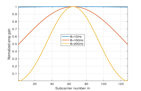
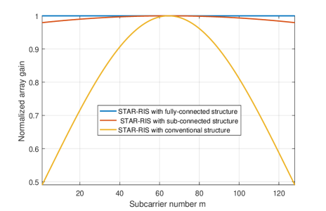
To further illustrate the beam split effect, we provide the normalized array gain under different bandwidths in Fig. 2. We set fc=100subscript𝑓𝑐100f_{c}=100 GHz, M=128𝑀128M=128 and NRIS=256subscript𝑁RIS256N_{\rm RIS}=256. It can be found that the array gain loss increases with the bandwidth. As a consequence, the benefits of utilizing the STAR-RIS and wideband THz resources are offset by beam split effect.

Refer to caption
Refer to caption
Fig. 3: (a) STAR-RIS with fully-connected structure, (b) STAR-RIS with sub-connected structure.

II-B STAR-RIS Structure Design

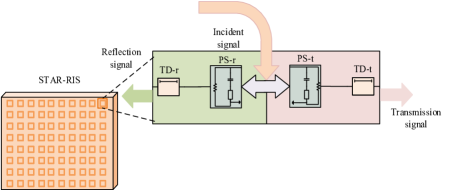
To overcome the double-side beam split effect of the STAR-RIS, we first propose a TD-based fully-connected structure as presented in Fig. 3(a), where each of STAR-RIS element is introduced with a reflection/transmission PS and a reflection/transmission TD, ie., PS-r/PS-t and TD-r/TD-t. Thus, the reflection/transmission normalized array gain gfully,i(fm),i{,𝕋}subscriptgfully𝑖subscript𝑓𝑚for-all𝑖𝕋\mathrm{g}_{\mathrm{fully},i}(f_{m}),\forall i\in\{\mathbb{R},\mathbb{T}\} of the STAR-RIS with fully-connected structure on the m𝑚m-th subcarrier is computed by

gfully,i(fm)=|𝐛(fm,ui,vi)T𝐓m,i𝚽i𝐛(fm,u1,v1)|=1NRIS|n1=0N11n2=0N21ejπξm[n1(ςi+ς1)+n2(ηi+η1)]ej(ϕi,n2πfmτi,n)|,subscriptgfully𝑖subscript𝑓𝑚𝐛superscriptsubscript𝑓𝑚subscript𝑢𝑖subscript𝑣𝑖𝑇subscript𝐓𝑚𝑖subscript𝚽𝑖𝐛subscript𝑓𝑚subscript𝑢1subscript𝑣11subscript𝑁RISsuperscriptsubscriptsubscriptn10subscript𝑁11superscriptsubscriptsubscriptn20subscript𝑁21superscript𝑒𝑗𝜋subscript𝜉𝑚delimited-[]subscript𝑛1subscript𝜍𝑖subscript𝜍1subscript𝑛2subscript𝜂𝑖subscript𝜂1superscript𝑒𝑗subscriptitalic-ϕ𝑖𝑛2𝜋subscript𝑓𝑚subscript𝜏𝑖𝑛\begin{split}&\mathrm{g}_{\mathrm{fully},i}\left(f_{m}\right)=\left|\mathbf{b}\left(f_{m},u_{i},v_{i}\right)^{T}\mathbf{T}_{m,i}\mathbf{\Phi}_{i}\mathbf{b}\left(f_{m},u_{1},v_{1}\right)\right|\\ &=\frac{1}{N_{\mathrm{RIS}}}\left|\sum_{\mathrm{n}_{1}=0}^{N_{1}-1}\sum_{\mathrm{n}_{2}=0}^{N_{2}-1}e^{j\pi\xi_{m}\left[n_{1}(\varsigma_{i}+\varsigma_{1})+n_{2}(\eta_{i}+\eta_{1})\right]}\cdot e^{j(\phi_{i,n}-2\pi f_{m}\tau_{i,n})}\right|,\end{split} (9)

where n=N2n1+n2+1𝑛subscript𝑁2subscript𝑛1subscript𝑛21n=N_{2}n_{1}+n_{2}+1, 𝐓m,i=diag(ej2πfm𝝉i)subscript𝐓𝑚𝑖diagsuperscript𝑒𝑗2𝜋subscript𝑓𝑚subscript𝝉𝑖\mathbf{T}_{m,i}=\operatorname{diag}(e^{-j2\pi f_{m}\bm{\tau}_{i}}) is the reflection/transmission time delay matrix on the m𝑚m-th subcarrier with 𝝉i=[τi,1,τi,2,,τi,NRIS]Tsubscript𝝉𝑖superscriptsubscript𝜏𝑖1subscript𝜏𝑖2subscript𝜏𝑖subscript𝑁RIS𝑇\bm{\tau}_{i}=\left[\tau_{i,1},\tau_{i,2},\ldots,\tau_{i,N_{\mathrm{RIS}}}\right]^{T}. To obtain maximum normalized array gain gfully,i(fm)subscriptgfully𝑖subscript𝑓𝑚\mathrm{g}_{\mathrm{fully},i}(f_{m}) over all frequencies, τi,nsubscript𝜏𝑖𝑛\tau_{i,n} is designed as

τi,n=12fc[n1(ςi+ς1)+n2(ηi+η1)],subscript𝜏𝑖𝑛12subscript𝑓𝑐delimited-[]subscript𝑛1subscript𝜍𝑖subscript𝜍1subscript𝑛2subscript𝜂𝑖subscript𝜂1\displaystyle\tau_{i,n}=\frac{1}{2f_{c}}[n_{1}(\varsigma_{i}+\varsigma_{1})+n_{2}(\eta_{i}+\eta_{1})], (10)

and ϕi,nsubscriptitalic-ϕ𝑖𝑛\phi_{i,n} can be set to arbitrary constants.

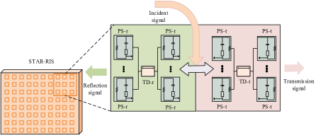
Consequently, the generated beams of the STAR-RIS with fully-connected structure will be perfectly steered to the target across the entire frequencies and thus the beam split is mitigated completely. Nonetheless, the cost and power consumption of TDs are much higher than that of PSs [32]. To further trade off the hardware cost and performance, we introduce a more cost-effective sub-connected structure, as presented in Fig. 3(b). To be specific, each side of the STAR-RIS element adopts double-layer PSs, and multiple STAR-RIS elements are combined into a sub-surface to share one TD. The first layer PS-r/PS-t is used to adjust the phase difference of the signals, and the second PS-r/PS-t is used to form beam. In this paper, the STAR-RIS is divided into S=S1S2𝑆subscript𝑆1subscript𝑆2S=S_{1}S_{2} sub-surfaces. Each sub-surface consists of L=L1L2𝐿subscript𝐿1subscript𝐿2L=L_{1}L_{2} elements, where L1=N1/S1subscript𝐿1subscript𝑁1subscript𝑆1L_{1}=N_{1}/S_{1}, L2=N2/S2subscript𝐿2subscript𝑁2subscript𝑆2L_{2}=N_{2}/S_{2}. We denote τi,ssubscript𝜏𝑖𝑠\tau_{i,s}, 𝚽i,1,ssubscript𝚽𝑖1𝑠\bm{\Phi}_{i,1,s} and 𝚽i,2,ssubscript𝚽𝑖2𝑠\bm{\Phi}_{i,2,s}, i{,𝕋}for-all𝑖𝕋\forall i\in\{\mathbb{R},\mathbb{T}\}, as the time delay, first-layer and second-layer phase-shift at the s𝑠s-th sub-surface of reflection/transmission side, respectively, where s=s1S2+s2+1𝑠subscript𝑠1subscript𝑆2subscript𝑠21s=s_{1}S_{2}+s_{2}+1. Then, the reflection/transmission array gain gsub,i(fm),i{,𝕋}subscriptgsub𝑖subscript𝑓𝑚for-all𝑖𝕋\mathrm{g}_{\mathrm{sub},i}(f_{m}),\forall i\in\{\mathbb{R},\mathbb{T}\} of the STAR-RIS with sub-connected structure on the m𝑚m-th subcarrier is computed by

gsub,i(fm)=|s1=0S11s2=0S21{l1=0L11l2=0L21𝐡m,i,s[𝚽i,2,sej2πfmτi,sl1=0L11l2=0L21𝚽i,1,s𝐆m,s]}|,\displaystyle\begin{aligned} &\mathrm{g}_{\mathrm{sub},i}\left(f_{m}\right)=\left|\sum_{s_{1}=0}^{S_{1}-1}\sum_{s_{2}=0}^{S_{2}-1}\right.\\ &\left.\!\!\!\!\left\{\sum_{l_{1}=0}^{L_{1}-1}\sum_{l_{2}=0}^{L_{2}-1}\mathbf{h}_{m,i,s}\left[\bm{\Phi}_{i,2,s}e^{-j2\pi f_{m}\tau_{i,s}}\sum_{l_{1}=0}^{L_{1}-1}\sum_{l_{2}=0}^{L_{2}-1}\bm{\Phi}_{i,1,s}\mathbf{G}_{m,s}\right]\right\}\right|,\end{aligned} (11)

where 𝐆m,ssubscript𝐆𝑚𝑠\mathbf{G}_{m,s} and 𝐡m,i,ssubscript𝐡𝑚𝑖𝑠\mathbf{h}_{m,i,s} denote the channel from the BS to STAR-RIS and from the STAR-RIS to reflection/transmission user at s𝑠s-th sub-surface on the m𝑚m-th subcarrier, respectively. Next, we optimize τi,ssubscript𝜏𝑖𝑠\tau_{i,s}, 𝚽i,1,ssubscript𝚽𝑖1𝑠\bm{\Phi}_{i,1,s} and 𝚽i,2,ssubscript𝚽𝑖2𝑠\bm{\Phi}_{i,2,s} to maximize the reflection/transmission array gain of the STAR-RIS on the m𝑚m-th subcarrier. Due to l1=0L11l2=0L21𝚽i,1,s𝐆m,ssuperscriptsubscriptsubscript𝑙10subscript𝐿11superscriptsubscriptsubscript𝑙20subscript𝐿21subscript𝚽𝑖1𝑠subscript𝐆𝑚𝑠\sum_{l_{1}=0}^{L_{1}-1}\sum_{l_{2}=0}^{L_{2}-1}\bm{\Phi}_{i,1,s}\mathbf{G}_{m,s} is a scalar, maximizing gsub,i(fm)subscriptgsub𝑖subscript𝑓𝑚\mathrm{g}_{\mathrm{sub},i}\left(f_{m}\right) can be divided into two subproblems, namely

maxl1=0L11l2=0L21𝚽i,1,s𝐆m,s,superscriptsubscriptsubscript𝑙10subscript𝐿11superscriptsubscriptsubscript𝑙20subscript𝐿21subscript𝚽𝑖1𝑠subscript𝐆𝑚𝑠\displaystyle\max\sum_{l_{1}=0}^{L_{1}-1}\sum_{l_{2}=0}^{L_{2}-1}\bm{\Phi}_{i,1,s}\mathbf{G}_{m,s}, (12)

and

maxl1=0L11l2=0L21𝐡m,i,s𝚽i,2,s.superscriptsubscriptsubscript𝑙10subscript𝐿11superscriptsubscriptsubscript𝑙20subscript𝐿21subscript𝐡𝑚𝑖𝑠subscript𝚽𝑖2𝑠\displaystyle\max\sum_{l_{1}=0}^{L_{1}-1}\sum_{l_{2}=0}^{L_{2}-1}\mathbf{h}_{m,i,s}\bm{\Phi}_{i,2,s}. (13)

The (l1,l2)subscript𝑙1subscript𝑙2(l_{1},l_{2})-th element of 𝐆m,ssubscript𝐆𝑚𝑠\mathbf{G}_{m,s} is written as

𝐆m,s,(l1,l2)=α1NRISej2πt1fmejπξm(n1ς1+n2η1)=α1NRISej2πt1fmejπξm((s1L1+l1)ς1+(s2L2+l2)η1)=α1NRISej2πt1fmejπξm(s1L1ς1+s2L2η1)ejπξm(l1ς1+l2η1),missing-subexpressionsubscript𝐆𝑚𝑠subscript𝑙1subscript𝑙2subscript𝛼1subscript𝑁RISsuperscript𝑒𝑗2𝜋subscript𝑡1subscript𝑓𝑚superscript𝑒𝑗𝜋subscript𝜉𝑚subscript𝑛1subscript𝜍1subscript𝑛2subscript𝜂1missing-subexpressionabsentsubscript𝛼1subscript𝑁RISsuperscript𝑒𝑗2𝜋subscript𝑡1subscript𝑓𝑚superscript𝑒𝑗𝜋subscript𝜉𝑚subscript𝑠1subscript𝐿1subscript𝑙1subscript𝜍1subscript𝑠2subscript𝐿2subscript𝑙2subscript𝜂1missing-subexpressionabsentsubscript𝛼1subscript𝑁RISsuperscript𝑒𝑗2𝜋subscript𝑡1subscript𝑓𝑚superscript𝑒𝑗𝜋subscript𝜉𝑚subscript𝑠1subscript𝐿1subscript𝜍1subscript𝑠2subscript𝐿2subscript𝜂1superscript𝑒𝑗𝜋subscript𝜉𝑚subscript𝑙1subscript𝜍1subscript𝑙2subscript𝜂1\displaystyle\begin{aligned} &\mathbf{G}_{m,s,\left(l_{1},l_{2}\right)}=\frac{\alpha_{1}}{\sqrt{N_{\mathrm{RIS}}}}e^{-j2\pi t_{1}f_{m}}e^{j\pi\xi_{m}\left(n_{1}\varsigma_{1}+n_{2}\eta_{1}\right)}\\ &=\frac{\alpha_{1}}{\sqrt{N_{\mathrm{RIS}}}}e^{-j2\pi t_{1}f_{m}}e^{j\pi\xi_{m}\left(\left(s_{1}L_{1}+l_{1}\right)\varsigma_{1}+\left(s_{2}L_{2}+l_{2}\right)\eta_{1}\right)}\\ &=\frac{\alpha_{1}}{\sqrt{N_{\mathrm{RIS}}}}e^{-j2\pi t_{1}f_{m}}e^{j\pi\xi_{m}\left(s_{1}L_{1}\varsigma_{1}+s_{2}L_{2}\eta_{1}\right)}e^{j\pi\xi_{m}\left(l_{1}\varsigma_{1}+l_{2}\eta_{1}\right)},\end{aligned} (14)

where n1=s1L1+l1subscript𝑛1subscript𝑠1subscript𝐿1subscript𝑙1n_{1}=s_{1}L_{1}+l_{1}, n2=s2L2+l2subscript𝑛2subscript𝑠2subscript𝐿2subscript𝑙2n_{2}=s_{2}L_{2}+l_{2}. To maximize (12), the (l1,l2)subscript𝑙1subscript𝑙2(l_{1},l_{2})-th element of 𝚽i,1,ssubscript𝚽𝑖1𝑠\bm{\Phi}_{i,1,s} should be designed as

𝚽i,1,s,(l1,l2)=ejπ(l1ς1+l2η1),i{,𝕋}.formulae-sequencesubscript𝚽𝑖1𝑠subscript𝑙1subscript𝑙2superscript𝑒𝑗𝜋subscript𝑙1subscript𝜍1subscript𝑙2subscript𝜂1for-all𝑖𝕋\displaystyle\bm{\Phi}_{i,1,s,(l_{1},l_{2})}=e^{-j\pi\left(l_{1}\varsigma_{1}+l_{2}\eta_{1}\right)},\forall i\in\{\mathbb{R},\mathbb{T}\}. (15)

Furthermore, l1=0L11l2=0L21𝚽i,1,s𝐆m,ssuperscriptsubscriptsubscript𝑙10subscript𝐿11superscriptsubscriptsubscript𝑙20subscript𝐿21subscript𝚽𝑖1𝑠subscript𝐆𝑚𝑠\sum_{l_{1}=0}^{L_{1}-1}\sum_{l_{2}=0}^{L_{2}-1}\bm{\Phi}_{i,1,s}\mathbf{G}_{m,s} is equal to

l1=0L11l2=0L21𝚽i,1,s𝐆m,s=α1NRISej2πt1fmejπξm(s1L1ς1+s2L2η1)ejπ(ξm1)(L11)ς12ejπ(ξm1)(L21)η12ΞL1((ξm1)ς1)ΞL2((ξm1)η1).missing-subexpressionsuperscriptsubscriptsubscript𝑙10subscript𝐿11superscriptsubscriptsubscript𝑙20subscript𝐿21subscript𝚽𝑖1𝑠subscript𝐆𝑚𝑠missing-subexpressionabsentsubscript𝛼1subscript𝑁RISsuperscript𝑒𝑗2𝜋subscript𝑡1subscript𝑓𝑚superscript𝑒𝑗𝜋subscript𝜉𝑚subscript𝑠1subscript𝐿1subscript𝜍1subscript𝑠2subscript𝐿2subscript𝜂1superscript𝑒𝑗𝜋subscript𝜉𝑚1subscript𝐿11subscript𝜍12missing-subexpressionsuperscript𝑒𝑗𝜋subscript𝜉𝑚1subscript𝐿21subscript𝜂12subscriptΞsubscript𝐿1subscript𝜉𝑚1subscript𝜍1subscriptΞsubscript𝐿2subscript𝜉𝑚1subscript𝜂1\displaystyle\begin{aligned} &\sum_{l_{1}=0}^{L_{1}-1}\sum_{l_{2}=0}^{L_{2}-1}\bm{\Phi}_{i,1,s}\mathbf{G}_{m,s}\\ &=\frac{\alpha_{1}}{\sqrt{N_{\mathrm{RIS}}}}e^{-j2\pi t_{1}f_{m}}e^{j\pi\xi_{m}\left(s_{1}L_{1}\varsigma_{1}+s_{2}L_{2}\eta_{1}\right)}e^{-j\pi\left(\xi_{m}-1\right)\frac{\left(L_{1}-1\right)\varsigma_{1}}{2}}\\ &e^{-j\pi\left(\xi_{m}-1\right)\frac{\left(L_{2}-1\right)\eta_{1}}{2}}\Xi_{L_{1}}\left(\left(\xi_{m}-1\right)\varsigma_{1}\right)\Xi_{L_{2}}\left(\left(\xi_{m}-1\right)\eta_{1}\right).\end{aligned} (16)

Similarly, the (l1,l2)subscript𝑙1subscript𝑙2(l_{1},l_{2})-th element of 𝐡m,i,ssubscript𝐡𝑚𝑖𝑠\mathbf{h}_{m,i,s} can be written as

𝐡m,i,s,(l1,l2)=αiNRISej2πtifmejπξm(s1L1ςi+s2L2ηi)ejπξm(l1ςi+l2ηi).subscript𝐡𝑚𝑖𝑠subscript𝑙1subscript𝑙2subscript𝛼𝑖subscript𝑁RISsuperscript𝑒𝑗2𝜋subscript𝑡𝑖subscript𝑓𝑚superscript𝑒𝑗𝜋subscript𝜉𝑚subscript𝑠1subscript𝐿1subscript𝜍𝑖subscript𝑠2subscript𝐿2subscript𝜂𝑖superscript𝑒𝑗𝜋subscript𝜉𝑚subscript𝑙1subscript𝜍𝑖subscript𝑙2subscript𝜂𝑖\begin{split}&\mathbf{h}_{m,i,s,\left(l_{1},l_{2}\right)}=\frac{\alpha_{i}}{\sqrt{N_{\mathrm{RIS}}}}e^{-j2\pi t_{i}f_{m}}e^{j\pi\xi_{m}\left(s_{1}L_{1}\varsigma_{i}+s_{2}L_{2}\eta_{i}\right)}e^{j\pi\xi_{m}\left(l_{1}\varsigma_{i}+l_{2}\eta_{i}\right)}.\end{split} (17)

And thus the (l1,l2)subscript𝑙1subscript𝑙2(l_{1},l_{2})-th element of 𝚽i,2,ssubscript𝚽𝑖2𝑠\bm{\Phi}_{i,2,s} should be

𝚽i,2,s,(l1,l2)=ejπ(l1ςi+l2ηi),i{,𝕋}.formulae-sequencesubscript𝚽𝑖2𝑠subscript𝑙1subscript𝑙2superscript𝑒𝑗𝜋subscript𝑙1subscript𝜍𝑖subscript𝑙2subscript𝜂𝑖for-all𝑖𝕋\displaystyle\bm{\Phi}_{i,2,s,(l_{1},l_{2})}=e^{-j\pi\left(l_{1}\varsigma_{i}+l_{2}\eta_{i}\right)},\forall i\in\{\mathbb{R},\mathbb{T}\}. (18)

Then, we can obtain

l1=0L11l2=0L21𝐡m,i,s𝚽i,2,s=αiNRISej2πtifmejπξm(s1L1ςi+s2L2ηi)ejπ(ξm1)(L11)ςi2ejπ(ξm1)(L21)ηi2ΞL1((ξm1)ςi)ΞL2((ξm1)ηi).missing-subexpressionsuperscriptsubscriptsubscript𝑙10subscript𝐿11superscriptsubscriptsubscript𝑙20subscript𝐿21subscript𝐡𝑚𝑖𝑠subscript𝚽𝑖2𝑠absentmissing-subexpressionsubscript𝛼𝑖subscript𝑁RISsuperscript𝑒𝑗2𝜋subscript𝑡𝑖subscript𝑓𝑚superscript𝑒𝑗𝜋subscript𝜉𝑚subscript𝑠1subscript𝐿1subscript𝜍𝑖subscript𝑠2subscript𝐿2subscript𝜂𝑖superscript𝑒𝑗𝜋subscript𝜉𝑚1subscript𝐿11subscript𝜍𝑖2missing-subexpressionsuperscript𝑒𝑗𝜋subscript𝜉𝑚1subscript𝐿21subscript𝜂𝑖2subscriptΞsubscript𝐿1subscript𝜉𝑚1subscript𝜍𝑖subscriptΞsubscript𝐿2subscript𝜉𝑚1subscript𝜂𝑖\displaystyle\begin{aligned} &\sum_{l_{1}=0}^{L_{1}-1}\sum_{l_{2}=0}^{L_{2}-1}\mathbf{h}_{m,i,s}\bm{\Phi}_{i,2,s}=\\ &\frac{\alpha_{i}}{\sqrt{N_{\mathrm{RIS}}}}e^{-j2\pi t_{i}f_{m}}e^{j\pi\xi_{m}\left(s_{1}L_{1}\varsigma_{i}+s_{2}L_{2}\eta_{i}\right)}e^{-j\pi\left(\xi_{m}-1\right)\frac{\left(L_{1}-1\right)\varsigma_{i}}{2}}\\ &e^{-j\pi\left(\xi_{m}-1\right)\frac{\left(L_{2}-1\right)\eta_{i}}{2}}\Xi_{L_{1}}\left(\left(\xi_{m}-1\right)\varsigma_{i}\right)\Xi_{L_{2}}\left(\left(\xi_{m}-1\right)\eta_{i}\right).\end{aligned} (19)

By ignoring the modulus constraint, the reflection/transmission array gain gsub,i(fm),i{,𝕋}subscriptgsub𝑖subscript𝑓𝑚for-all𝑖𝕋\mathrm{g}_{\mathrm{sub},i}(f_{m}),\forall i\in\{\mathbb{R},\mathbb{T}\} can be derived as

gsub,i(fm)=1NRISΞL1((ξm1)ς1)ΞL2((ξm1)η1)ΞL1((ξm1)ςi)ΞL2((ξm1)ηi)|s1=0S11s2=0S21{ej2πfmτi,sejπξm[(s1L1(L11)2)(ςi+ς1)+(s2L2(L21)2)(ηi+η1)]}|.\displaystyle\begin{aligned} &\mathrm{g}_{\mathrm{sub},i}\left(f_{m}\right)=\frac{1}{N_{\mathrm{RIS}}}\Xi_{L_{1}}\left(\left(\xi_{m}-1\right)\varsigma_{1}\right)\Xi_{L_{2}}\left(\left(\xi_{m}-1\right)\eta_{1}\right)\\ &\Xi_{L_{1}}\left(\left(\xi_{m}-1\right)\varsigma_{i}\right)\Xi_{L_{2}}\left(\left(\xi_{m}-1\right)\eta_{i}\right)\left|\sum_{s_{1}=0}^{S_{1}-1}\sum_{s_{2}=0}^{S_{2}-1}\right.\\ &\left.\!\!\!\left\{e^{-j2\pi f_{m}\tau_{i,s}}\cdot e^{j\pi\xi_{m}\left[\left(s_{1}L_{1}-\frac{\left(L_{1}-1\right)}{2}\right)(\varsigma_{i}+\varsigma_{1})+\left(s_{2}L_{2}-\frac{\left(L_{2}-1\right)}{2}\right)(\eta_{i}+\eta_{1})\right]}\right\}\right|.\end{aligned} (20)

To relieve the beam split effect, the reflection/transmission time delay τi,ssubscript𝜏𝑖𝑠\tau_{i,s} of the s𝑠s-th sub-surface should satisfy

τi,s=12fc[(s1L1(L11)2)(ςi+ς1)+(s2L2(L21)2)(ηi+η1)],i{,𝕋}.\displaystyle\begin{aligned} \tau_{i,s}&=\frac{1}{2f_{c}}\left[\left(s_{1}L_{1}-\frac{\left(L_{1}-1\right)}{2}\right)(\varsigma_{i}+\varsigma_{1})+\right.\\ &\left.\left(s_{2}L_{2}-\frac{\left(L_{2}-1\right)}{2}\right)(\eta_{i}+\eta_{1})\right],\forall i\in\{\mathbb{R},\mathbb{T}\}.\end{aligned} (21)

Finally, based on the obtained τi,ssubscript𝜏𝑖𝑠\tau_{i,s}, 𝚽i,1,ssubscript𝚽𝑖1𝑠\bm{\Phi}_{i,1,s} and 𝚽i,2,ssubscript𝚽𝑖2𝑠\bm{\Phi}_{i,2,s}, we have

gsub,i(fm)=S1S2NRISΞL1((ξm1)ς1)ΞL2((ξm1)η1)ΞL1((ξm1)ςi)ΞL2((ξm1)ηi),i{,𝕋}.missing-subexpressionsubscriptgsub𝑖subscript𝑓𝑚subscript𝑆1subscript𝑆2subscript𝑁RISsubscriptΞsubscript𝐿1subscript𝜉𝑚1subscript𝜍1subscriptΞsubscript𝐿2subscript𝜉𝑚1subscript𝜂1missing-subexpressionsubscriptΞsubscript𝐿1subscript𝜉𝑚1subscript𝜍𝑖subscriptΞsubscript𝐿2subscript𝜉𝑚1subscript𝜂𝑖for-all𝑖𝕋\displaystyle\begin{aligned} &\mathrm{g}_{\mathrm{sub},i}\left(f_{m}\right)=\frac{S_{1}S_{2}}{N_{\mathrm{RIS}}}\Xi_{L_{1}}\left(\left(\xi_{m}-1\right)\varsigma_{1}\right)\Xi_{L_{2}}\left(\left(\xi_{m}-1\right)\eta_{1}\right)\\ &\Xi_{L_{1}}\left(\left(\xi_{m}-1\right)\varsigma_{i}\right)\Xi_{L_{2}}\left(\left(\xi_{m}-1\right)\eta_{i}\right),\forall i\in\{\mathbb{R},\mathbb{T}\}.\end{aligned} (22)

Furthermore, Fig. 4 evaluates the normalized array gain with different structures, where fc=100subscript𝑓𝑐100f_{c}=100 GHz, B=10𝐵10B=10GHz, M=128𝑀128M=128, NRIS=16×16subscript𝑁RIS1616N_{\rm RIS}=16\times 16 and S=4×4𝑆44S=4\times 4. We can find that the conventional STAR-RIS structure without TD is unable to produce the desired phase-shifts at different frequencies, which causes sever array gain loss. Besides, it is observed that the STAR-RIS with sub-connected structure is more energy efficient due to the drastic reduction in the number of TDs, and a sub-optimal solution can be obtained.

Refer to caption
Fig. 4: Normalized array gain under different structures.

III System Model and Problem Formulation

In this section, we study a multiple STAR-RISs-assisted THz communication system, where the TD-based hybrid analog/digital structure at the BS and the TD-based sub-connected structure at each SATR-RIS are considered, respectively. Based on the proposed scheme, a sum rate maximization problem is formulated.

III-A System Model

We investigate a multiple STAR-RISs-assisted THz communication system as illustrate in Fig. 5. The BS deploys Ntsubscript𝑁𝑡N_{t} antennas and NRFsubscript𝑁RFN_{{\rm{RF}}} (NtNRF)subscript𝑁𝑡subscript𝑁RF(N_{t}\geq N_{{\rm{RF}}}) RF chains to serve K𝐾K single-antenna users assisted by R𝑅R STAR-RISs. Let ={1,,R}1𝑅\mathcal{R}=\{1,\cdots,R\} denote the set of STAR-RISs. We assume that all STAR-RISs have the same size, i.e., NRISsubscript𝑁RISN_{\rm RIS}. And we define 𝒦={1,2,,K}𝒦12𝐾\mathcal{K}=\{1,2,\cdots,K\} as the set of users, wherein 𝒦={1,2,,K0}subscript𝒦12subscript𝐾0\mathcal{K}_{\mathbb{R}}=\{1,2,\cdots,K_{0}\} and 𝒦𝕋={K0+1,,K}subscript𝒦𝕋subscript𝐾01𝐾\mathcal{K}_{\mathbb{T}}=\{K_{0}+1,\cdots,K\} as the set of users located on the reflection and transmission side, respectively. To simply the system management, we assume that each STAR-RIS serves one reflection user and one transmission user each time according to its coverage range, and thus we have K=2R𝐾2𝑅K=2R. Meanwhile, the sub-connected structure at each STAR-RIS is applied, and each STAR-RIS is divided into S𝑆S sub-surfaces and each sub-surface consists of L𝐿L elements.

The channel matrix 𝐆r,mNRIS×Ntsubscript𝐆𝑟𝑚superscriptsubscript𝑁RISsubscript𝑁𝑡\mathbf{G}_{r,m}\in\mathbb{C}^{N_{\rm{RIS}}\times N_{t}} between the BS and the r𝑟r-th STAR-RIS can be expressed as

𝐆r,m=αb,rej2πtb,rfm𝐛(fm,ub,r,vb,r)𝐚(fm,θb,r)H,subscript𝐆𝑟𝑚subscript𝛼𝑏𝑟superscript𝑒𝑗2𝜋subscript𝑡𝑏𝑟subscript𝑓𝑚𝐛subscript𝑓𝑚subscript𝑢𝑏𝑟subscript𝑣𝑏𝑟𝐚superscriptsubscript𝑓𝑚subscript𝜃𝑏𝑟𝐻\displaystyle\mathbf{G}_{r,m}=\alpha_{b,r}e^{-j2\pi t_{b,r}f_{m}}\mathbf{b}\left(f_{m},u_{b,r},v_{b,r}\right)\mathbf{a}\left(f_{m},\theta_{b,r}\right)^{H}, (23)

where

𝐚(fm,θb,r)=1Nt[1,,ejπξmntsinθb,r,,ejπξm(Nt1)sinθb,r)]T,\begin{split}\mathbf{a}\left(f_{m},\theta_{b,r}\right)\!=\!\frac{1}{\sqrt{N_{t}}}\left[1,\!\ldots,\!e^{j\pi\xi_{m}n_{t}\sin\theta_{b,r}},\!\ldots,\!e^{\left.j\pi\xi_{m}\left(N_{t}\!-\!1\right)\sin\theta_{b,r}\right)}\right]^{T},\end{split} (24)

is the steering vector of the BS, tb,rsubscript𝑡𝑏𝑟t_{b,r} and αb,rsubscript𝛼𝑏𝑟\alpha_{b,r} are the path delay and gain from the BS to the r𝑟r-th STAR-RIS, respectively. θb,r[π/2,π/2]subscript𝜃𝑏𝑟𝜋2𝜋2\theta_{b,r}\in[-\pi/2,\pi/2] is the AoD of the BS, ub,r[π/2,π/2]subscript𝑢𝑏𝑟𝜋2𝜋2u_{b,r}\in[-\pi/2,\pi/2] and vb,r[0,π]subscript𝑣𝑏𝑟0𝜋v_{b,r}\in[0,\pi] are the azimuth and elevation AOA of the r𝑟r-th STAR-RIS, respectively.

Refer to caption
Fig. 5: The multiple STAR-RISs-assisted THz system.

Similarly, the frequency-domain channel vector 𝐡r,m,k1×NRISsubscript𝐡𝑟𝑚𝑘superscript1subscript𝑁RIS\mathbf{h}_{r,m,k}\in\mathbb{C}^{1\times N_{\rm{RIS}}} between the r𝑟r-th STAR-RIS and the k𝑘k-th user, k𝒦for-all𝑘𝒦\forall k\in\mathcal{K}, is modeled as

𝐡r,m,k=αr,kej2πtr,kfm𝐛(fm,ur,k,vr,k)T,subscript𝐡𝑟𝑚𝑘subscript𝛼𝑟𝑘superscript𝑒𝑗2𝜋subscript𝑡𝑟𝑘subscript𝑓𝑚𝐛superscriptsubscript𝑓𝑚subscript𝑢𝑟𝑘subscript𝑣𝑟𝑘𝑇\displaystyle\mathbf{h}_{r,m,k}=\alpha_{r,k}e^{-j2\pi t_{r,k}f_{m}}\mathbf{b}\left(f_{m},u_{r,k},v_{r,k}\right)^{T}, (25)

where tr,ksubscript𝑡𝑟𝑘t_{r,k} and αr,ksubscript𝛼𝑟𝑘\alpha_{r,k} represent the path delay and gain from the r𝑟r-th STAR-RIS to the k𝑘k-th user, respectively. ur,k[π/2,π/2]subscript𝑢𝑟𝑘𝜋2𝜋2u_{r,k}\in[-\pi/2,\pi/2] and vr,k[0,π]subscript𝑣𝑟𝑘0𝜋v_{r,k}\in[0,\pi] denote the azimuth and elevation angle of AOD at the r𝑟r-th STAR-RIS, respectively.

Therefore, the equivalent channel m,ksubscriptPlanck-constant-over-2-pi𝑚𝑘\bm{\hbar}_{m,k} between the BS and user k𝑘k, k𝒦for-all𝑘𝒦\forall k\in\mathcal{K}, on the m𝑚m-th subcarrier is given by

m,k=r=1R𝐡r,m,k𝐀i,r𝚽i,r,2𝐓i,r,m𝚽i,r,1𝐆r,m=(a)𝐡m,k𝐀i𝚽i,2𝐓i,m𝚽i,1𝐆m=(b)𝐡m,k𝐀i𝚽i,m𝐆m,i{,𝕋},subscriptPlanck-constant-over-2-pi𝑚𝑘absentsuperscriptsubscript𝑟1𝑅subscript𝐡𝑟𝑚𝑘subscript𝐀𝑖𝑟subscript𝚽𝑖𝑟2subscript𝐓𝑖𝑟𝑚subscript𝚽𝑖𝑟1subscript𝐆𝑟𝑚missing-subexpressionasubscript𝐡𝑚𝑘subscript𝐀𝑖subscript𝚽𝑖2subscript𝐓𝑖𝑚subscript𝚽𝑖1subscript𝐆𝑚missing-subexpressionbsubscript𝐡𝑚𝑘subscript𝐀𝑖subscript𝚽𝑖𝑚subscript𝐆𝑚for-all𝑖𝕋\displaystyle\begin{aligned} \bm{\hbar}_{m,k}&=\sum_{r=1}^{R}\mathbf{h}_{r,m,k}\mathbf{A}_{i,r}\bm{\Phi}_{i,r,2}\mathbf{T}_{i,r,m}\bm{\Phi}_{i,r,1}\mathbf{G}_{r,m}\\ &\overset{\mathrm{(a)}}{=}\mathbf{h}_{m,k}\mathbf{A}_{i}\bm{\Phi}_{i,2}\mathbf{T}_{i,m}\bm{\Phi}_{i,1}\mathbf{G}_{m}\\ &\overset{\mathrm{(b)}}{=}\mathbf{h}_{m,k}\mathbf{A}_{i}\bm{\Phi}_{i,m}\mathbf{G}_{m},\forall i\in\{\mathbb{R},\mathbb{T}\},\end{aligned} (26)

where 𝐀i,r=diag(βi,r,1,,βi,r,NRIS),rformulae-sequencesubscript𝐀𝑖𝑟diagsubscript𝛽𝑖𝑟1subscript𝛽𝑖𝑟subscript𝑁RISfor-all𝑟\mathbf{A}_{i,r}=\operatorname{diag}\left(\beta_{i,r,1},\cdots,\beta_{i,r,N_{\rm{RIS}}}\right),\forall r\in\mathcal{R} is the diagonal amplitude matrix of the r𝑟r-th STAR-RIS, 𝚽i,r,1=diag(ejϕi,r,1,1,,ejϕi,r,1,n,,ejϕi,r,1,NRIS)subscript𝚽𝑖𝑟1diagsuperscript𝑒𝑗subscriptitalic-ϕ𝑖𝑟11superscript𝑒𝑗subscriptitalic-ϕ𝑖𝑟1𝑛superscript𝑒𝑗subscriptitalic-ϕ𝑖𝑟1subscript𝑁RIS\bm{\Phi}_{i,r,1}=\operatorname{diag}\left(e^{j\phi_{i,r,1,1}},\cdots,e^{j\phi_{i,r,1,n}},\cdots,e^{j\phi_{i,r,1,N_{\rm{RIS}}}}\right), 𝚽i,r,2=diag(ejϕi,r,2,1,,ejϕi,r,2,n,,ejϕi,r,2,NRIS)subscript𝚽𝑖𝑟2diagsuperscript𝑒𝑗subscriptitalic-ϕ𝑖𝑟21superscript𝑒𝑗subscriptitalic-ϕ𝑖𝑟2𝑛superscript𝑒𝑗subscriptitalic-ϕ𝑖𝑟2subscript𝑁RIS\bm{\Phi}_{i,r,2}=\operatorname{diag}\left(e^{j\phi_{i,r,2,1}},\cdots,e^{j\phi_{i,r,2,n}},\cdots,e^{j\phi_{i,r,2,N_{\rm{RIS}}}}\right) and 𝐓i,r,msubscript𝐓𝑖𝑟𝑚\mathbf{T}_{i,r,m} are the first-layer, second-layer diagonal reflection/transmission coefficients matrix and time delay matrix of the STAR-RIS, respectively. (a) holds by setting 𝐡m,k=[𝐡1,m,kT,,𝐡r,m,kT,,𝐡R,m,kT]Tsubscript𝐡𝑚𝑘superscriptsuperscriptsubscript𝐡1𝑚𝑘𝑇superscriptsubscript𝐡𝑟𝑚𝑘𝑇superscriptsubscript𝐡𝑅𝑚𝑘𝑇𝑇\mathbf{h}_{m,k}=\left[\mathbf{h}_{1,m,k}^{T},\ldots,\mathbf{h}_{r,m,k}^{T},\ldots,\mathbf{h}_{R,m,k}^{T}\right]^{T}, 𝐆m=[𝐆1,mT,,𝐆r,mT,,𝐆R,mT]Tsubscript𝐆𝑚superscriptsuperscriptsubscript𝐆1𝑚𝑇superscriptsubscript𝐆𝑟𝑚𝑇superscriptsubscript𝐆𝑅𝑚𝑇𝑇\mathbf{G}_{m}=\left[\mathbf{G}_{1,m}^{T},\ldots,\mathbf{G}_{r,m}^{T},\ldots,\mathbf{G}_{R,m}^{T}\right]^{T}, 𝐀i=diag(𝐀i,1,,𝐀i,r,,𝐀i,R)subscript𝐀𝑖diagsubscript𝐀𝑖1subscript𝐀𝑖𝑟subscript𝐀𝑖𝑅\mathbf{A}_{i}=\operatorname{diag}(\mathbf{A}_{i,1},\ldots,\mathbf{A}_{i,r},\ldots,\mathbf{A}_{i,R}), 𝚽i,1=diag(𝚽i,1,1,,𝚽i,r,1,,𝚽i,R,1)subscript𝚽𝑖1diagsubscript𝚽𝑖11subscript𝚽𝑖𝑟1subscript𝚽𝑖𝑅1\bm{\Phi}_{i,1}=\operatorname{diag}(\bm{\Phi}_{i,1,1},\ldots,\bm{\Phi}_{i,r,1},\ldots,\bm{\Phi}_{i,R,1}), 𝚽i,2=diag(𝚽i,1,2,,𝚽i,r,2,,𝚽i,R,2)subscript𝚽𝑖2diagsubscript𝚽𝑖12subscript𝚽𝑖𝑟2subscript𝚽𝑖𝑅2\bm{\Phi}_{i,2}=\operatorname{diag}(\bm{\Phi}_{i,1,2},\ldots,\bm{\Phi}_{i,r,2},\ldots,\bm{\Phi}_{i,R,2}) and 𝐓i,m=diag(𝐓i,1,m,,𝐓i,r,m,,𝐓i,R,m)subscript𝐓𝑖𝑚diagsubscript𝐓𝑖1𝑚subscript𝐓𝑖𝑟𝑚subscript𝐓𝑖𝑅𝑚\mathbf{T}_{i,m}=\operatorname{diag}(\mathbf{T}_{i,1,m},\ldots,\mathbf{T}_{i,r,m},\ldots,\mathbf{T}_{i,R,m}), (b) holds by setting 𝚽i,m=𝚽i,2𝐓i,m𝚽i,1subscript𝚽𝑖𝑚subscript𝚽𝑖2subscript𝐓𝑖𝑚subscript𝚽𝑖1\bm{\Phi}_{i,m}=\bm{\Phi}_{i,2}\mathbf{T}_{i,m}\bm{\Phi}_{i,1}. In particular, for independent phase-shift STARS-RIS, the energy conservation constraint is required to be satisfied, namely

i{,𝕋}βi,r,n21,r,n=1,2,,NRIS.formulae-sequencesubscript𝑖𝕋superscriptsubscript𝛽𝑖𝑟𝑛21formulae-sequencefor-all𝑟𝑛12subscript𝑁RIS\displaystyle\sum_{i\in\{\mathbb{R},\mathbb{T}\}}\beta_{i,r,n}^{2}\leq 1,\forall r\in\mathcal{R},n=1,2,\ldots,N_{\rm RIS}. (27)

For the BS, each RF chain is connected to KTsubscript𝐾TK_{\rm{T}} TDs and each TD is connected to P=Nt/KT𝑃subscript𝑁𝑡subscript𝐾TP=N_{t}/K_{\rm{T}} PSs. Thus the received signal of the k𝑘k-th user, k𝒦for-all𝑘𝒦\forall k\in\mathcal{K}, on the m𝑚m-th subcarrier is given by

ym,k=m,kj=1K𝐅A𝐅mtd𝐝m,jsm,j+nm,k,subscript𝑦𝑚𝑘subscriptPlanck-constant-over-2-pi𝑚𝑘superscriptsubscript𝑗1𝐾subscript𝐅Asuperscriptsubscript𝐅𝑚tdsubscript𝐝𝑚𝑗subscript𝑠𝑚𝑗subscript𝑛𝑚𝑘\displaystyle y_{m,k}=\bm{\hbar}_{m,k}\sum_{j=1}^{K}\mathbf{F}_{\rm{A}}\mathbf{F}_{m}^{\rm{td}}\mathbf{d}_{m,j}s_{m,j}+n_{m,k}, (28)

where 𝐅ANt×KTNRF=[𝐅A,1,,𝐅A,l,,𝐅A,NRF]subscript𝐅Asuperscriptsubscript𝑁𝑡subscript𝐾Tsubscript𝑁RFsubscript𝐅𝐴1subscript𝐅𝐴𝑙subscript𝐅𝐴subscript𝑁RF\mathbf{F}_{\rm{A}}\in\mathbb{C}^{N_{t}\times K_{\rm{T}}N_{\rm{RF}}}=[\mathbf{F}_{A,1},\cdots,\mathbf{F}_{A,l},\cdots,\mathbf{F}_{A,N_{\rm{RF}}}] is analog beamforming realized by PSs, 𝐅A,lNt×KT=diag([𝐟A,l,1,𝐟A,l,2,,𝐟A,l,KT])subscript𝐅𝐴𝑙superscriptsubscript𝑁𝑡subscript𝐾Tdiagsubscript𝐟𝐴𝑙1subscript𝐟𝐴𝑙2subscript𝐟𝐴𝑙subscript𝐾T\mathbf{F}_{A,l}\in\mathbb{C}^{N_{t}\times K_{\rm{T}}}=\operatorname{diag}([\mathbf{f}_{A,l,1},\mathbf{f}_{A,l,2},\cdots,\mathbf{f}_{A,l,K_{\rm{T}}}]) denotes the analog beamforming matrix achieved by the PSs connecting to the l𝑙l-th RF chain. 𝐅mtdKTNRF×NRF=diag([ej2πfm𝐳1,ej2πfm𝐳2,,ej2πfm𝐳NRF])superscriptsubscript𝐅𝑚tdsuperscriptsubscript𝐾Tsubscript𝑁RFsubscript𝑁RFdiagsuperscript𝑒𝑗2𝜋subscript𝑓𝑚subscript𝐳1superscript𝑒𝑗2𝜋subscript𝑓𝑚subscript𝐳2superscript𝑒𝑗2𝜋subscript𝑓𝑚subscript𝐳subscript𝑁RF\mathbf{F}_{m}^{\rm{td}}\in\mathbb{C}^{K_{\rm{T}}N_{\rm{RF}}\times N_{\rm{RF}}}=\operatorname{diag}\left(\left[e^{-j2\pi f_{m}\mathbf{z}_{1}},e^{-j2\pi f_{m}\mathbf{z}_{2}},\cdots,e^{-j2\pi f_{m}\mathbf{z}_{N_{\rm{RF}}}}\right]\right) is the time delay matrix, where 𝐳lKT×1=[zl,1,zl,2,,zl,KT]Tsubscript𝐳𝑙superscriptsubscript𝐾T1superscriptsubscript𝑧𝑙1subscript𝑧𝑙2subscript𝑧𝑙subscript𝐾T𝑇\mathbf{z}_{l}\in\mathbb{C}^{K_{\rm{T}}\times 1}=\left[z_{l,1},z_{l,2},\cdots,z_{l,K_{\rm{T}}}\right]^{T} denotes time delay vector generated by KTsubscript𝐾TK_{\rm{T}} TDs via the l𝑙l-th RF chain. 𝐝m,kNRF×1subscript𝐝𝑚𝑘superscriptsubscript𝑁RF1\mathbf{d}_{m,k}\in\mathbb{C}^{N_{\rm{RF}}\times 1} is the digital beamforming vector. In addition, nm,k𝒞𝒩(0,σm,k2)similar-tosubscript𝑛𝑚𝑘𝒞𝒩0superscriptsubscript𝜎𝑚𝑘2n_{m,k}\sim\mathcal{C}\mathcal{N}\left(0,\sigma_{m,k}^{2}\right) denotes the additive white Gaussian noise (AWGN) at the k𝑘k-th user on the m𝑚m-th subcarrier, and the transmit symbol sm,ksubscript𝑠𝑚𝑘s_{m,k} satisfies 𝔼[|sm,k|2]=1𝔼delimited-[]superscriptsubscript𝑠𝑚𝑘21\mathbb{E}\left[\left|s_{m,k}\right|^{2}\right]=1. Then, the k𝑘k-th user’s SINR, k𝒦for-all𝑘𝒦\forall k\in\mathcal{K}, on the m𝑚m-th subcarrier is computed by

γm,k=|m,k𝐅A𝐅mtd𝐝m,k|2j=1,jkK|m,k𝐅A𝐅mtd𝐝m,j|2+σm,k2,subscript𝛾𝑚𝑘superscriptsubscriptPlanck-constant-over-2-pi𝑚𝑘subscript𝐅Asuperscriptsubscript𝐅𝑚tdsubscript𝐝𝑚𝑘2superscriptsubscriptformulae-sequence𝑗1𝑗𝑘𝐾superscriptsubscriptPlanck-constant-over-2-pi𝑚𝑘subscript𝐅Asuperscriptsubscript𝐅𝑚tdsubscript𝐝𝑚𝑗2superscriptsubscript𝜎𝑚𝑘2\displaystyle\gamma_{m,k}=\frac{\left|\bm{\hbar}_{m,k}\mathbf{F}_{\rm{A}}\mathbf{F}_{m}^{\rm{td}}\mathbf{d}_{m,k}\right|^{2}}{\sum_{j=1,j\neq k}^{K}\left|\bm{\hbar}_{m,k}\mathbf{F}_{\rm{A}}\mathbf{F}_{m}^{\rm{td}}\mathbf{d}_{m,j}\right|^{2}+\sigma_{m,k}^{2}}, (29)

and the corresponding sum rate is

Rsum=k=1Km=1Mlog2(1+γm,k).subscript𝑅sumsuperscriptsubscript𝑘1𝐾superscriptsubscript𝑚1𝑀subscript21subscript𝛾𝑚𝑘\displaystyle R_{\rm{sum}}=\sum_{k=1}^{K}\sum_{m=1}^{M}\log_{2}\left(1+\gamma_{m,k}\right). (30)

III-B Problem Formulation

We consider to maximize the sum rate via jointly optimizing the analog beamforming 𝐅Asubscript𝐅A\mathbf{F}_{\rm{A}}, digital beamforming 𝐝m,ksubscript𝐝𝑚𝑘\mathbf{d}_{m,k}, time delay 𝐅mtdsuperscriptsubscript𝐅𝑚td\mathbf{F}_{m}^{\rm{td}} at the BS as well as double-layer phase-shift coefficients 𝚽i,1subscript𝚽𝑖1\bm{\Phi}_{i,1}, 𝚽i,2subscript𝚽𝑖2\bm{\Phi}_{i,2}, time delays 𝐓i,msubscript𝐓𝑖𝑚\mathbf{T}_{i,m} and amplitude coefficients 𝐀isubscript𝐀𝑖\mathbf{A}_{i}, i{,𝕋}for-all𝑖𝕋\forall i\in\{\mathbb{R},\mathbb{T}\}, at the STAR-RISs. Therefore, the optimization problem is formulated as

P0::P0absent\displaystyle\mathrm{P0}: max𝚽i,m,𝐀i,𝐅A,𝐅mtd,𝐝m,kRsumsubscriptsubscript𝚽𝑖𝑚subscript𝐀𝑖subscript𝐅Asuperscriptsubscript𝐅𝑚tdsubscript𝐝𝑚𝑘subscript𝑅sum\displaystyle\max_{\bm{\Phi}_{i,m},\mathbf{A}_{i},\mathbf{F}_{\rm{A}},\mathbf{F}_{m}^{\rm{td}},\mathbf{d}_{m,k}}R_{\rm{sum}} (31a)
s.t.formulae-sequencest\displaystyle{\rm{s.t.}}\;\; k=1Km=1M𝐅A𝐅mtd𝐝m,k2Pmax ,superscriptsubscriptk1𝐾superscriptsubscript𝑚1𝑀superscriptnormsubscript𝐅Asuperscriptsubscript𝐅𝑚tdsubscript𝐝𝑚𝑘2subscript𝑃max \displaystyle\sum_{\mathrm{k}=1}^{K}\sum_{m=1}^{M}\left\|\mathbf{F}_{\rm{A}}\mathbf{F}_{m}^{\rm{td}}\mathbf{d}_{m,k}\right\|^{2}\leq P_{\text{max }}, (31b)
i{,𝕋}βi,r,n21,r,n=1,2,,NRIS,formulae-sequencesubscript𝑖𝕋superscriptsubscript𝛽𝑖𝑟𝑛21formulae-sequencefor-all𝑟𝑛12subscript𝑁RIS\displaystyle\sum_{i\in\{\mathbb{R},\mathbb{T}\}}\beta_{i,r,n}^{2}\leq 1,\forall r\in\mathcal{R},n=1,2,\ldots,N_{\rm RIS}, (31c)
|𝐟A,l,kt|=1Nt,l=1,2,NRF,kt=1,2,,KT,formulae-sequencesubscript𝐟𝐴𝑙subscript𝑘𝑡1subscript𝑁𝑡formulae-sequence𝑙12subscript𝑁RFsubscript𝑘𝑡12subscript𝐾T\displaystyle\left|\mathbf{f}_{A,l,k_{t}}\right|=\frac{1}{\sqrt{N_{t}}},l=1,2,\ldots N_{\rm{RF}},k_{t}=1,2,\ldots,K_{\rm{T}}, (31d)

where Pmax subscript𝑃max P_{\text{max }} is the maximum transmit power. (31b) is the power constraint, (31c) is the energy conservation constraint for independent phase-shift STAR-RIS, and (31d) is imposed by the hardware limitation of PSs. Due to the non-convex objective function (31a) and the constant modulus constraint (31d), the optimization problem is challenging to be tackled directly. Next, an effective algorithm is proposed to address it.

IV Solution of the Optimization Problem

In this section, the analog beamforming and time delays of the BS are first designed based on different STAR-RISs’ physical directions, and then we derive time delays, the double-layer phase-shifts of each STAR-RIS according to the analysis in Section II-B. Finally, we propose an alternative optimization method to calculate the digital beamforming of the BS and reflection/transmission amplitude of each STAR-RIS.

IV-A Solution of 𝐅Asubscript𝐅A\mathbf{F}_{\rm{A}}, 𝐅mtdsuperscriptsubscript𝐅𝑚𝑡𝑑\mathbf{F}_{m}^{td}, 𝚽i,msubscript𝚽𝑖𝑚\bm{\Phi}_{i,m}

We define the frequency-dependent analog beamforming matrix as 𝐅m=𝐅A𝐅mtdsubscript𝐅𝑚subscript𝐅Asuperscriptsubscript𝐅𝑚td\mathbf{F}_{m}=\mathbf{F}_{\rm{A}}\mathbf{F}_{m}^{\rm{td}}, and thus the l𝑙l-th column of the analog beamforming vector is represent as 𝐟¯l,m=𝐅A,lej2πfm𝐳lsubscript¯𝐟𝑙𝑚subscript𝐅𝐴𝑙superscript𝑒𝑗2𝜋subscript𝑓𝑚subscript𝐳𝑙\mathbf{\bar{f}}_{l,m}=\mathbf{F}_{A,l}e^{-j2\pi f_{m}\mathbf{z}_{l}}, which is used to serve the r𝑟r-th STAR-RIS on the m𝑚m-th subcarrier. Based on [33], [34], PSs are applied to generate beams towarding to STAR-RISs’ physical directions, and TDs are introduced to rotate deviated beams at different subcarriers. Therefore, 𝐅A,lsubscript𝐅𝐴𝑙\mathbf{F}_{A,l} can be expressed as

𝐅A,l=diag([𝐚1P(εb,rc),,𝐚(KT1)PKTP(εb,rc)]),subscript𝐅𝐴𝑙diagsubscript𝐚1𝑃superscriptsubscript𝜀𝑏𝑟𝑐subscript𝐚subscript𝐾T1𝑃subscript𝐾T𝑃superscriptsubscript𝜀𝑏𝑟𝑐\displaystyle\mathbf{F}_{A,l}=\operatorname{diag}\left(\left[\mathbf{a}_{1\rightarrow P}\left(\varepsilon_{b,r}^{c}\right),\ldots,\mathbf{a}_{\left(K_{\rm T}-1\right)P\rightarrow K_{\rm T}P}\left(\varepsilon_{b,r}^{c}\right)\right]\right), (32)

where εb,rc=ξcsinθb,rsuperscriptsubscript𝜀𝑏𝑟𝑐subscript𝜉𝑐subscript𝜃𝑏𝑟\varepsilon_{b,r}^{c}=\xi_{c}\sin\theta_{b,r}. However, the beam generated on the m𝑚m-th subcarrier will steer to the frequency-dependent direction εb,rmsuperscriptsubscript𝜀𝑏𝑟𝑚\varepsilon_{b,r}^{m}, namely

εb,rm=(fc/fm)εb,rc.superscriptsubscript𝜀𝑏𝑟𝑚subscript𝑓𝑐subscript𝑓𝑚superscriptsubscript𝜀𝑏𝑟𝑐\displaystyle\varepsilon_{b,r}^{m}=(f_{c}/f_{m})\varepsilon_{b,r}^{c}. (33)

To relieve the beam split effect, TDs are applied to provide an extra phase-shift ϱl,msubscriptitalic-ϱ𝑙𝑚\varrho_{l,m}, where ϱl,m=(ξm1)Pεb,rcsubscriptitalic-ϱ𝑙𝑚subscript𝜉𝑚1𝑃superscriptsubscript𝜀𝑏𝑟𝑐\varrho_{l,m}=(\xi_{m}-1)P\varepsilon_{b,r}^{c}. Therefore, for the l𝑙l-th beam, the time delays is

ej2πfm𝐳l=[1,ejπϱl,m,ejπ2ϱl,m,,ejπ(KT1)ϱl,m]T.superscript𝑒𝑗2𝜋subscript𝑓𝑚subscript𝐳𝑙superscript1superscript𝑒𝑗𝜋subscriptitalic-ϱ𝑙𝑚superscript𝑒𝑗𝜋2subscriptitalic-ϱ𝑙𝑚superscript𝑒𝑗𝜋subscript𝐾T1subscriptitalic-ϱ𝑙𝑚𝑇\displaystyle e^{-j2\pi f_{m}\mathbf{z}_{l}}=\left[1,e^{j\pi\varrho_{l,m}},e^{j\pi 2\varrho_{l,m}},\cdots,e^{j\pi(K_{\rm{T}}-1)\varrho_{l,m}}\right]^{T}. (34)

The time delays vector 𝐳lsubscript𝐳𝑙\mathbf{z}_{l} is calculated as

𝐳lKT×1=[0,blTc,,blTc(KT1)]T,subscript𝐳𝑙superscriptsubscript𝐾T1superscript0subscript𝑏𝑙subscript𝑇𝑐subscript𝑏𝑙subscript𝑇𝑐subscript𝐾T1𝑇\displaystyle\mathbf{z}_{l}\in\mathbb{C}^{K_{\rm{T}}\times 1}=\left[0,b_{l}T_{c},\ldots,b_{l}T_{c}\left(K_{\rm{T}}-1\right)\right]^{T}, (35)

where bl=Psinεb,rc2subscript𝑏𝑙𝑃superscriptsubscript𝜀𝑏𝑟𝑐2b_{l}=-\frac{P\sin\varepsilon_{b,r}^{c}}{2} is the number of periods that need to delay for the l𝑙l-th path component, Tcsubscript𝑇𝑐T_{c} is the corresponding period of the central frequency.

Next, we design 𝚽i,m=𝚽i,2𝐓i,m𝚽i,1,i{,𝕋}formulae-sequencesubscript𝚽𝑖𝑚subscript𝚽𝑖2subscript𝐓𝑖𝑚subscript𝚽𝑖1for-all𝑖𝕋\bm{\Phi}_{i,m}=\bm{\Phi}_{i,2}\mathbf{T}_{i,m}\bm{\Phi}_{i,1},\forall i\in\{\mathbb{R},\mathbb{T}\}, including the time delay matrix 𝐓i,msubscript𝐓𝑖𝑚\mathbf{T}_{i,m}, and double-layer phase-shift coefficients matrices 𝚽i,1subscript𝚽𝑖1\bm{\Phi}_{i,1}, 𝚽i,2subscript𝚽𝑖2\bm{\Phi}_{i,2}. As analyzed in Section II-B, the time delay and phase-shift are just related to the user’ location. Thus, we can extend it to the multi-user scenario by deploying multiple STAR-RISs. According to (15), (18) and (21), we can obtain the first-layer phase-shift 𝚽i,r,1subscript𝚽𝑖𝑟1\bm{\Phi}_{i,r,1}, second-layer phase-shift 𝚽i,r,2subscript𝚽𝑖𝑟2\bm{\Phi}_{i,r,2} and time delay 𝐓i,r,msubscript𝐓𝑖𝑟𝑚\mathbf{T}_{i,r,m} of the r𝑟r-th STAR-RIS, respectively. The (l1,l2)subscript𝑙1subscript𝑙2(l_{1},l_{2})-th element within the s𝑠s-th sub-surface of 𝚽i,r,1subscript𝚽𝑖𝑟1\bm{\Phi}_{i,r,1} should be designed as

𝚽i,r,1,s,(l1,l2)=ejπ(l1ςb,r+l2ηb,r),subscript𝚽𝑖𝑟1𝑠subscript𝑙1subscript𝑙2superscript𝑒𝑗𝜋subscript𝑙1subscript𝜍𝑏𝑟subscript𝑙2subscript𝜂𝑏𝑟\displaystyle\bm{\Phi}_{i,r,1,s,(l_{1},l_{2})}=e^{-j\pi\left(l_{1}\varsigma_{b,r}+l_{2}\eta_{b,r}\right)}, (36)

where ςb,r=sinub,rsinvb,rsubscript𝜍𝑏𝑟subscript𝑢𝑏𝑟subscript𝑣𝑏𝑟\varsigma_{b,r}=\sin u_{b,r}\sin v_{b,r}, ηb,r=cosub,rsubscript𝜂𝑏𝑟subscript𝑢𝑏𝑟\eta_{b,r}=\cos u_{b,r}. Similarly, the (l1,l2)subscript𝑙1subscript𝑙2(l_{1},l_{2})-th element within the s𝑠s-th sub-surface of 𝚽i,r,2subscript𝚽𝑖𝑟2\bm{\Phi}_{i,r,2} should be given by

𝚽i,r,2,s,(l1,l2)=ejπ(l1ςr,k+l2ηr,k),subscript𝚽𝑖𝑟2𝑠subscript𝑙1subscript𝑙2superscript𝑒𝑗𝜋subscript𝑙1subscript𝜍𝑟𝑘subscript𝑙2subscript𝜂𝑟𝑘\displaystyle\bm{\Phi}_{i,r,2,s,(l_{1},l_{2})}=e^{-j\pi\left(l_{1}\varsigma_{r,k}+l_{2}\eta_{r,k}\right)}, (37)

where ςr,k=sinur,ksinvr,ksubscript𝜍𝑟𝑘subscript𝑢𝑟𝑘subscript𝑣𝑟𝑘\varsigma_{r,k}=\sin u_{r,k}\sin v_{r,k}, ηr,k=cosur,ksubscript𝜂𝑟𝑘subscript𝑢𝑟𝑘\eta_{r,k}=\cos u_{r,k}, k𝒦for-all𝑘𝒦\forall k\in\mathcal{K}. Then, we denote τi,r,ssubscript𝜏𝑖𝑟𝑠\tau_{i,r,s} as the reflection/transmission time delay on the s𝑠s-th sub-surface of r𝑟r-th STAR-RIS, which should satisfy

τi,r,s=12fc[(s1L1(L11)2)ςr+(s2L2(L21)2)ηr],subscript𝜏𝑖𝑟𝑠12subscript𝑓𝑐delimited-[]subscript𝑠1subscript𝐿1subscript𝐿112subscript𝜍𝑟subscript𝑠2subscript𝐿2subscript𝐿212subscript𝜂𝑟\begin{split}\tau_{i,r,s}=\frac{1}{2f_{c}}\left[\left(s_{1}L_{1}-\frac{\left(L_{1}-1\right)}{2}\right)\varsigma_{r}+\left(s_{2}L_{2}-\frac{\left(L_{2}-1\right)}{2}\right)\eta_{r}\right],\end{split} (38)

where ςr=ςb,r+ςr,ksubscript𝜍𝑟subscript𝜍𝑏𝑟subscript𝜍𝑟𝑘\varsigma_{r}=\varsigma_{b,r}+\varsigma_{r,k}, ηr=ηb,r+ηr,ksubscript𝜂𝑟subscript𝜂𝑏𝑟subscript𝜂𝑟𝑘\eta_{r}=\eta_{b,r}+\eta_{r,k}. We further obtain the time delay matrix on the s𝑠s-th sub-surface of the r𝑟r-th STAR-RIS on the m𝑚m-th subcarrier, i.e.,

𝐓i,r,s,m=ILτ¯i,r,s,m,τ¯i,r,s,m=ej2πfmτi,r,s.formulae-sequencesubscript𝐓𝑖𝑟𝑠𝑚tensor-productsubscript𝐼𝐿subscript¯𝜏𝑖𝑟𝑠𝑚subscript¯𝜏𝑖𝑟𝑠𝑚superscript𝑒𝑗2𝜋subscript𝑓𝑚subscript𝜏𝑖𝑟𝑠\displaystyle\mathbf{T}_{i,r,s,m}=I_{L}\otimes\bar{\tau}_{i,r,s,m},\;\;\bar{\tau}_{i,r,s,m}=e^{-j2\pi f_{m}\tau_{i,r,s}}. (39)

Consequently, the time delay matrix of the r𝑟r-th STAR-RIS on the m𝑚m-th subcarrier is stated as 𝐓i,r,m=diag(𝐓i,r,1,m,,𝐓i,r,s,m,,𝐓i,r,S,m)subscript𝐓𝑖𝑟𝑚diagsubscript𝐓𝑖𝑟1𝑚subscript𝐓𝑖𝑟𝑠𝑚subscript𝐓𝑖𝑟𝑆𝑚\mathbf{T}_{i,r,m}=\operatorname{diag}\left(\mathbf{T}_{i,r,1,m},\cdots,\mathbf{T}_{i,r,s,m},\cdots,\mathbf{T}_{i,r,S,m}\right).

After obtaining 𝐅Asubscript𝐅A\mathbf{F}_{\rm{A}}, 𝐅mtdsuperscriptsubscript𝐅𝑚td\mathbf{F}_{m}^{\rm{td}}, 𝚽i,msubscript𝚽𝑖𝑚\bm{\Phi}_{i,m}, the function Rsumsubscript𝑅sumR_{\rm{sum}} still has the expression of sum-of logarithmic function for γm,ksubscript𝛾𝑚𝑘\gamma_{m,k}, making the optimization problem P0 difficult to solve. Next, we adopt the fractional programming (FP) algorithm to tackle the non-convex objective function. Specifically, we employ the LDR to transform the objective function as [35][36]

f(𝐀i,𝐝m,k,𝝆)=k=1Km=1Mln(1+ρm,k)k=1Km=1Mρm,k+k=1Km=1M(1+ρm,k)fm,k(𝐀i,𝐝m,k),𝑓subscript𝐀𝑖subscript𝐝𝑚𝑘𝝆superscriptsubscript𝑘1𝐾superscriptsubscript𝑚1𝑀1subscript𝜌𝑚𝑘superscriptsubscript𝑘1𝐾superscriptsubscript𝑚1𝑀subscript𝜌𝑚𝑘superscriptsubscript𝑘1𝐾superscriptsubscript𝑚1𝑀1subscript𝜌𝑚𝑘subscript𝑓𝑚𝑘subscript𝐀𝑖subscript𝐝𝑚𝑘\displaystyle\begin{split}f(\mathbf{A}_{i},\mathbf{d}_{m,k},\bm{\rho})=\sum_{k=1}^{K}\sum_{m=1}^{M}\ln\left(1+\rho_{m,k}\right)-\sum_{k=1}^{K}\sum_{m=1}^{M}\rho_{m,k}+\\ \sum_{k=1}^{K}\sum_{m=1}^{M}\left(1+\rho_{m,k}\right)f_{m,k}(\mathbf{A}_{i},\mathbf{d}_{m,k}),\end{split} (40)

where 𝝆=[ρ1,1,ρ1,2,,ρ1,K,ρ2,1,ρ2,2,,ρM,K]T𝝆superscriptsubscript𝜌11subscript𝜌12subscript𝜌1𝐾subscript𝜌21subscript𝜌22subscript𝜌𝑀𝐾𝑇\bm{\rho}=\left[\mathbf{\rho}_{1,1},\mathbf{\rho}_{1,2},\ldots,\mathbf{\rho}_{1,K},\mathbf{\rho}_{2,1},\mathbf{\rho}_{2,2},\ldots,\mathbf{\rho}_{M,K}\right]^{T} is an auxiliary variable, and fm,k(𝐀i,𝐝m,k)subscript𝑓𝑚𝑘subscript𝐀𝑖subscript𝐝𝑚𝑘f_{m,k}(\mathbf{A}_{i},\mathbf{d}_{m,k}) is denoted as

fm,k(𝐀i,𝐝m,k)=|𝐡^m,k𝐝m,k|2j=1K|𝐡^m,k𝐝m,j|2+σm,k2,subscript𝑓𝑚𝑘subscript𝐀𝑖subscript𝐝𝑚𝑘superscriptsubscript^𝐡𝑚𝑘subscript𝐝𝑚𝑘2superscriptsubscript𝑗1𝐾superscriptsubscript^𝐡𝑚𝑘subscript𝐝𝑚𝑗2superscriptsubscript𝜎𝑚𝑘2\displaystyle f_{m,k}(\mathbf{A}_{i},\mathbf{d}_{m,k})=\frac{\left|\widehat{\mathbf{h}}_{m,k}\mathbf{d}_{m,k}\right|^{2}}{\sum_{j=1}^{K}\left|\widehat{\mathbf{h}}_{m,k}\mathbf{d}_{m,j}\right|^{2}+\sigma_{m,k}^{2}}, (41)

where 𝐡^m,k=m,k𝐅msubscript^𝐡𝑚𝑘subscriptPlanck-constant-over-2-pi𝑚𝑘subscript𝐅𝑚\widehat{\mathbf{h}}_{m,k}=\bm{\hbar}_{m,k}\mathbf{F}_{m} is the equivalent channel.

Therefore, the problem P0P0\mathrm{P0} is equivalent to the following problem:

P1::P1absent\displaystyle\mathrm{P1}: max𝐀i,𝐝m,k,𝝆f(𝐀i,𝐝m,k,𝝆)subscriptsubscript𝐀𝑖subscript𝐝𝑚𝑘𝝆𝑓subscript𝐀𝑖subscript𝐝𝑚𝑘𝝆\displaystyle\max_{\mathbf{A}_{i},\mathbf{d}_{m,k},\bm{\rho}}f(\mathbf{A}_{i},\mathbf{d}_{m,k},\bm{\rho}) (42a)
s.t.formulae-sequencest\displaystyle{\rm{s.t.}}\;\; k=1Km=1M𝐅m𝐝m,k2Pmax ,superscriptsubscriptk1𝐾superscriptsubscript𝑚1𝑀superscriptnormsubscript𝐅𝑚subscript𝐝𝑚𝑘2subscript𝑃max \displaystyle\sum_{\mathrm{k}=1}^{K}\sum_{m=1}^{M}\left\|\mathbf{F}_{m}\mathbf{d}_{m,k}\right\|^{2}\leq P_{\text{max }}, (42b)
i{,𝕋}βi,r,n21,r,n=1,2,,NRIS.formulae-sequencesubscript𝑖𝕋superscriptsubscript𝛽𝑖𝑟𝑛21formulae-sequencefor-all𝑟𝑛12subscript𝑁RIS\displaystyle\sum_{i\in\{\mathbb{R},\mathbb{T}\}}\beta_{i,r,n}^{2}\leq 1,\forall r\in\mathcal{R},n=1,2,\ldots,N_{\rm RIS}. (42c)

Then, we utilize a joint alternative optimization scheme to optimize 𝝆𝝆\bm{\rho}, 𝐝m,ksubscript𝐝𝑚𝑘\mathbf{d}_{m,k} and 𝐀isubscript𝐀𝑖\mathbf{A}_{i} iteratively. By introducing another two auxiliary variables ϖbold-italic-ϖ\bm{\varpi} and ϵbold-italic-ϵ\bm{\epsilon}, variables 𝝆𝝆\bm{\rho}, ϖbold-italic-ϖ\bm{\varpi}, 𝐝m,ksubscript𝐝𝑚𝑘\mathbf{d}_{m,k}, ϵbold-italic-ϵ\bm{\epsilon} and 𝐀isubscript𝐀𝑖\mathbf{A}_{i} are alternately updated until convergence. The details are summarized as the following subsections.

IV-B Solution of ρm,ksubscript𝜌𝑚𝑘\mathbf{\rho}_{m,k}

For given digital beamforming 𝐝m,ksubscript𝐝𝑚𝑘\mathbf{d}_{m,k} and the reflection/transmission amplitude coefficients 𝐀isubscript𝐀𝑖\mathbf{A}_{i}, the objective function f(𝐀i,𝐝m,k,𝝆)𝑓subscript𝐀𝑖subscript𝐝𝑚𝑘𝝆f(\mathbf{A}_{i},\mathbf{d}_{m,k},\bm{\rho}) is a convex function with respect to the variables ρm,ksubscript𝜌𝑚𝑘\mathbf{\rho}_{m,k}, m[1,2,,M]for-all𝑚12𝑀\forall m\in\left[1,2,\cdots,M\right], k𝒦for-all𝑘𝒦\forall k\in\mathcal{K}. Thus, the optimal solution of 𝝆𝝆\bm{\rho} is calculated by setting f/ρm,k=0𝑓subscript𝜌𝑚𝑘0\partial f/\partial\rho_{m,k}=0, namely

ρm,k=|𝐡^m,k𝐝m,k|2j=1,jkK|𝐡^m,k𝐝m,j|2+σm,k2.superscriptsubscript𝜌𝑚𝑘superscriptsubscript^𝐡𝑚𝑘subscript𝐝𝑚𝑘2superscriptsubscriptformulae-sequence𝑗1𝑗𝑘𝐾superscriptsubscript^𝐡𝑚𝑘subscript𝐝𝑚𝑗2superscriptsubscript𝜎𝑚𝑘2\displaystyle\rho_{m,k}^{*}=\frac{\left|\widehat{\mathbf{h}}_{m,k}\mathbf{d}_{m,k}\right|^{2}}{\sum_{j=1,j\neq k}^{K}\left|\widehat{\mathbf{h}}_{m,k}\mathbf{d}_{m,j}\right|^{2}+\sigma_{m,k}^{2}}. (43)

IV-C Solution of 𝐝m,ksubscript𝐝𝑚𝑘\mathbf{d}_{m,k}

For given 𝝆𝝆\bm{\rho} and 𝐀isubscript𝐀𝑖\mathbf{A}_{i}, P1 is simplified as

P2::P2absent\displaystyle\;\;\mathrm{P2}: max𝐝m,kk=1Km=1M(1+ρm,k)fm,k(𝐀i,𝐝m,k)subscriptsubscript𝐝𝑚𝑘superscriptsubscript𝑘1𝐾superscriptsubscript𝑚1𝑀1subscript𝜌𝑚𝑘subscript𝑓𝑚𝑘subscript𝐀𝑖subscript𝐝𝑚𝑘\displaystyle\max_{\mathbf{d}_{m,k}}\sum_{k=1}^{K}\sum_{m=1}^{M}\left(1+\rho_{m,k}\right)f_{m,k}(\mathbf{A}_{i},\mathbf{d}_{m,k}) (44a)
s.t.formulae-sequencest\displaystyle{\rm{s.t.}}\;\; k=1Km=1M𝐅m𝐝m,k2Pmax .superscriptsubscriptk1𝐾superscriptsubscript𝑚1𝑀superscriptnormsubscript𝐅𝑚subscript𝐝𝑚𝑘2subscript𝑃max \displaystyle\sum_{\mathrm{k}=1}^{K}\sum_{m=1}^{M}\left\|\mathbf{F}_{m}\mathbf{d}_{m,k}\right\|^{2}\leq P_{\text{max }}. (44b)

Unfortunately, since the objection function in (44a) is a sum of multiple fractions, P2P2\mathrm{P2} is still difficult to solve directly. Next, the objective function can be further equivalently transformed via MCQT [36], namely

g1(𝐝m,k,ϖ)=k=1Km=1M2(1+ρm,k)Re{ϖm,kH𝐡^m,k𝐝m,k}k=1Km=1Mϖm,kH(j=1K|𝐡^m,k𝐝m,j|2+σm,k2)ϖm,k,subscript𝑔1subscript𝐝𝑚𝑘bold-italic-ϖsuperscriptsubscriptk1𝐾superscriptsubscriptm1M21subscript𝜌𝑚𝑘Resuperscriptsubscriptitalic-ϖ𝑚𝑘𝐻subscript^𝐡𝑚𝑘subscript𝐝𝑚𝑘superscriptsubscriptk1𝐾superscriptsubscriptm1Msuperscriptsubscriptitalic-ϖ𝑚𝑘𝐻superscriptsubscriptj1𝐾superscriptsubscript^𝐡𝑚𝑘subscript𝐝𝑚𝑗2superscriptsubscript𝜎𝑚𝑘2subscriptitalic-ϖ𝑚𝑘\begin{split}g_{1}(\mathbf{d}_{m,k},\bm{\varpi})&=\sum_{\mathrm{k}=1}^{K}\sum_{\mathrm{m}=1}^{\mathrm{M}}2\sqrt{\left(1+\rho_{m,k}\right)}\operatorname{Re}\left\{\varpi_{m,k}^{H}\widehat{\mathbf{h}}_{m,k}\mathbf{d}_{m,k}\right\}\\ &-\sum_{\mathrm{k}=1}^{K}\sum_{\mathrm{m}=1}^{\mathrm{M}}\varpi_{m,k}^{H}\left(\sum_{\mathrm{j}=1}^{K}\left|\widehat{\mathbf{h}}_{m,k}\mathbf{d}_{m,j}\right|^{2}+\sigma_{m,k}^{2}\right)\varpi_{m,k},\end{split} (45)

where ϖ=[ϖ1,1,ϖ1,2,,ϖ1,K,ϖ2,1,ϖ2,2,,ϖM,K]bold-italic-ϖsubscriptitalic-ϖ11subscriptitalic-ϖ12subscriptitalic-ϖ1𝐾subscriptitalic-ϖ21subscriptitalic-ϖ22subscriptitalic-ϖ𝑀𝐾\bm{\varpi}=\left[\varpi_{1,1},\varpi_{1,2},\ldots,\varpi_{1,K},\varpi_{2,1},\varpi_{2,2},\ldots,\varpi_{M,K}\right] is the auxiliary variable. Similarly, given other variables, g1subscript𝑔1g_{1} is a convex function with respect to ϖm,ksubscriptitalic-ϖ𝑚𝑘\varpi_{m,k}, m[1,2,,M]for-all𝑚12𝑀\forall m\in\left[1,2,\cdots,M\right], k𝒦for-all𝑘𝒦\forall k\in\mathcal{K}. The optimal ϖbold-italic-ϖ\bm{\varpi} is obtained by setting g1/ϖm,k=0subscript𝑔1subscriptitalic-ϖ𝑚𝑘0\partial g_{1}/\partial\varpi_{m,k}=0, namely

ϖm,k=(1+ρm,k)|𝐡^m,k𝐝m,k|j=1K|𝐡^m,k𝐝m,j|2+σm,k2.superscriptsubscriptitalic-ϖ𝑚𝑘1subscript𝜌𝑚𝑘subscript^𝐡𝑚𝑘subscript𝐝𝑚𝑘superscriptsubscript𝑗1𝐾superscriptsubscript^𝐡𝑚𝑘subscript𝐝𝑚𝑗2superscriptsubscript𝜎𝑚𝑘2\displaystyle\varpi_{m,k}^{*}=\frac{\sqrt{\left(1+\rho_{m,k}\right)}\left|\widehat{\mathbf{h}}_{m,k}\mathbf{d}_{m,k}\right|}{\sum_{j=1}^{K}\left|\widehat{\mathbf{h}}_{m,k}\mathbf{d}_{m,j}\right|^{2}+\sigma_{m,k}^{2}}. (46)

Given 𝝆𝝆\bm{\rho}, ϖbold-italic-ϖ\bm{\varpi} and 𝐀isubscript𝐀𝑖\mathbf{A}_{i}, the optimization problem with respect to 𝐝m,ksubscript𝐝𝑚𝑘\mathbf{d}_{m,k} is simplified as

P3::P3absent\displaystyle\;\;\mathrm{P3}: max𝐝m,kg1(𝐝m,k)subscriptsubscript𝐝𝑚𝑘subscript𝑔1subscript𝐝𝑚𝑘\displaystyle\max_{\mathbf{d}_{m,k}}g_{1}(\mathbf{d}_{m,k}) (47a)
s.t.formulae-sequencest\displaystyle{\rm{s.t.}}\;\; k=1Km=1M𝐅m𝐝m,k2Pmax .superscriptsubscriptk1𝐾superscriptsubscript𝑚1𝑀superscriptnormsubscript𝐅𝑚subscript𝐝𝑚𝑘2subscript𝑃max \displaystyle\sum_{\mathrm{k}=1}^{K}\sum_{m=1}^{M}\left\|\mathbf{F}_{m}\mathbf{d}_{m,k}\right\|^{2}\leq P_{\text{max }}. (47b)

Next, let 𝐝=[𝐝1,1T,𝐝1,2T,,𝐝1,KT,𝐝2,1T,𝐝2,2T,,𝐝M,KT]T𝐝superscriptsuperscriptsubscript𝐝11𝑇superscriptsubscript𝐝12𝑇superscriptsubscript𝐝1𝐾𝑇superscriptsubscript𝐝21𝑇superscriptsubscript𝐝22𝑇superscriptsubscript𝐝𝑀𝐾𝑇𝑇\mathbf{d}=\left[\mathbf{d}_{1,1}^{T},\mathbf{d}_{1,2}^{T},\ldots,\mathbf{d}_{1,K}^{T},\mathbf{d}_{2,1}^{T},\mathbf{d}_{2,2}^{T},\ldots,\mathbf{d}_{M,K}^{T}\right]^{T} and we define

𝐞mNRF×NRF=k=1K𝐡^m,kHϖm,kHϖm,k𝐡^m,k,𝐄m=IK𝐞m,formulae-sequencesubscript𝐞𝑚superscriptsubscript𝑁RFsubscript𝑁RFsuperscriptsubscript𝑘1𝐾superscriptsubscript^𝐡𝑚𝑘𝐻superscriptsubscriptitalic-ϖ𝑚𝑘𝐻subscriptitalic-ϖ𝑚𝑘subscript^𝐡𝑚𝑘subscript𝐄𝑚tensor-productsubscript𝐼𝐾subscript𝐞𝑚\displaystyle\begin{aligned} \!\!\!\mathbf{e}_{m}\in\mathbb{C}^{N_{\mathrm{RF}}\times N_{\mathrm{RF}}}=\sum_{k=1}^{K}\widehat{\mathbf{h}}_{m,k}^{H}\varpi_{m,k}^{H}\varpi_{m,k}\widehat{\mathbf{h}}_{m,k},\mathbf{E}_{m}=I_{K}\otimes\mathbf{e}_{m},\end{aligned} (48)
𝒗m,kNRF×1=(1+ρm,k)𝐡^m,kHϖm,k,subscript𝒗𝑚𝑘superscriptsubscript𝑁RF11subscript𝜌𝑚𝑘superscriptsubscript^𝐡𝑚𝑘𝐻subscriptitalic-ϖ𝑚𝑘\displaystyle\begin{aligned} \bm{v}_{m,k}\in\mathbb{C}^{N_{\mathrm{RF}}\times 1}=\sqrt{\left(1+\rho_{m,k}\right)}\widehat{\mathbf{h}}_{m,k}^{H}\varpi_{m,k},\end{aligned} (49)
Y=k=1Km=1Mϖm,kHσm,k2ϖm,k.𝑌superscriptsubscriptk1𝐾superscriptsubscriptm1Msuperscriptsubscriptitalic-ϖ𝑚𝑘𝐻superscriptsubscript𝜎𝑚𝑘2subscriptitalic-ϖ𝑚𝑘\displaystyle\begin{aligned} Y=\sum_{\mathrm{k}=1}^{K}\sum_{\mathrm{m}=1}^{\mathrm{M}}\varpi_{m,k}^{H}\sigma_{m,k}^{2}\varpi_{m,k}.\end{aligned} (50)

Then, by substituting (48)(50)4850(48)-(50) into (45), g1(𝐝m,k)subscript𝑔1subscript𝐝𝑚𝑘g_{1}(\mathbf{d}_{m,k}) can be transformed as

g2(𝐝)=𝐝H𝐄𝐝+Re{2𝒗H𝐝}Y,subscript𝑔2𝐝superscript𝐝𝐻𝐄𝐝Re2superscript𝒗𝐻𝐝𝑌\displaystyle g_{2}(\mathbf{d})=-\mathbf{d}^{H}\mathbf{E}\mathbf{d}+\operatorname{Re}\left\{2\bm{v}^{H}\mathbf{d}\right\}-Y, (51)

where 𝐄=diag(𝐄1,,𝐄M)𝐄diagsubscript𝐄1subscript𝐄𝑀\mathbf{E}=\operatorname{diag}\left(\mathbf{E}_{1},\ldots,\mathbf{E}_{M}\right) and 𝒗NRFMK×1=[𝒗1,1T,𝒗1,2T,,𝒗1,KT,𝒗2,1T,𝒗2,2T,,𝒗M,KT]𝑻𝒗superscriptsubscript𝑁RF𝑀𝐾1superscriptsuperscriptsubscript𝒗11𝑇superscriptsubscript𝒗12𝑇superscriptsubscript𝒗1𝐾𝑇superscriptsubscript𝒗21𝑇superscriptsubscript𝒗22𝑇superscriptsubscript𝒗𝑀𝐾𝑇𝑻\bm{v}\in\mathbb{C}^{N_{\mathrm{RF}}MK\times 1}=\left[\bm{v}_{1,1}^{T},\bm{v}_{1,2}^{T},\ldots,\bm{v}_{1,K}^{T},\bm{v}_{2,1}^{T},\bm{v}_{2,2}^{T},\ldots,\bm{v}_{M,K}^{T}\right]^{\bm{T}}. Moreover, we define 𝐂^m=𝐅mH𝐅msubscript^𝐂𝑚superscriptsubscript𝐅𝑚𝐻subscript𝐅𝑚\widehat{\mathbf{C}}_{m}=\mathbf{F}_{m}^{H}\mathbf{F}_{m}, 𝐂m=IK𝐂^msubscript𝐂𝑚tensor-productsubscript𝐼𝐾subscript^𝐂𝑚\mathbf{C}_{m}=I_{K}\otimes\widehat{\mathbf{C}}_{m}, 𝐂=diag(𝐂1,,𝐂M)𝐂diagsubscript𝐂1subscript𝐂𝑀\mathbf{C}=\operatorname{diag}\left(\mathbf{C}_{1},\ldots,\mathbf{C}_{M}\right). Consequently, P3P3\mathrm{P3} can be reformulated as

P4::P4absent\displaystyle\;\;\mathrm{P4}: min𝐝𝐝H𝐄𝐝Re{2𝒗H𝐝}subscript𝐝superscript𝐝𝐻𝐄𝐝Re2superscript𝒗𝐻𝐝\displaystyle\min_{\mathbf{d}}\mathbf{d}^{H}\mathbf{E}\mathbf{d}-\operatorname{Re}\left\{2\bm{v}^{H}\mathbf{d}\right\} (52a)
s.t.formulae-sequencest\displaystyle{\rm{s.t.}}\;\; Tr(𝐝H𝐂𝐝)Pmax .Trsuperscript𝐝𝐻𝐂𝐝subscript𝑃max \displaystyle\operatorname{Tr}(\mathbf{d}^{H}\mathbf{C}\mathbf{d})\leq P_{\text{max }}. (52b)

Since matrices 𝐄𝐄\mathbf{E} and 𝐂𝐂\mathbf{C} are positive semidefinite, P4P4\mathrm{P4} is a standard QCQP problem, hence the optimal 𝐝𝐝\mathbf{d} can be calculated by existing convex optimization algorithms or toolboxes [37].

IV-D Solution of 𝐀isubscript𝐀𝑖\mathbf{A}_{i}

Based on given 𝝆𝝆\bm{\rho} and 𝐝𝐝\mathbf{d}, the objection function in (44a) with respect to 𝐀isubscript𝐀𝑖\mathbf{A}_{i} is still a sum of multiple fractions, namely

g3(𝐀i)=k=1Km=1M(1+ρm,k)|Ψi,k,m,k(𝐀i)|2j=1K|Ψi,k,m,j(𝐀i)|2+σm,k2,subscript𝑔3subscript𝐀𝑖superscriptsubscript𝑘1𝐾superscriptsubscript𝑚1𝑀1subscript𝜌𝑚𝑘superscriptsubscriptΨ𝑖𝑘𝑚𝑘subscript𝐀𝑖2superscriptsubscript𝑗1𝐾superscriptsubscriptΨ𝑖𝑘𝑚𝑗subscript𝐀𝑖2superscriptsubscript𝜎𝑚𝑘2\displaystyle g_{3}(\mathbf{A}_{i})=\sum_{k=1}^{K}\sum_{m=1}^{M}\frac{\left(1+\rho_{m,k}\right)\left|\Psi_{i,k,m,k}(\mathbf{A}_{i})\right|^{2}}{\sum_{j=1}^{K}\left|\Psi_{i,k,m,j}(\mathbf{A}_{i})\right|^{2}+\sigma_{m,k}^{2}}, (53)

where Ψi,k,m,j(𝐀i)=𝐡m,k𝐀i𝚽i,m𝐆m𝐅m𝐝m,jsubscriptΨ𝑖𝑘𝑚𝑗subscript𝐀𝑖subscript𝐡𝑚𝑘subscript𝐀𝑖subscript𝚽𝑖𝑚subscript𝐆𝑚subscript𝐅𝑚subscript𝐝𝑚𝑗\Psi_{i,k,m,j}(\mathbf{A}_{i})=\mathbf{h}_{m,k}\mathbf{A}_{i}\bm{\Phi}_{i,m}\mathbf{G}_{m}\mathbf{F}_{m}\mathbf{d}_{m,j}. Thus, MCQT is applied again to equivalently transform the objection function as

g4(𝐀i,ϵ)=k=1Km=1M2(1+ρm,k)Re{ϵm,kHΨi,k,m,k}k=1Km=1Mϵm,kH(j=1K|Ψi,k,m,j|2+σm,k2)ϵm,k,subscript𝑔4subscript𝐀𝑖bold-italic-ϵabsentsuperscriptsubscriptk1𝐾superscriptsubscriptm1M21subscript𝜌𝑚𝑘Resuperscriptsubscriptitalic-ϵ𝑚𝑘𝐻subscriptΨ𝑖𝑘𝑚𝑘missing-subexpressionsuperscriptsubscriptk1𝐾superscriptsubscriptm1Msuperscriptsubscriptitalic-ϵ𝑚𝑘𝐻superscriptsubscriptj1𝐾superscriptsubscriptΨ𝑖𝑘𝑚𝑗2superscriptsubscript𝜎𝑚𝑘2subscriptitalic-ϵ𝑚𝑘\displaystyle\begin{aligned} g_{4}(\mathbf{A}_{i},\bm{\epsilon})&=\sum_{\mathrm{k}=1}^{K}\sum_{\mathrm{m}=1}^{\mathrm{M}}2\sqrt{\left(1+\rho_{m,k}\right)}\operatorname{Re}\left\{\epsilon_{m,k}^{H}\Psi_{i,k,m,k}\right\}\\ &-\sum_{\mathrm{k}=1}^{K}\sum_{\mathrm{m}=1}^{\mathrm{M}}\epsilon_{m,k}^{H}\left(\sum_{\mathrm{j}=1}^{K}\left|\Psi_{i,k,m,j}\right|^{2}+\sigma_{m,k}^{2}\right)\epsilon_{m,k},\end{aligned} (54)

where ϵ=[ϵ1,1,ϵ1,2,,ϵ1,K,ϵ2,1,ϵ2,2,,ϵM,K]bold-italic-ϵsubscriptitalic-ϵ11subscriptitalic-ϵ12subscriptitalic-ϵ1𝐾subscriptitalic-ϵ21subscriptitalic-ϵ22subscriptitalic-ϵ𝑀𝐾\bm{\epsilon}=\left[\epsilon_{1,1},\epsilon_{1,2},\ldots,\epsilon_{1,K},\epsilon_{2,1},\epsilon_{2,2},\ldots,\epsilon_{M,K}\right] is the auxiliary variable. Then, the problem of solving 𝐀isubscript𝐀𝑖\mathbf{A}_{i} can be transformed as

P5::P5absent\displaystyle\;\;\mathrm{P5}: max𝐀i,ϵg4(𝐀i,ϵ)subscriptsubscript𝐀𝑖bold-italic-ϵsubscript𝑔4subscript𝐀𝑖bold-italic-ϵ\displaystyle\max_{\mathbf{A}_{i},\bm{\epsilon}}g_{4}(\mathbf{A}_{i},\bm{\epsilon}) (55a)
s.t.formulae-sequencest\displaystyle{\rm{s.t.}}\;\; i{,𝕋}βi,r,n21,r,n=1,2,,NRIS.formulae-sequencesubscript𝑖𝕋superscriptsubscript𝛽𝑖𝑟𝑛21formulae-sequencefor-all𝑟𝑛12subscript𝑁RIS\displaystyle\sum_{i\in\{\mathbb{R},\mathbb{T}\}}\beta_{i,r,n}^{2}\leq 1,\forall r\in\mathcal{R},n=1,2,\ldots,N_{\rm RIS}. (55b)

Given other variables, the function g4subscript𝑔4g_{4} is a convex function with respect to ϵm,ksubscriptitalic-ϵ𝑚𝑘\epsilon_{m,k}, m[1,2,,M]for-all𝑚12𝑀\forall m\in\left[1,2,\cdots,M\right], k𝒦for-all𝑘𝒦\forall k\in\mathcal{K}. The optimal ϵbold-italic-ϵ\bm{\epsilon} is obtained by setting g4/ϵm,k=0subscript𝑔4subscriptitalic-ϵ𝑚𝑘0\partial g_{4}/\partial\epsilon_{m,k}=0, which is calculated as

ϵm,k=(1+ρm,k)|Ψi,k,m,k(𝐀i)|j=1K|Ψi,k,m,j(𝐀i)|2+σm,k2.superscriptsubscriptitalic-ϵ𝑚𝑘1subscript𝜌𝑚𝑘subscriptΨ𝑖𝑘𝑚𝑘subscript𝐀𝑖superscriptsubscript𝑗1𝐾superscriptsubscriptΨ𝑖𝑘𝑚𝑗subscript𝐀𝑖2superscriptsubscript𝜎𝑚𝑘2\displaystyle\epsilon_{m,k}^{*}=\frac{\sqrt{\left(1+\rho_{m,k}\right)}\left|\Psi_{i,k,m,k}(\mathbf{A}_{i})\right|}{\sum_{j=1}^{K}\left|\Psi_{i,k,m,j}(\mathbf{A}_{i})\right|^{2}+\sigma_{m,k}^{2}}. (56)

After obtaining the auxiliary variable ϵbold-italic-ϵ\bm{\epsilon}, P5P5\mathrm{P5} can be transformed as

P6::P6absent\displaystyle\;\;\mathrm{P6}: max𝐀ig4(𝐀i)subscriptsubscript𝐀𝑖subscript𝑔4subscript𝐀𝑖\displaystyle\max_{\mathbf{A}_{i}}g_{4}(\mathbf{A}_{i}) (57a)
s.t.formulae-sequencest\displaystyle{\rm{s.t.}}\;\; i{,𝕋}βi,r,n21,r,n=1,2,,NRIS.formulae-sequencesubscript𝑖𝕋superscriptsubscript𝛽𝑖𝑟𝑛21formulae-sequencefor-all𝑟𝑛12subscript𝑁RIS\displaystyle\sum_{i\in\{\mathbb{R},\mathbb{T}\}}\beta_{i,r,n}^{2}\leq 1,\forall r\in\mathcal{R},n=1,2,\ldots,N_{\rm RIS}. (57b)

By defining

ϵm,kHΨi,k,m,j(𝐀i)=ϵm,kH𝐡m,k𝐀i𝚽i,m𝐆m𝐅m𝐝m,j=𝜷iHdiag(ϵm,kH𝐡m,k)𝚽i,m𝐆m𝐅m𝐝m,j=𝜷iH𝐪i,m,k,j,superscriptsubscriptitalic-ϵ𝑚𝑘𝐻subscriptΨ𝑖𝑘𝑚𝑗subscript𝐀𝑖absentsuperscriptsubscriptitalic-ϵ𝑚𝑘𝐻subscript𝐡𝑚𝑘subscript𝐀𝑖subscript𝚽𝑖𝑚subscript𝐆𝑚subscript𝐅𝑚subscript𝐝𝑚𝑗missing-subexpressionabsentsuperscriptsubscript𝜷𝑖𝐻diagsuperscriptsubscriptitalic-ϵ𝑚𝑘𝐻subscript𝐡𝑚𝑘subscript𝚽𝑖𝑚subscript𝐆𝑚subscript𝐅𝑚subscript𝐝𝑚𝑗missing-subexpressionabsentsuperscriptsubscript𝜷𝑖𝐻subscript𝐪𝑖𝑚𝑘𝑗\displaystyle\begin{aligned} \epsilon_{m,k}^{H}\Psi_{i,k,m,j}\left(\mathbf{A}_{i}\right)&=\epsilon_{m,k}^{H}\mathbf{h}_{m,k}\mathbf{A}_{i}\bm{\Phi}_{i,m}\mathbf{G}_{m}\mathbf{F}_{m}\mathbf{d}_{m,j}\\ &=\bm{\beta}_{i}^{H}\operatorname{diag}\left(\epsilon_{m,k}^{H}\mathbf{h}_{m,k}\right)\bm{\Phi}_{i,m}\mathbf{G}_{m}\mathbf{F}_{m}\mathbf{d}_{m,j}\\ &=\bm{\beta}_{i}^{H}\mathbf{q}_{i,m,k,j},\end{aligned} (58)

the function g4(𝐀i)subscript𝑔4subscript𝐀𝑖g_{4}(\mathbf{A}_{i}) can be transformed as

g4(𝐀i)=k=1Km=1M2(1+ρm,k)Re{𝜷iH𝐪i,m,k,k}k=1Km=1Mϵm,kH(j=1K|𝜷iH𝐪i,m,k,j|2ϵm,k)k=1Km=1Mϵm,kHσm,k2ϵm,k,subscript𝑔4subscript𝐀𝑖superscriptsubscriptk1𝐾superscriptsubscriptm1M21subscript𝜌𝑚𝑘Resuperscriptsubscript𝜷𝑖𝐻subscript𝐪𝑖𝑚𝑘𝑘superscriptsubscriptk1𝐾superscriptsubscriptm1Msuperscriptsubscriptitalic-ϵ𝑚𝑘𝐻superscriptsubscriptj1𝐾superscriptsuperscriptsubscript𝜷𝑖𝐻subscript𝐪𝑖𝑚𝑘𝑗2subscriptitalic-ϵ𝑚𝑘superscriptsubscriptk1𝐾superscriptsubscriptm1Msuperscriptsubscriptitalic-ϵ𝑚𝑘𝐻superscriptsubscript𝜎𝑚𝑘2subscriptitalic-ϵ𝑚𝑘\begin{split}&g_{4}(\mathbf{A}_{i})=\sum_{\mathrm{k}=1}^{K}\sum_{\mathrm{m}=1}^{\mathrm{M}}2\sqrt{\left(1+\rho_{m,k}\right)}\operatorname{Re}\left\{\bm{\beta}_{i}^{H}\mathbf{q}_{i,m,k,k}\right\}\\ &-\sum_{\mathrm{k}=1}^{K}\sum_{\mathrm{m}=1}^{\mathrm{M}}\epsilon_{m,k}^{H}\left(\sum_{\mathrm{j}=1}^{K}\left|\bm{\beta}_{i}^{H}\mathbf{q}_{i,m,k,j}\right|^{2}\epsilon_{m,k}\right)-\sum_{\mathrm{k}=1}^{K}\sum_{\mathrm{m}=1}^{\mathrm{M}}\epsilon_{m,k}^{H}\sigma_{m,k}^{2}\epsilon_{m,k},\end{split} (59)

where 𝜷i=[βi,1,1,,βi,1,NRIS,βi,2,1,,βi,R,NRIS]Tsubscript𝜷𝑖superscriptsubscript𝛽𝑖11subscript𝛽𝑖1subscript𝑁RISsubscript𝛽𝑖21subscript𝛽𝑖𝑅subscript𝑁RIS𝑇\bm{\beta}_{i}=\left[\beta_{i,1,1},\ldots,\beta_{i,1,N_{\mathrm{RIS}}},\beta_{i,2,1},\ldots,\beta_{i,R,N_{\mathrm{RIS}}}\right]^{T} is the reflection/transmission amplitude coefficients vector, 𝐪i,m,k,j=diag(ϵm,kH𝐡m,k)𝚽i,m𝐆m𝐅m𝐝m,jsubscript𝐪𝑖𝑚𝑘𝑗diagsuperscriptsubscriptbold-italic-ϵ𝑚𝑘𝐻subscript𝐡𝑚𝑘subscript𝚽𝑖𝑚subscript𝐆𝑚subscript𝐅𝑚subscript𝐝𝑚𝑗\mathbf{q}_{i,m,k,j}=\operatorname{diag}\left(\bm{\epsilon}_{m,k}^{H}\mathbf{h}_{m,k}\right)\bm{\Phi}_{i,m}\mathbf{G}_{m}\mathbf{F}_{m}\mathbf{d}_{m,j}. Next, the objective function g4(𝐀i)subscript𝑔4subscript𝐀𝑖g_{4}(\mathbf{A}_{i}) is further equivalent as

g4(𝐀i)=i{,𝕋}(𝜷iH𝚫i𝜷i+Re{2𝜷iHυ})Ω,subscript𝑔4subscript𝐀𝑖subscript𝑖𝕋superscriptsubscript𝜷𝑖𝐻subscript𝚫𝑖subscript𝜷𝑖Re2superscriptsubscript𝜷𝑖𝐻𝜐Ω\displaystyle g_{4}(\mathbf{A}_{i})=\sum_{i\in\{\mathbb{R},\mathbb{T}\}}\left(-\bm{\beta}_{i}^{H}\bm{\Delta}_{i}\bm{\beta}_{i}+\operatorname{Re}\left\{2\bm{\beta}_{i}^{H}\upsilon\right\}\right)-\Omega, (60)

where 𝚫i=k𝒦im=1Mj=1K𝐪i,k,m,j𝐪i,k,m,jH,i{,𝕋}formulae-sequencesubscript𝚫𝑖subscript𝑘subscript𝒦𝑖superscriptsubscript𝑚1𝑀superscriptsubscript𝑗1𝐾subscript𝐪𝑖𝑘𝑚𝑗superscriptsubscript𝐪𝑖𝑘𝑚𝑗𝐻for-all𝑖𝕋\bm{\Delta}_{i}=\sum_{k\in\mathcal{K}_{i}}\sum_{m=1}^{M}\sum_{j=1}^{K}\mathbf{q}_{i,k,m,j}\mathbf{q}_{i,k,m,j}^{H},\forall i\in\{\mathbb{R},\mathbb{T}\}, υi=k𝒦im=1M1+ρm,k𝐪i,m,k,ksubscript𝜐𝑖subscript𝑘subscript𝒦𝑖superscriptsubscript𝑚1𝑀1subscript𝜌𝑚𝑘subscript𝐪𝑖𝑚𝑘𝑘\upsilon_{i}=\sum_{k\in\mathcal{K}_{i}}\sum_{m=1}^{M}\sqrt{1+\rho_{m,k}}\mathbf{q}_{i,m,k,k}, and Ω=k=1Km=1Mϵm,kHσm,k2ϵm,kΩsuperscriptsubscript𝑘1𝐾superscriptsubscript𝑚1𝑀superscriptsubscriptitalic-ϵ𝑚𝑘𝐻superscriptsubscript𝜎𝑚𝑘2subscriptitalic-ϵ𝑚𝑘\Omega=\sum_{k=1}^{K}\sum_{m=1}^{M}\epsilon_{m,k}^{H}\sigma_{m,k}^{2}\epsilon_{m,k}.

Consequently, P6P6\mathrm{P6} can be rewritten as

P7::P7absent\displaystyle\;\;\mathrm{P7}: min𝐀ii{,𝕋}(𝜷iH𝚫i𝜷iRe{2𝜷iHυ})subscriptsubscript𝐀𝑖subscript𝑖𝕋superscriptsubscript𝜷𝑖𝐻subscript𝚫𝑖subscript𝜷𝑖Re2superscriptsubscript𝜷𝑖𝐻𝜐\displaystyle\min_{\mathbf{A}_{i}}\sum_{i\in\{\mathbb{R},\mathbb{T}\}}\left(\bm{\beta}_{i}^{H}\bm{\Delta}_{i}\bm{\beta}_{i}-\operatorname{Re}\left\{2\bm{\beta}_{i}^{H}\upsilon\right\}\right) (61a)
s.t.formulae-sequencest\displaystyle{\rm{s.t.}}\;\; i{,𝕋}βi,r,n21,r,n=1,2,,NRIS.formulae-sequencesubscript𝑖𝕋superscriptsubscript𝛽𝑖𝑟𝑛21formulae-sequencefor-all𝑟𝑛12subscript𝑁RIS\displaystyle\sum_{i\in\{\mathbb{R},\mathbb{T}\}}\beta_{i,r,n}^{2}\leq 1,\forall r\in\mathcal{R},n=1,2,\ldots,N_{\rm RIS}. (61b)

Observe that the matrix 𝚫isubscript𝚫𝑖\bm{\Delta}_{i} is positive semidefinite, hence the objective function is convex. Therefore, the problem P7P7\mathrm{P7} can be solved by ADMM [38].

Through the above analysis, the joint optimization scheme of analog beamforming 𝐅Asubscript𝐅A\mathbf{F}_{\rm{A}}, time delay 𝐅mtdsuperscriptsubscript𝐅𝑚td\mathbf{F}_{m}^{\rm{td}}, digital beamforming 𝐝m,ksubscript𝐝𝑚𝑘\mathbf{d}_{m,k} at the BS, time delay coefficients 𝐓i,msubscript𝐓𝑖𝑚\mathbf{T}_{i,m}, first-layer phase-shift coefficients 𝚽i,1subscript𝚽𝑖1\bm{\Phi}_{i,1}, second-layer phase-shift coefficients 𝚽i,2subscript𝚽𝑖2\bm{\Phi}_{i,2} and reflection/transmission amplitude coefficients 𝐀isubscript𝐀𝑖\mathbf{A}_{i} at the STAR-RISs design is summarized in 𝐀𝐥𝐠𝐨𝐫𝐢𝐭𝐡𝐦𝟏𝐀𝐥𝐠𝐨𝐫𝐢𝐭𝐡𝐦1\bf Algorithm\hskip 1.4457pt1. To be specific, the analog beamforming and time delays of the BS can be first derived by the different STAR-RISs’ physical directions, and the time delays, and double-layer phase-shift of the STAR-RISs are obtained by users’ locations, which is analysed in Section II-B. Then, the auxiliary variables 𝝆𝝆\bm{\rho}, ϖbold-italic-ϖ\bm{\varpi} and ϵbold-italic-ϵ\bm{\epsilon}, the transmit digital beamforming 𝐝m,ksubscript𝐝𝑚𝑘\mathbf{d}_{m,k}, and the STAR-RIS amplitude coefficients 𝐀isubscript𝐀𝑖\mathbf{A}_{i} are iteratively updated until convergence.

1 Input: Channels 𝐡r,m,ksubscript𝐡𝑟𝑚𝑘\mathbf{h}_{r,m,k}, 𝐆r,msubscript𝐆𝑟𝑚\mathbf{G}_{r,m}.
2 Initialization: Digital beamforming vector 𝐝m,k(0)superscriptsubscript𝐝𝑚𝑘0\mathbf{d}_{m,k}^{(0)} and the reflection/transmission amplitude coefficients 𝐀isubscript𝐀𝑖\mathbf{A}_{i}.
3Obtain the analog beamforming matrix 𝐅msubscript𝐅𝑚\mathbf{F}_{m} via (32) and (35).
4
5Calculate the STAR-RIS reflection/transmission phase-shift coefficients matrix 𝚽i,msubscript𝚽𝑖𝑚\bm{\Phi}_{i,m} via (36)-(38).
6
7while no convergence do
8 Update 𝝆𝝆\bm{\rho} via (43);
9 Update ϖbold-italic-ϖ\bm{\varpi} via (46);
10 Update 𝐝m,ksubscript𝐝𝑚𝑘\mathbf{d}_{m,k} via solving P4P4\mathrm{P4};
11 Update ϵbold-italic-ϵ\bm{\epsilon} via (56);
12 Update 𝐀isubscript𝐀𝑖\mathbf{A}_{i} via solving P7P7\mathrm{P7};
13 end while
Output: Analog beamforming matrix 𝐅msubscript𝐅𝑚\mathbf{F}_{m}, phase-shift coefficients matrix 𝚽i,msubscript𝚽𝑖𝑚\bm{\Phi}_{i,m}, digital beamforming vector 𝐝m,ksubscript𝐝𝑚𝑘\mathbf{d}_{m,k}, amplitude coefficients 𝐀isubscript𝐀𝑖\mathbf{A}_{i}.
Algorithm 1 Beamforming Design for Solving P1P1\mathrm{P1}

IV-E Computational Complexity analysis

The overall computational complexity of 𝐀𝐥𝐠𝐨𝐫𝐢𝐭𝐡𝐦𝟏𝐀𝐥𝐠𝐨𝐫𝐢𝐭𝐡𝐦1\bf Algorithm\hskip 1.4457pt1 is mainly caused by the update of the variables 𝝆𝝆\bm{\rho}, ϖbold-italic-ϖ\bm{\varpi}, 𝐝m,ksubscript𝐝𝑚𝑘\mathbf{d}_{m,k}, ϵbold-italic-ϵ\bm{\epsilon} and 𝐀isubscript𝐀𝑖\mathbf{A}_{i}. In each iteration, obtaining the optimal solution of 𝝆𝝆\bm{\rho}, ϖbold-italic-ϖ\bm{\varpi} and ϵbold-italic-ϵ\bm{\epsilon} requires 𝒪(K2NtM+(K+1)KM+2KM)𝒪superscript𝐾2subscript𝑁𝑡𝑀𝐾1𝐾𝑀2𝐾𝑀\mathcal{O}\left(K^{2}N_{t}M+(K+1)KM+2KM\right), 𝒪(K2NtM+(K+1)KM+KM)𝒪superscript𝐾2subscript𝑁𝑡𝑀𝐾1𝐾𝑀𝐾𝑀\mathcal{O}\left(K^{2}N_{t}M+(K+1)KM+KM\right) and 𝒪((K+1)KM+KM)𝒪𝐾1𝐾𝑀𝐾𝑀\mathcal{O}\left((K+1)KM+KM\right) respectively. Updating the digital beamforming vector 𝐝m,ksubscript𝐝𝑚𝑘\mathbf{d}_{m,k} is about 𝒪(K3Nt3M3)𝒪superscript𝐾3superscriptsubscript𝑁𝑡3superscript𝑀3\mathcal{O}\left(K^{3}N_{t}^{3}M^{3}\right). The reflection/transmission amplitude coefficients matrix 𝐀isubscript𝐀𝑖\mathbf{A}_{i} owns a complexity of 𝒪((RNRIS)3Nt3)𝒪superscript𝑅subscript𝑁RIS3superscriptsubscript𝑁𝑡3\mathcal{O}\left((RN_{\rm RIS})^{3}N_{t}^{3}\right). Therefore, the overall computational complexity of 𝐀𝐥𝐠𝐨𝐫𝐢𝐭𝐡𝐦𝟏𝐀𝐥𝐠𝐨𝐫𝐢𝐭𝐡𝐦1\bf Algorithm\hskip 1.4457pt1 can be approximated as 𝒪(Io(K3Nt3M3+(RNRIS)3Nt3))𝒪subscript𝐼𝑜superscript𝐾3superscriptsubscript𝑁𝑡3superscript𝑀3superscript𝑅subscript𝑁RIS3superscriptsubscript𝑁𝑡3\mathcal{O}\left(I_{o}(K^{3}N_{t}^{3}M^{3}+(RN_{\rm{RIS}})^{3}N_{t}^{3})\right) , where Iosubscript𝐼𝑜I_{o} is the number of iterations for the convergence.

V Numerical Results

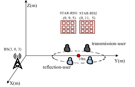
In this section, we present the numerical results to validate the performance of our proposed schemes. The investigated scenario is illustrated in Fig. 6, where reflection/transmission users are located on half-circles centered at (0m,10m,0m)0𝑚10𝑚0𝑚(0m,10m,0m) with a radius of 1m1𝑚1m. The main system parameters are shown in Table I. The BS is equipped with NRF=4subscript𝑁RF4N_{\rm RF}=4 RF chains to serve two reflection users and two transmission users. We assume that each RF chain is connected to KT=16subscript𝐾T16K_{\rm T}=16 TDs and each STAR-RIS composes NRIS=N1×N2=8×8subscript𝑁RISsubscript𝑁1subscript𝑁288N_{\rm{RIS}}=N_{1}\times N_{2}=8\times 8 elements.

Refer to caption
Fig. 6: The simulation scenario setup.
TABLE I: System parameters
Parameters Value
Central frequency fc=100subscript𝑓𝑐100f_{c}=100 GHz
Bandwidth B=10𝐵10B=10 GHz
Number of antennas Nt=128subscript𝑁𝑡128N_{t}=128
Number of subcarriers M=8𝑀8M=8
Number of TDs KT=16subscript𝐾T16K_{\rm{T}}=16
Number of STAR-RISs R=2𝑅2R=2
Number of STAR-RIS elements NRIS=64subscript𝑁RIS64N_{\rm{RIS}}=64
Number of users K=4𝐾4K=4
Number of RF chains NRF=4subscript𝑁RF4N_{\rm{RF}}=4
Maximum transmit power Pmax=15subscript𝑃max15P_{\rm{max}}=15 W
Noise power σm,k2=85superscriptsubscript𝜎𝑚𝑘285\sigma_{m,k}^{2}=-85 dBm

To show the convergency of 𝐀𝐥𝐠𝐨𝐫𝐢𝐭𝐡𝐦𝟏𝐀𝐥𝐠𝐨𝐫𝐢𝐭𝐡𝐦1\bf Algorithm\hskip 1.4457pt1, Fig. 7 plots the sum rate versus the number of iterations Iosubscript𝐼𝑜I_{o}, under four different structure schemes, including STAR-RIS with fully-connected structure, STAR-RIS with sub-connected structure, STAR-RIS with conventional structure, BS and STAR-RIS without TDs. For the STAR-RIS with sub-connected structure, we divide each STAR-RIS into S=2×2𝑆22S=2\times 2 sub-surfaces and each sub-surface consists of L=4×4𝐿44L=4\times 4 elements. We find that the sum rate speedily converges to stabilization with 12 iterations under all schemes, which shows the effectiveness of the proposed algorithm. Furthermore, the STAR-RIS with fully-connected structure owns the highest sum rate, while the sum rate under the BS and STAR-RIS without TDs is the lowest. However, the hardware complexity of the former is much higher than that of the latter. Therefore, to tradeoff the hardware complexity and system performance, the STAR-RIS with sub-connected structure is the best choice.

Refer to caption
Fig. 7: Sum rate versus the number of iterations Iosubscript𝐼𝑜I_{o}.
Refer to caption
Fig. 8: Sum rate versus the number of TDs.

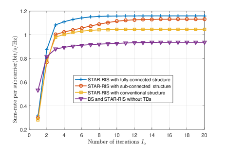
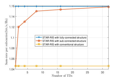
Fig. 8 provide the sum rate versus the number of TDs, i.e., the number of sub-surfaces S𝑆S. We can find that the sum rate under the STAR-RIS with sub-connected structure increases with the number of TDs S𝑆S grows up. It is noteworthy that small quantity of TDs can already obtain a good system performance. For example, it can reach more than 98%percent9898\% of the optimal sum rate when S16𝑆16S\geq 16. Meanwhile, its hardware complexity and power consumption is much lower than that of the STAR-RIS with fully-connected structure. It is obvious that the sum rate is the lowest for the STAR-RIS with conventional structure.

Refer to caption
Fig. 9: Sum rate versus bandwidth.

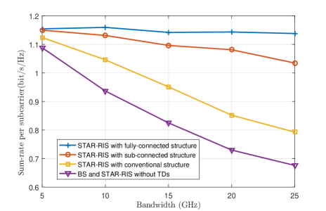
Then, Fig. 9 evaluates the sum rate versus bandwidth. The number of TDs is S=4𝑆4S=4 for each STAR-RIS with the sub-connected structure. It is well know that the beam split effect increases with the bandwidth. Therefore, for the BS and STAR-RIS without TDs structure, the sum rate speedily decreases with bandwidth increases. For the STAR-RIS with conventional structure, although STAR-RIS is not equipped with TDs, the BS still apply the TDs to mitigate partial beam split effect, and thus its sum rate is higher than that under the BS and STAR-RIS without TDs. Besides, since the number of TDs under the STAR-RIS with sub-connected structure is smaller than that of the STAR-RIS with fully-connected structure, its sum rate is a litter lower.

Refer to caption
Fig. 10: Sum rate versus the maximum transmit power.
Refer to caption
Fig. 11: Sum rate versus δ𝛿\delta.

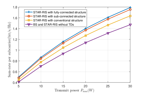
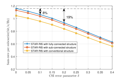
Fig. 10 plots the sum rate versus the maximum transmit power Pmaxsubscript𝑃maxP_{\rm max}. The number of TDs is S=4𝑆4S=4 for each STAR-RIS with the sub-connected structure. We can note that the sum rate grows up with Pmaxsubscript𝑃maxP_{\rm{max}} under different schemes. Particularly, the STAR-RIS with sub-connected structure still achieves very closed performance to the STAR-RIS with fully-connected structure. It demonstrates the effectiveness of the sub-connected structure, which can trade off the hardware cost and performance.

Additionally, in this paper, we provide the robustness of the joint beamforming against the impacts of imperfect CSI. The CSI uncertainties can be modeled as

~=+e,~Planck-constant-over-2-piPlanck-constant-over-2-pi𝑒\displaystyle\widetilde{\hbar}=\hbar+e, (62)

where ~~Planck-constant-over-2-pi\widetilde{\hbar} and Planck-constant-over-2-pi\hbar represent estimated and real channel, respectively, e𝑒e indicates the independent estimation error following complex Gaussian distribution with zero mean, i.e. e𝒞𝒩(0,σe2)similar-to𝑒𝒞𝒩0superscriptsubscript𝜎𝑒2e\sim\mathcal{C}\mathcal{N}\left(0,\sigma_{e}^{2}\right). We assume that the variance σe2superscriptsubscript𝜎𝑒2\sigma_{e}^{2} , i.e. the error power, satisfies σe2δ||2superscriptsubscript𝜎𝑒2𝛿superscriptPlanck-constant-over-2-pi2\sigma_{e}^{2}\triangleq\delta|\hbar|^{2} where δ𝛿\delta characterizes the level of CSI error.

Finally, the sum rate versus the CSI error parameter δ𝛿\delta is illustrated in Fig. 11. We can find that the performance loss grows with the increasing of δ𝛿\delta. The main reason is that the accuracy of the estimation angles deteriorates, which causes the beam misalignment. In particular, for the STAR-RIS with fully-connected structure, compared with the perfect CSI(i.e. δ=0𝛿0\delta=0), the system suffers a loss of 8%percent88\% with the error power δ=0.1𝛿0.1\delta=0.1, and a loss of 19%percent1919\% with δ=0.2𝛿0.2\delta=0.2. Besides, the STAR-RIS with sub-connected structure always outperforms the structure without TD and close to the STAR-RIS with fully-connected structure at any CSI error, which demonstrates the effectiveness and robustness of the proposed scheme.

VI Conclusions

In this paper, we investigated the STAR-RIS-assisted THz communication system and proposed two STAR-RIS structures to overcome the beam split effect. Meanwhile, we developed an joint optimization scheme of the hybrid analog/digital beamforming, time delays at the BS as well as the double-layer phase-shift coefficients, time delays and amplitude coefficients in a multiple STAR-RISs to maximize the system sum rate. Numerical results verified that the STAR-RIS with sub-connected structure can realize a better tradeoff the system performance and hardware cost. In future, we will investigate the practical phase shift model, and utilize the beam split effect to realize target sensing in the STAR-RIS-assisted wideband THz systems.

References

  • [1] B. Ning, Z. Tian, W. Mei, Z. Chen, C. Han, S. Li, J. Yuan, and R. Zhang, “Beamforming technologies for ultra-massive MIMO in terahertz communications,” IEEE Open J. Commun. Society, vol. 4, pp. 614-658, Feb. 2023.
  • [2] A. M. Elbir, K. V. Mishra, and S. Chatzinotas, “Terahertz-band joint ultra-massive MIMO radar-communications: model-based and model-free hybrid beamforming,” IEEE J. Sel. Topics Signal Process., vol. 15, no. 6, pp. 1468-1483, Nov. 2021.
  • [3] W. Hao, G. Sun, M. Zeng, Z. Chu, Z. Zheng, O. A. Dobre, and P. Xiao, “Robust design for intelligent reflecting surface assisted MIMO-OFDMA terahertz IoT networks,” IEEE Internet Things J., vol. 8, no. 16, pp. 13052-13064, Aug. 2021.
  • [4] B. Ning, Z. Chen, W. Chen, Y. Du, and J. Fang, “Terahertz multi-user massive MIMO with intelligent reflecting surface: beam training and hybrid beamforming,” IEEE Trans. Vehi. Technol., vol. 70, no. 2, pp. 1376-1393, Feb. 2021.
  • [5] H. Yuan, N. Yang, X. Ding, C. Han, K. Yang, and J. An, “Cluster-based multi-carrier hybrid beamforming for massive device Terahertz communications,” IEEE Trans. Commun., vol. 70, no. 5, pp. 3407-3420, May 2022.
  • [6] Q. Wu, S. Zhang, B. Zheng, C. You, and R. Zhang, “Intelligent reflecting surface aided wireless communications: a tutorial,” IEEE Trans. Commun., vol. 69, no. 5, pp. 3313-3351, May 2021.
  • [7] Q. Wu and R. Zhang, “Beamforming optimization for wireless network aided by intelligent reflecting surface with discrete phase shifts,” IEEE Trans. Commun., vol. 68, no. 3, pp. 1838-1851, Mar. 2020.
  • [8] X. Mu, Y. Liu, L. Guo, J. Lin, and R. Schober, “Simultaneously transmitting and reflecting (STAR) RIS aided wireless communications,” IEEE Trans. Wireless Commun., vol. 21, no. 5, pp. 3083-3098, May 2022.
  • [9] J. Xu, Y. Liu, X. Mu, R. Schober, and H. V. Poor, “STAR-RISs: A correlated T&\&R phase-shift model and practical phase-shift configuration strategies,” IEEE J. Sel. Topics Signal Process., vol. 16, no. 5, pp. 1097-1111, Aug. 2022.
  • [10] Y. Liu, X. Mu, R. Schober, and H. V. Poor, “Simultaneously transmitting and reflecting (STAR)-RISs: A coupled phase-shift model,” in Proc IEEE ICC 2022, Seoul, Korea, Republic of, May 2022, pp. 2840-2845.
  • [11] H. Niu and X. Liang, “Weighted sum-rate maximization for STAR-RISs-aided networks with coupled phase-shifters,” IEEE Systems J., vol. 17, no. 1, pp. 1083-1086, Mar. 2023.
  • [12] Y. Ma, M. Li, Y. Liu, Q. Wu, and Q. Liu, “Optimization for reflection and transmission dual-functional active RIS-assisted systems,” IEEE Trans. Commun., doi: 10.1109/TCOMM.2023.3286453.
  • [13] J. Tan and L. Dai, “Delay-phase precoding for THz massive MIMO with beam split,” in Proc IEEE GLOBECOM 2019, Dec. 2019, pp. 1-6.
  • [14] B. Ning, L. Li, W. Chen, and Z. Chen, “Wideband Terahertz communications with AoSA: beam split aggregation and multiplexing,” in Proc IEEE GLOBECOM 2022, Rio de Janeiro, Brazil, Dec. 2022, pp. 1709-1714.
  • [15] R. Zhang, W. Hao, G. Sun, and S. Yang, “Hybrid precoding design for wideband THz massive MIMO-OFDM systems with beam squint,” IEEE Systems J., vol. 15, no. 3, pp. 3925-3928, Sept. 2021.
  • [16] K. Spoof, V. Unnikrishnan, M. Zahra, K. Stadius, M. Kosunen, and J. Ryynanen, “True-time-delay beamforming receiver with RF resampling,” IEEE Trans. Circuits Syst. I, Reg. Papers, vol. 67, no. 12, pp. 4457-4469, Dec. 2020.
  • [17] L. Yan, C. Han, and J. Yuan, “Energy-efficient dynamic-subarray with fixed true-time-delay design for Terahertz wideband hybrid beamforming,” IEEE J. Sel. Areas Commun., vol. 40, no. 10, pp. 2840-2854, Oct. 2022.
  • [18] B. Zhai, A. Tang, C. Peng, and X. Wang, “SS-OFDMA: spatial-spread orthogonal frequency division multiple access for terahertz networks,” IEEE J. Sel. Areas Commun., vol. 39, no. 6, pp. 1678-1692, Jun. 2021.
  • [19] L. Dai, J. Tan, Z. Chen, and H. Vincent Poor, “Delay-phase precoding for wideband THz massive MIMO,” IEEE Trans. Wireless Commun., pp. 1-1, Mar. 2022.
  • [20] W. Hao, F. Zhou, M. Zeng, O. A. Dobre, and N. Al-Dhahir, “Ultra wide band THz IRS communications: applications, challenges, key techniques, and research opportunities,” IEEE Network, vol. 36, no. 6, pp. 214-220, Dec. 2022.
  • [21] W. Yan, W. Hao, C. Huang, G. Sun, O. Muta, H. Gacanin, and C. Yuen, “Beamforming analysis and design for wideband THz reconfigurable intelligent surface communications,” IEEE J. Sel. Areas Commun., vol. 41, no. 8, pp. 2306-2320, Aug. 2023.
  • [22] W. Hao, X. You, F. Zhou, Z. Chu, G. Sun, and P. Xiao, “The far-/near-field beam squint and solutions for THz intelligent reflecting surface communications,” IEEE Trans. Vehi. Technol., vol. 72, no. 8, 10107-10118, Sept. 2023.
  • [23] H. Sun, S. Zhang, J. Ma, and O. A. Dobre, “Time-delay unit based beam squint mitigation for RIS-aided communications,” IEEE Commun. Lett., vol. 26, no. 9, pp. 2220-2224, Sept. 2022.
  • [24] R. Su, L. Dai, and D. W. K. Ng, “Wideband precoding for RIS-aided THz communications,” IEEE Trans. Commun., vol. 71, no. 6, pp. 3592-3604, June 2023.
  • [25] H. Niu, Z. Chu, F. Zhou, P. Xiao, and N. Al-Dhahir, “Weighted sum rate optimization for STAR-RIS-assisted MIMO system,” IEEE Trans. Vehi. Technol., vol. 71, no. 2, pp. 2122-2127, Feb. 2022.
  • [26] Z. Wang, X. Mu, J. Xu, and Y. Liu, “Simultaneously transmitting and reflecting surface (STARS) for Terahertz communications,” IEEE J. Sel. Topics Signal Process., doi: 10.1109/JSTSP.2023.3279621.
  • [27] B. Zheng, C. You, and R. Zhang, “Intelligent reflecting surface assisted multi-user OFDMA: Channel estimation and training design,” IEEE Trans. Wireless Commun., vol. 19, no. 12, pp. 8315-8329, Dec. 2020.
  • [28] S. Ma, W. Shen, J. An, and L. Hanzo, “Wideband channel estimation for IRS-aided systems in the face of beam squint,” IEEE Trans. Wireless Commun., vol. 20, no. 10, pp. 6240-6253, Oct. 2021
  • [29] H. Li, M. Li, Q. Liu, and A. L. Swindlehurst, “Dynamic hybrid beamforming with low-resolution PSs for wideband mmWave MIMO-OFDM systems,” IEEE J. Sel. Areas Commun., vol. 38, no. 9, pp. 2168-2181, Sept. 2020.
  • [30] C. Han and I. F. Akyildiz, “Distance-aware bandwidth-adaptive resource allocation for wireless systems in the terahertz band,” IEEE Trans. THz Sci. Technol., vol. 6, no. 4, pp. 541-553, Jul. 2016.
  • [31] X. Wei, D. Shen, and L. Dai, “Channel estimation for RIS assisted wireless communications-part II: an improved solution based on double-structured sparsity,” IEEE Commun. Lett., vol. 25, no. 5, pp. 1403-1407, May 2021.
  • [32] J. An, C. Xu, D. W. K. Ng, C. Yuen, L. Gan, and L. Hanzo, “Reconfigurable intelligent surface-enhanced OFDM communications via delay adjustable metasurface,” arXiv preprint arXiv:2110.09291, Oct. 2021.
  • [33] O. E. Ayach, S. Rajagopal, S. Abu-Surra, Z. Pi, and R. W. Heath, “Spatially sparse precoding in millimeter wave MIMO systems,” IEEE Trans. Wireless Commun., vol. 13, no. 3, pp. 1499-1513, Mar. 2014.
  • [34] J. Tan and L. Dai, “Wideband beam tracking in THz massive MIMO systems,” IEEE J. Sel. Areas Commun., vol. 39, no. 6, pp. 1693-1710, June 2021.
  • [35] K. Shen and W. Yu, “Fractional programming for communication systems part II: uplink scheduling via matching,” IEEE Trans. Signal Process., vol. 66, no. 10, pp. 2631-2644, May 2018.
  • [36] Q. Zhu, M. Li, R. Liu, Y. Liu, and Q. Liu, “Joint beamforming designs for active reconfigurable intelligent surface: a sub-connected array architecture,” IEEE Trans. Commun., vol. 70, no. 11, pp. 7628-7643, Nov. 2022.
  • [37] M. Grant and S. Boyd, “CVX: MATLAB software for disciplined convex programming,” 2016. [Online]. Available: http://cvxr.com/cvx
  • [38] S. Boyd, N. Parikh, E. Chu, B. Peleato, and J. Eckstein, “Distributed optimization and statistical learning via the alternating direction method of multipliers,” Nov. 2014, [Online] Available: https://stanford.edu/boyd/papers/pdf/admm distr stats.pdf.