Viscoelastic increase of detachment stress of a rigid punch from adhesive soft viscoelastic layers
Abstract
The problem of the detachment of a sufficiently large flat indenter from a plane adhesive viscoelastic strip of thickness “b” is studied. For any given retraction speed, three different detachment regimes are found: (i) for very small “b” the detachment stress is constant and equal to the theoretical strength of the interface, (ii) for intermediate values of “b” the detachment stress decays approximately as b-1/2, (iii) for thick layers a constant detachment stress is obtained corresponding to case the punch is detaching from a halfplane. By using the boundary element method a comprehensive numerical study is performed which assumes a linear viscoelastic material with a single relaxation time and a Lennard-Jones force-separation law. Pull-off stress is found to consistently and monotonically increase with unloading rate, but to be almost insensitive to the history of the contact. Due to viscoelasticity, unloading at high enough retraction velocity may allow punches of macroscopic size to reach the theoretical strength of the interface. Finally, a corrective term in Greenwood or Persson theories considering finite size effects is proposed. Theoretical and numerical results are found in very good agreement.
keywords:
Viscoelasticity , Crack propagation , Thin layer , Detachment force.[inst1]organization=Department of Mechanics, Mathematics and Management, Politecnico di Bari,addressline=via Orabona 4, city=Bari, postcode=70125, country=Italy
[inst2]organization=Department of Mechanical Engineering, Hamburg University of Technology,addressline=Am Schwarzenberg-Campus 1, city=Hamburg, postcode=21073, country=Germany
1 Introduction
Soft materials are of great interest in the scientific community as for their applicability in many engineering fields ranging from the automotive sector [1], biomechanics [2], soft robotics [3, 4], manipulators [5], tires grip[1], sealing of syringes[6], finger-touch-pad interactions [7, 8], soft tissue adhesion for regenerative medicine [9, 10]and pressure-sensitive adhesives [11]. With soft polymers macroscopic adhesion due to van der Waals adhesive interactions remains strong [12], whereas in hard materials it is easily canceled by the inevitable surface roughness.
In many of these applications the bond strength is a crucial mechanical property and it is often quantified by measuring the apparent adhesion strength as given by the maximum pulling force per unit area in a tensile bond test [13]. Peng et al. [13] have already elucidated how the critical pull-off force of a flat rigid axisymmetric punch adhered to an elastic film of finite thickness depends by two dimensionless parameters. The former shows a transition from uniform detachment (DMT-like) to crack-like propagation (JKR-like), while the latter is a correction factor due to finite thickness of the film.
However, in many of the applications mentioned above, soft materials (polymers, elastomers) are employed, which are known to be viscoelastic, i.e. they exhibit a frequency-dependent modulus and dissipation [14], and this complicates their mechanical adhesive behaviour. Numerous experiments in steady state conditions have shown that the apparent surface energy , i.e. the energy per unit area needed to separate two ideally parallel surfaces, during the crack opening is related to the crack speed through a power law function [15, 16, 17, 18], commonly referred as the Gent and Schulz empirical law [19]
| (1) |
where is the adiabatic surface energy (or thermodynamic work of adhesion), is the crack velocity, and are constants with and is the WLF factor to translate viscoelastic modulus results at various temperatures [20]. In its simplest form Gent and Schulz empirical law Eq. (1) is generally a good phenomenological model for opening cracks, while for closing cracks a reduced apparent surface energy is observed which generally shows the reciprocal of that law [21, 22, 23, 24, 25, 26]. There is no indication in the law of a limit enhancement, nor it is clear how far it can be used for transient conditions. Finally, and most importantly, in this empirical law, there is no indication on possible size effects, i.e. on how the parameters of the law should be affected by geometry, and which instead we shall find is not always true, even for advancing crack.
There are two main approaches which have been attempted to capture more fundamentally the propagation of viscoelastic crack propagation. One is based on the description of the processes occurring at the crack tip through a cohesive zone model [27, 25, 26, 28], and as such is rather general as it can take into account of initiation of the crack, transient propagation, and steady state. Also it may show a transition to a cohesive rupture for small enough cracks (what Peng et al. [13] call uniform DMT-like detachment in their case, see also [29, 30, 31]), in principle it may be generalized to rate-dependent cohesive laws, and to non linear materials. In practice, it attempts to model the real processes occurring at the crack tip. The other, developed by Persson and coauthors [22, 23, 24], takes an “energy-based” approach and is restricted to linear materials and to steady state conditions. It is derived by equating the power input in the system with the power dissipated by viscoelastic losses and by the rate at which energy is spent to create new surfaces. The energy-based approach finds different results for finite size systems where it seems to show non-monotonic and also [23], which is in contrast to the limit case of cohesive failure where can decrease down to zero for very small crack (see [29]), as we shall discuss in details here with respect to our geometry. Only for a semi-infinite system and linear material both approaches yield a very similar monotonically increasing behavior of with respect to up to the theoretical “high-frequency” limit of , where and respectively represent the glassy (high frequency) and the rubbery (low frequency) modulus of the viscoelastic material [32]111In their basic form, both approaches consider to be an intrinsic material property and therefore rate-independent, as we shall also assume here. . Furthermore, the cohesive model has been applied modelling of bi-materials crack (one elastic, one viscoelastic) [33] showing transient dissipation can be arbitrarily large while loads remain finite and hence dissipation should not be taken as an indication of true fracture energy [34].
Recently, it has been shown that, depending on the indenter geometry, the loading history may or may not affect the detachment force. For a Hertzian indenter, Afferrante and Violano [30, 31] have shown that the loading velocity and the maximum indentation reached during the loading phase can significantly influence the pull-off force. One the other hand, Papangelo and Ciavarella [29] found that when considering an axisymmetric flat punch, the loading history has a relatively weak effect, and the primary determinant of the pull-off force is largely the unloading velocity. This is partly related to the fact that, for a given preload, the contact area achieved at maximum indentation strongly depends on the loading history only for a Hertzian indenter, while it remains fixed for a flat punch. This interpretation is somehow confirmed by the recent work of Muller et al. [35] which further considers the contact of a flat punch indenter with superimposed small scale roughness. Their study focuses on the significant hysteresis that is observed during crack closure and opening which is obtained by the concurrent presence of viscoelasticity and adhesion. They find that small scale roughness can indeed leads to loacal jumps -in and -out of contact, which causes the dependence of the detachment force on the preload.
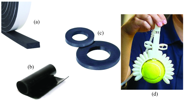
While previous works have focused on the detachment from viscoelastic semi-infinite substrates [29, 36, 37], the influence of the layer thickness on the detachment process has been mostly overlooked. Nevertheless, the latter has a broad interest in engineering applications where often a thin layer of viscoelastic material is used, as in Figure 1, as well as to exploit the thin layer testing geometries, like in Peng et al. [13] which could permit to extract cohesive properties as well as surface energy properties.
Hence, in the present study, we focus on the detachment problem of a flat punch indenting a thin adhesive viscoelastic layer of finite thickness in plane strain conditions. The remainder of the paper is organized as follows. In Section 2 the elastic solution for halfplane contact is recalled. In Section 3, the case of a thin layer is considered leveraging on the the “thin strip” assumption by Johnson [38] and applying the Griffith energy balance. This serves to determine the limiting solutions within which the viscoelastic results should be confined. In Section 4 the numerical scheme is introduced which is based on the boundary element method and it assumes a standard linear model for the viscoelastic layer and a Lennard-Jones force-separation law for the contact interactions, which is rate-independent. In Section 5 the numerical results are presented and compared with Greenwood theory for viscoelastic crack propagation [21] which we extend for finite size effects. In Section 6 the conclusions are drawn. The study is carried on with particular emphasis on the effect of (i) the loading history, (ii) the layer thickness and (iii) the unloading velocity on the pull-off force and on the effective adhesive energy.
2 Detachment from a halfplane
Let us consider the plane contact problem of a flat punch of semi-width indenting an elastic adhesive frictionless halfplane with Young modulus and Poisson ratio . By applying the Griffith energy balance, the pull-off force [39, 40] is given by
| (2) |
where is the layer width, is the plane strain elastic modulus. Hence the mean interfacial stress at pull-off is
| (3) |
which has the classical Linear Elastic Fracture Mechanics (LEFM) square-root dependence with respect to the punch semiwidth . Overbar indicates here the mean value. This implies that smaller punches have a higher pull-off stress, potentially reaching the theoretical strength (or the cohesive strength) of the interface, denoted as . This is typically observed for punches with a semi-width less than the following typical fracture length
| (4) |
In what follows in the paper we shall assume that the punch size is as we are interested in the transitions due to the finite size of the layer rather than the size of the punch. For the latter effect the reader is referred to Ref. [29].
Hence, in dimensionless form, we have the following relations
| (5) |
| (6) |
where we have assumed a Lennard-Jones force-separation law, for which , where is the range of interaction and is a constant, , is usually in the range of for soft polymers [41, 42, 40], implying to be 1 to 10 times higher than the range of attractive forces. For a true crystal, this would imply a range of few nanometers, but for soft materials, the range of adhesive forces may be larger. If a viscoelastic material with relaxed modulus and instantaneous modulus is considered, then in the limit of very slow and very fast unloading rate we will have
| (7) |
where and .
3 Detachment from a thin layer
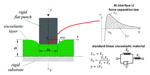
If the substrate has a finite thickness, it is necessary to consider the effect of thickness in the analysis. Hence, here we focus on the plane contact problem of a flat punch with a semi-width of indenting an adhesive layer with a thickness of (Fig. 2). We first focus on the linear elastic solution, and then we will provide the limiting solutions for the viscoelastic problem based on the elastic formulation.
3.1 Elastic layer
Let us consider the layer in plane strain and supported by a rigid foundation. In the following the case of frictionless contact between the layer and the rigid substrate is considered while the correction due to the Poisson effect for the case of a layer perfectly bonded to the substrate is shown in the Appendix-I.
Following Johnson [38], we assume that plane sections remain plane upon loading. Hence for the case of no friction between the layer and the rigid substrate, the load and the corresponding elastic strain energy stored in the layer are
| (8) | ||||
| (9) |
where is the indentation considered positive when the flat punch is approaching the substrate, consequently, is positive when tensile. At unloading, the Griffith energy balance requires the elastic strain energy released per unit area to be equal to the surface energy. Hence, assuming detachment occurs immediately, we have the following relations
| (10) |
where, and are the indentation and the average interfacial stress at pull-off respectively. Notice that the pull-off stress depends on the layer thickness as , hence it is possible to define a characteristic thickness of the substrate where reaches the theoretical interfacial strength , i.e.
| (11) |
which is of the same order of magnitude of . Experiments with PDMS elastomers in Peng et al. [13], show that this is of the order of mm, where clearly their loading rate corresponds to a certain effective elastic modulus. On the other hand, in the limit of a very thick layer, we should obtain the half-plane solution, for which we can utilize Eq. (3) and Eq. (10) to determine a length scale
| (12) |
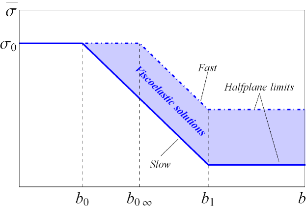
with the meaning that for substrates thicker than one should anticipate the half-plane behaviour. Notice that, while is a characteristic lengthscale that depends on the material and interfacial properties, depends on the punch semi-width. Overall as indicated by Eq. (11) and Eq. (12), and as illustrated in Fig 3, we identify the following three regimes
| (13) |
or, in dimensionless form,
| (14) |
3.2 Limiting solutions for a viscoelastic layer
Let us assume that the layer is constituted by a viscoelastic material with relaxed Young modulus and instantaneous Young modulus so that . In the limit of very slow/very fast unloading rate the substrate behaves as elastic. Thus, for the case of no friction between the substrate and the layer, according to Eq. (10), one can anticipate the following two scenarios
| (15) |
or in dimensionless form
| (16) |
where, one should notice that for rapid unloading (very fast scenario) the pull-off stress will reach the cohesive strength by the following value of the substrate thickness:
| (17) |
However, for a thick layer, the halfplane limit will be always obtained at irrespective of the unloading rate. Figure 3 schematically displays the elastic limits at low and high retraction speed that constitute the bounds for the possible viscoelastic solutions.
Form Eq.s (12) and (17) it follows that if then . In other words, if at a high enough retraction velocity, it is possible to reach the adhesive strength of the interface. It is easy to find elastomers with [43]. This implies that punches with semiwidth much larger than can still reach the theoretical interfacial strength if unloading is performed fast enough. Also, this holds for layer thickness. If we assume that the experiments with PDMS in Peng et al. [13] were conducted relatively slowly, when was of the order of mm, then clearly could reach very large values, provided the punch is also large enough. This peculiarity may be exploited in the future as a technique to improve/enhance interfacial adhesion in micro-structured interfaces by optimizing not only the micro-pillar geometry, but also the unloading protocols.
4 Numerical implementation of the adhesive viscoelastic contact problem
In this section, the numerical scheme used to solve the adhesive viscoelastic contact problem is introduced. We utilized the boundary element method, which necessitates the discretization solely of the interface. A similar code has been used in previous works for solving both adhesive elastic [44] and viscoelastic [29] axisymmetric contact problems, therefore, in this section, we will focus on the essential adaptations required to tailor the implementation for a plane viscoelastic strip.
The flat punch interacts with the viscoelastic layer according to the Lennard-Jones 3-9 force-separation law defined as
| (18) |
where is the traction ( when it is tensile), is the interfacial gap and is the equilibrium distance. The theoretical strength of the interface (maximum tensile stress) is then equal to and takes place at a separation equal to . The gap is a function of the in-plane coordinate as
| (19) |
where, is the deflection of the viscoelastic layer with respect to the origin ( is positive as shown in Fig. 2). Here, Eq. (19) is solved numerically in a discrete manner at the nodes, being the number of equally spaced elements with the length of . Following Bentall and Johnson [45] we implemented the method of overlapping triangles, i.e. for the -th node the pressure is 0 at node , rises linearly to at node and then falls linearly to 0 at node , which gives overall a linear variation of the contact pressure over the considered domain. With respect to the case of constant pressure elements, a picewise-linear distribution of normal tractions produces a displacement field which is everywhere smooth and continuous. Hence, according to Bentall and Johnson [45] the vertical deflection at node of an elastic layer relatively to the origin due to a triangular distribution of pressure centered in is
| (20) |
where are integers numbers, is the pressure acting on the -th node determined using Eq. 18 ( when it is tensile), , and , , are the following integral functions222Care should be taken when integrating which converges slowly. The Appendix 3 of Bentall and Johnson [45] suggests a convenient integration strategy we have also adopted. Notice that Bentall and Johnson [45] contains a misprint as the second part in which is split up should be integrated over the interval .
| (21) | ||||
| (22) | ||||
| (23) |
By applying the superposition principle, the normal deflection at node due to a piecewise linear distribution of pressure can be written as
| (24) |
where each column of the compliance matrix corresponds to the displacement field due to a unity triangular pressure centered at node being all the other nodes unloaded. Therefore, the displacement field and, correspondingly, the compliance matrix can be readily computed using Eq. (20). Once the elastic solution is obtained, the displacement field of the viscoelastic layer , can be determined by the elastic-viscoelastic correspondence principle in the form of Boltzmann integrals [46] as
| (25) |
where is the dimensionless creep compliance function, the strain variation after an application of a constant unit stress, and, in our discrete formulation, the Green function is replaced by the appropriate tensor , so that the viscoelastic nodal displacements at time are
| (26) |
where the symbol “” stands for the row by column product. For the linear viscoelastic material, the standard model is assumed with a single relaxation time , composed by a spring placed in series with an element constituted by a dashpot and a spring in parallel (see Fig. 2), for which the dimensionless creep compliance function is as follows
| (27) |
5 Results
Here the results of the numerical investigations are shown by using the following dimensionless parameters
| (28) |
and is the (dimensionless) average stress at pull-off and is defined as . If not stated differently, in our simulations we considered , , and .
5.1 History dependence
Viscoelastic materials typically exhibit a “history-dependent” response and this tremendously affects the detachment force in Hertzian indenters [30, 31]. Hence, first we aimed to explore how different loading scenarios affect the detachment characteristics of the flat indenter we considered, while keeping the unloading rate constant. The simulations were carried out under displacement control using a trapezoidal function (see inset in Fig. 4.a) which main parameters are shown in Table 1. We define the dwell time as , the unloading rate , and the loading rate as with reference to the the inset of Figure 4.a. We endeavored to investigate the impact of different loading protocols meticulously although the unloading curves presented in Figure 4 are restricted to the six different protocols described in Table 1.
| Loading protocol | |||||
|---|---|---|---|---|---|
| # 1 | 1 | 1 | very fast | 10 | 0 |
| # 2 | 1 | 1 | very slow | 10 | 0 |
| # 3 | 0 | 1 | 5 | 10 | 0 |
| # 4 | 2 | 2 | very fast | 10 | 0 |
| # 5 | 2 | 2 | very slow | 10 | 0 |
| # 6 | 0 | 2 | 5 | 10 | 0 |
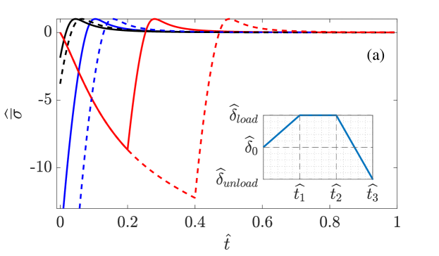
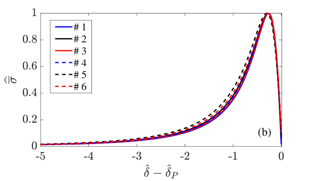
These loading scenarios included: (i) Unloading from a fully relaxed substrate after a slow loading process, indicated by the black curves (2,5). (ii) Unloading following rapid loading, causing the substrate to exhibit an elastic response with , as denoted by the blue curves (1,4). (iii) Unloading after indenting the substrate at a constant loading rate , represented by the red curves (3,6). It’s important to note that while the loading phase is not shown for curves (1, 2, 4, 5), we accounted for the pre-loading effect in our simulations. Furthermore, the maximum indentation depth was kept at for curves (1, 2, 3) (solid lines) and set to for curves [4, 5, 6] (dashed lines). The punch has , and the viscoelastic layer’s (dimensionless) thickness is which is equivalent to .
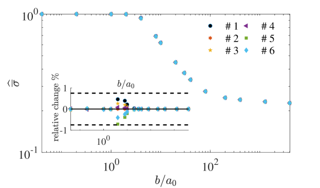
The primary result from Fig. 4 is that, regardless of the significant variations in loading conditions, the magnitude of the pull-off stress remains consistent across various loading histories. Indeed, one can conclude that the pull-off stress remains nearly unaffected by the loading history. In Figure 4.b, we present the same curves as in Fig. 4.a, but with a shift in the horizontal axis by . This shift corresponds to the indentation depth at which the normal load vanishes during unloading. It helps to better observe the slight changes in the unloading trajectories. Furthermore a comprehensive investigation on the effect of the different loading scenario was conducted for various layer thicknesses. In Figure 5, we illustrate versus the variation in thickness . The legend in Figure 5 clarifies that the plot presents results derived from all the loading conditions in Table 1, all with the same unloading rate. Remarkably, these plots closely overlap, indicating very similar values across the various simulations for all the thicknesses tested. To further quantify the distinctions between these loading cases, we examined the relative changes in pull-off stress with respect to one specific case that serves as the foundation for our subsequent investigations. The results are plotted in the inset of Figure 5 as a relative change for various thickness values. It’s evident that within a certain accuracy we can state that the detachment force of a flat indenter from a viscoelastic adhesive strip is negligibly influenced by the loading history of the contact. For the remainder of the paper we will consider unloading the viscoelastic strip from a fully relaxed condition, unless explicitly stated otherwise, we assume , .
5.2 Dependence on the unloading rate
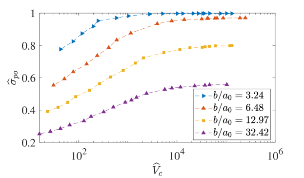
After establishing that the loading history does not influence the pull-off stress , we examine how varies with respect to the layer thickness for four different unloading rates: represented in Fig. 6 by black diamonds, green circles, red squares, and pink triangles, respectively. Figure 6 shows a comprehensive analyses for the punch semi-width . The results are obtained starting from a fully relaxed substrate. For , we reach the cohesive limit, where the pull-off stress remains independent on both the unloading rate and the layer thickness, approaching the theoretical value . Most importantly, for , the curves align well with the LEFM (Linear Elastic Fracture Mechanics) solution we have derived in Section 3 showing a scaling of . Here, the pull-off stress increases with the unloading rate, and the pull-off data consistently stay well by the “slow” and “fast” limits we derived, represented by the blue dashed and solid black lines, respectively. For a thickness larger than the curves align with the half-plane solution and, for a given unloading rate, the pull-off stress remains constant independently on the layer thickness.
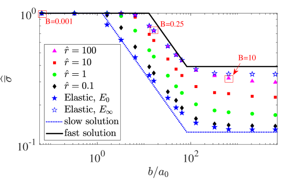
Notice that in the theoretical elastic solution the detachment happens with no propagation (, being the semi-width of the crack ligament). Clearly, this condition is never achieved in a more refined cohesive zone model, as it is the one we have implemented numerically. This accounts for the small deviations we found in the limiting case of very fast and very slow unloading between numerical and theoretical results. Nevertheless, to ascertain the correctness of the numerical viscoelastic results, the plots also include the curves obtained unloading an elastic strip with modulus (filled blue stars) and (empty blue stars). One easily recognizes that the viscoelastic solutions are perfectly bounded between the two limiting elastic cases.
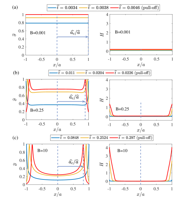
To support our conclusion we focus on the mechanism of crack propagation and stress distribution at the interface from the unloading onset up to pull-off. Figures 7 show the stress distribution for three specific cases out of the 120 cases shown in Fig. 6. All the cases are for unloading rate . The punch radius in Figure 7 is . The corresponding points for these three cases are highlighted with red squares in Fig. 6. According to Fig. 7, during unloading, the crack propagates at the interface hence the semi-width of the crack ligament is smaller than the punch semi-width when pull-off happens. This explains the difference between the expected pull-off stress from the analytical limits and the actual pull-off stress.
Figure 7 displays three distinct cases with different values of (0.001, 0.25, and 10), denoted as Figures 7a, 7b, and 7c, respectively. Figure 7a pertains to the cohesive zone, where the detachment occurs at and with a uniform distribution of tensile tractions at the interface. For a more comprehensive understanding of crack propagation and the detachment process, we have included gap plots on the right side of Figure 7. These plots represent the gap between the rigid punch and the viscoelastic layer as a function of the in plane coordinate . Figure 7a illustrates that in the cohesive region the gap is uniformly distributed at the interface, with no crack formation. This is, in fact, the reason why we can achieve numerically with the same results as the expected analytical results (see Figure 6 for ). In contrast, for the other two cases, as depicted in Figures 7b and 7c, we observe crack propagation, with detachment occurring at . Notably, for larger values of , a reduction in the ratio is evident, resulting in the small deviation observed in Fig. 6 between the numerical and the analytical results.
A more detailed view on the dependence of the pull-off stress on rate effects is shown in Fig. 8 that shows as a function of the crack speed at pull-off, defined as
| (29) |
where represents the crack ligament semi-width, which decreases as the crack propagates at the interface. The results are closely related to the interaction between adhesion and viscoelastic dissipation in the strip (see also [33]), indeed it represents one of the major objective of viscoelastic crack propagation theories [27, 25, 26, 28, 22, 23, 24]. Consequently, we conducted additional analyses to examine this effect. We selected four different cases with a punch radius of and the corresponding thickness ratios of , corresponding to the blue, orange, yellow, and purple curves, respectively. We conducted numerical experiments with 20 different unloading rates ranging from to to obtain curves representing a wide range of the dimensionless crack velocity at pull-off.
The analysis of Fig. 8 illustrates clearly the trend: thin layers and high retraction velocity favour high pull-off stress. Nevertheless, this effect is mitigated when the as, in the cohesive region, the detachment tends to happen at a uniform stress.
Although, the pull-off force reduces increasing the layer thickness the enhancement in terms of effective surface energy remains the same when moving from low to high unloading rates, provided that . Based on the thin layer elastic solution Eq. (10) we define the effective surface energy as
| (30) |
where we considered that in general the detachment happens at . Hence, in dimensionless form,
| (31) |
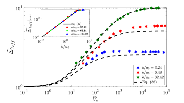
Fig. 9 shows that the normalized effective surface energy increases monotonically with respect to the crack velocity at pull-off up to a certain plateau value. In the case of , the normalized effective surface energy reaches its theoretical upper limit (all our simulations are for k=0.1). Notice that for any thickness of the layer larger than one would get the maximum possible enhancement . Care should be taken when interpreting the data using Eq. 31 as, if the latter is used for this may lead to unrealistic enhancements , which is due to the fact that for the halfplane solution should be considered.
It’s important to note that, due to the finite size effect, for cases with , we observe the maximum enhancement of the normalized effective surface energy to be lower than . This happens because, for the very thin layer, the cohesive region is approached, namely the DMT-type failure rather than the JKR-type, in the Peng et al. [13] terminology. In the latter case, if we assume , and , and with the acquisition of Eq. (6), one can obtain the following relation for the maximum enhancement that can be reached at high retraction rates
| (32) |
which turns out to be solely dependent on the ratio . In order to validate our upper bound enhancement factor (Eq. (32)), we considered three distinct values of punch semi-width , on fully relaxed viscoelastic substrate with varying ratios, unloaded at a high unloading rate . The inset of Fig. 9 shows that the maximum enhancement obtained numerically compared very well with Eq. (32).
We incorporated this correction in Greenwood (2004) theory [21] for crack propagation in viscoelastic semi-infinite media, which, in its original form gives
| (33) |
where
| (34) | ||||
| (35) |
Equation (33) for very slow propagation gives , while at high speed provides the maximum enhancement . This picture, on which all present theories agree, is valid for semi-infinite solids, nevertheless, in agreement with recent results [30, 31, 29], we have found that due to finite size effects the maximum enhancement may be consistently reduced. For the present problem, if , the maximum enhancement will be given by , so we propose here a generalization of Eq. (33) for
| (36) |
where we have explicitly indicated that now the velocity dependent effective surface energy depends not only on the crack speed, but also on the ratio between the layer thickness and the fracture length . Notice that for Eq. (33) remains valid, while for the effective energy is velocity independent and equal to . Figure 9 compares the predictions obtained with the finite size Greenwood model (Eq. (36)) against the numerical results, which are found in fairly good agreement. This result (Eq. (32)), obtained with the more general cohesive-based theory, could also be used to correct the theory of Persson-Brener (2005) [22] and Persson (2017) [23], as we shall do in Appendix-II.
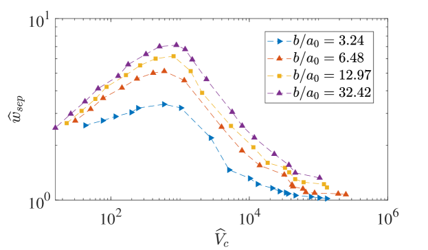
One important parameter to examine is the work of separation, which is defined as
| (37) |
which indicates the energy spent during the unloading phase to separate the contact. We calculated this parameter for four different layer thicknesses, specifically , which corresponds to the blue, orange, yellow, and purple curves in Fig. 10. Similarly to previous research works [30, 31, 29] the has a typical bell shape; at low and high velocity there is little energy expenditure to separate the contact as the material behaves essentially as elastic, but for intermediate regimes presents a maximum related to the dissipative phenomena happening in the viscoelastic layer.
6 Conclusions
The plane problem of the detachment of a large flat punch from an adhesive viscoelastic layer of finite thickness has been studied. First, we have derived an elastic model based on the “thin strip” assumption by Johnson [38]. It was found that the pull-off stress decays as . Nevertheless, this functional dependence is bounded (i) for very thin layer by the cohesive limit where the pull-off stress equals the theoretical stress of the material, (ii) for very thick layer by the halfplane limiting solution. The elastic model provided the bounds for the viscoelastic analysis. We found that if the layer is thin, particularly at high enough retraction velocity, the theoretical limit of the material could be reached. This turns particularly interesting as for soft polymers may easily be of the order of and this amplifies the layer thickness for which the theoretical strength can be observed. Clearly, this behavior will be hindered by the fact that during unloading the crack starts to propagate at the interface hence, at pull-off, the actual crack ligament is smaller than the punch semi-width.
Theoretical predictions have been compared with boundary element numerical simulations for a standard linear viscoelastic material and using a Lennard-Jones force-interaction law. We have shown that the loading conditions have a negligible effect on the pull-off force, in contrast with what was shown for a Hertzian geometry. Instead, the pull-off force consistently increases with the unloading rate up to a certain plateau given by the cohesive strength of the interface.
Finally, we have shown that when the data are represented in terms of effective surface energy, at high velocity the theoretical enhancement given by is reached only when the layer thickness is larger than a characteristic lengthscale . For the maximum adhesion enhancement is limited by finite size effect and in particular we found . Hence, we have proposed an extension of Greenwood and Persson crack propagation theories accounting for finite size effects which we found in good agreement with numerical results.
7 Funding
A.P. and A.M. were supported by the European Union (ERC-2021-STG, “Towards Future Interfaces With Tuneable Adhesion By Dynamic Excitation” - SURFACE, Project ID: 101039198, Grant No. CUP: D95F22000430006). Views and opinions expressed are however those of the authors only and do not necessarily reflect those of the European Union or the European Research Council. Neither the European Union nor the granting authority can be held responsible for them. A.P. was partially supported by Regione Puglia (Italy), project ENOVIM (Grant No. CUP: D95F21000910002) granted within the call “Progetti di ricerca scientifica innovativi di elevato standard internazionale” (art. 22 della legge regionale 30 novembre 2019, n. 52 approvata con A.D. n. 89 of 10-02-2021, BURP n. 25 del 18-02-2021). All the authors acknowledge support by the Italian Ministry of University and Research (MUR) under the programme “Department of Excellence” Legge 232/2016 (Grant No. CUP—D93C23000100001).
Appendices
Appendix-I. Perfectly bonded layer
For the case of a layer perfectly bonded to the rigid substrate, following Johnson [38], we only need to correct the previous results for the Poisson effect with (this requires , [38]), so that we have
| (38) |
where equals the cohesive strength of the material for the layer thickness
| (39) |
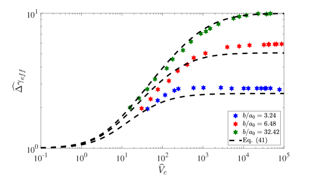
Appendix-II. An extension of Persson and Brener viscoelastic crack propagation theory accounting for finite size effects
Using Persson and Brener theory [22] for a single relaxation time material gives an implicit equation for the effective adhesion energy [32]
| (40) |
being . Eq. (40) can be extended to finite size systems by accounting that for a very thin layer the maximum enhancement will be reduced to , so we propose here a generalization of Eq. (40) in order to take into account finite size systems, i.e. for
| (41) |
where we have explicitly indicated that the normalized effective surface energy depends not only on the crack speed, but also on the ratio between the layer thickness and the fracture length . A comparison between the numerical results and Eq. (41) is shown in Fig. 11.
References
- [1] B. Lorenz, Y. R. Oh, S. K. Nam, S. H. Jeon, B. N. J. Persson, Rubber friction on road surfaces: Experiment and theory for low sliding speeds, The Journal of Chemical Physics 142 (19) (2015).
- [2] B. Mazzolai, A. Mondini, F. Tramacere, G. Riccomi, A. Sadeghi, G. Giordano, S. Carminati, Octopus-inspired soft arm with suction cups for enhanced grasping tasks in confined environments, Advanced Intelligent Systems 1 (6) (2019) 1900041.
- [3] G. Giordano, M. Carlotti, B. Mazzolai, A perspective on cephalopods mimicry and bioinspired technologies toward proprioceptive autonomous soft robots, Advanced Materials Technologies 6 (12) (2021) 2100437.
- [4] G. Giordano, M. Gagliardi, Y. Huan, M. Carlotti, A. Mariani, A. Menciassi, B. Mazzolai, Toward mechanochromic soft material-based visual feedback for electronics-free surgical effectors, Advanced Science 8 (15) (2021) 2100418.
- [5] J. Shintake, V. Cacucciolo, D. Floreano, H. Shea, Soft robotic grippers, Advanced Materials 30 (29) (2018) 1707035.
- [6] C. Huon, A. Tiwari, C. Rotella, P. Mangiagalli, B. N. J. Persson, Air, helium and water leakage in rubber o-ring seals with application to syringes, Tribology Letters 70 (2) (2022) 35.
- [7] F. Forsbach, M. Heß, A. Papangelo, A two-scale fem-bam approach for fingerpad friction under electroadhesion, Frontiers in Mechanical Engineering 8 (2023) 1074393.
- [8] L. Felicetti, C. Sutter, E. Chatelet, A. Latour, L. Mouchnino, F. Massi, Tactile discrimination of real and simulated isotropic textures by friction-induced vibrations, Tribology International 184 (2023) 108443.
- [9] S. A. Burke, M. Ritter-Jones, B. P. Lee, P. B. Messersmith, Thermal gelation and tissue adhesion of biomimetic hydrogels, Biomedical materials 2 (4) (2007) 203.
- [10] B. M. Gumbiner, Cell adhesion: the molecular basis of tissue architecture and morphogenesis, Cell 84 (3) (1996) 345–357.
- [11] A. Asbeck, S. Dastoor, A. Parness, L. Fullerton, N. Esparza, D. Soto, M. Cutkosky, Climbing rough vertical surfaces with hierarchical directional adhesion (2009) 2675–2680.
- [12] C. A. Dahlquist, Pressure-sensitive adhesives (1969) 219–260.
- [13] B. Peng, X.-Q. Feng, Q. Li, Decohesion of a rigid flat punch from an elastic layer of finite thickness, Journal of the Mechanics and Physics of Solids 139 (2020) 103937.
- [14] R. Christensen, Theory of viscoelasticity: an introduction, Elsevier, 2012.
- [15] C. Creton, M. Ciccotti, Fracture and adhesion of soft materials: a review, Reports on Progress in Physics 79 (4) (2016) 046601.
- [16] M. Barquins, D. Maugis, Tackiness of elastomers, The Journal of Adhesion 13 (1) (1981) 53–65.
- [17] A. N. Gent, Adhesion and strength of viscoelastic solids. is there a relationship between adhesion and bulk properties?, Langmuir 12 (19) (1996) 4492–4496.
- [18] A. N. Gent, R. P. Petrich, Adhesion of viscoelastic materials to rigid substrates, Proceedings of the Royal Society of London. A. Mathematical and Physical Sciences 310 (1502) (1969) 433–448.
- [19] A. N. Gent, J. Schultz, Effect of wetting liquids on the strength of adhesion of viscoelastic material, Journal of Adhesion 3 (4) (1972) 281–294.
- [20] M. L. Williams, R. F. Landel, J. D. Ferry, The temperature dependence of relaxation mechanisms in amorphous polymers and other glass-forming liquids, Journal of the American Chemical Society 77 (1955) 3701–3707.
- [21] J. Greenwood, The theory of viscoelastic crack propagation and healing, Journal of Physics D: Applied Physics 37 (18) (2004) 2557.
- [22] B. N. J. Persson, E. A. Brener, Crack propagation in viscoelastic solids, Physical Review E 71 (3) (2005) 036123.
- [23] B. N. J. Persson, Crack propagation in finite-sized viscoelastic solids with application to adhesion, EPL (Europhysics Letters) 119 (1) (2017) 18002.
- [24] B. N. J. Persson, A simple model for viscoelastic crack propagation, The European Physical Journal E 44 (2021) 1–10.
- [25] R. A. Schapery, A theory of crack initiation and growth in viscoelastic media, Int. J. Fracture 11 (1975) 141–159.
- [26] R. A. Schapery, A theory of crack initiation and growth in viscoelastic media ii. approximate methods of analysis, Int. J. Fracture 11 (3) (1975) 369–388.
- [27] G. J. A, J. K. L, The mechanics of adhesion of viscoelastic solids, Phil. Mag. A 43 (1981) 697–711.
- [28] R. Schapery, A theory of viscoelastic crack growth: revisited, International Journal of Fracture 233 (2022) 1–16. doi:10.1007/s10704-021-00605-z.
- [29] A. Papangelo, M. Ciavarella, Detachment of a rigid flat punch from a viscoelastic material, Tribology Letters 71 (2) (2023) 48.
- [30] L. Afferrante, G. Violano, On the effective surface energy in viscoelastic hertzian contacts, Journal of the Mechanics and Physics of Solids 158 (2022) 104669.
- [31] G. Violano, L. Afferrante, On the long and short-range adhesive interactions in viscoelastic contacts, Tribology Letters 70 (3) (2022) 1–5.
- [32] M. Ciavarella, G. Cricrì, R. McMeeking, A comparison of crack propagation theories in viscoelastic materials, Theoretical and Applied Fracture Mechanics 116 (2021) 103113.
- [33] M. Ciavarella, A. Papangelo, R. McMeeking, Crack propagation at the interface between viscoelastic and elastic materials, Engineering Fracture Mechanics 257 (2021) 108009.
- [34] M. Ciavarella, A. Papangelo, R. M. McMeeking, Transient and steady state viscoelastic crack propagation in a double cantilever beam specimen, International journal of mechanical sciences 229 (2022).
- [35] C. Müller, M. Samri, R. Hensel, E. Arzt, M. H. Müser, Revealing the coaction of viscous and multistability hysteresis in an adhesive, nominally flat punch: A combined numerical and experimental study, Journal of the Mechanics and Physics of Solids 174 (2023) 105260.
- [36] L. Afferrante, G. Violano, G. Carbone, Exploring the dynamics of viscoelastic adhesion in rough line contacts, Scientific Reports 13 (1) (2023) 15060.
- [37] F. Forsbach, A simple semi-analytical method for solving axisymmetric contact problems involving bonded and unbonded layers of arbitrary thickness, Machines 11 (4) (2023) 474.
- [38] K. L. Johnson, Contact Mechanics, Cambridge University Press, New York, 1985.
- [39] J. R. Barber, Contact Mechanics, Springer International Publishing, Berlin, 2018.
- [40] D. Maugis, Contact, adhesion and rupture of elastic solids, Vol. 130, Springer Science & Business Media, Heidelberg, 2000.
- [41] A. Jagota, S. J. Bennison, C. A. Smith, Int. j. fracture 104, 105–130 (2000), International Journal of Fracture 104 (2000) 105–130.
- [42] T. Tang, A. Jagota, M. K. Chaudhury, C. Y. Hui, Thermal fluctuations limit the adhesive strength of compliant solids, The Journal of Adhesion 82 (7) (2006) 671–696.
- [43] A. Bonfanti, J. L. Kaplan, G. Charras, A. Kabla, Fractional viscoelastic models for power-law materials, Soft Matter 16 (26) (2020) 6002–6020.
- [44] A. Papangelo, M. Ciavarella, A numerical study on roughness-induced adhesion enhancement in a sphere with an axisymmetric sinusoidal waviness using lennard-jones interaction law, Lubricants 8 (9) (2020) 90.
- [45] R. H. Bentall, K. L. Johnson, An elastic strip in plane rolling contact, International Journal of Mechanical Sciences 10 (8) (1968) 637–663.
- [46] R. Christensen, Theory of viscoelasticity: an introduction, Elsevier, New York, 2012.