Development of a Whole-body Work Imitation Learning System
by a Biped and Bi-armed Humanoid
Abstract
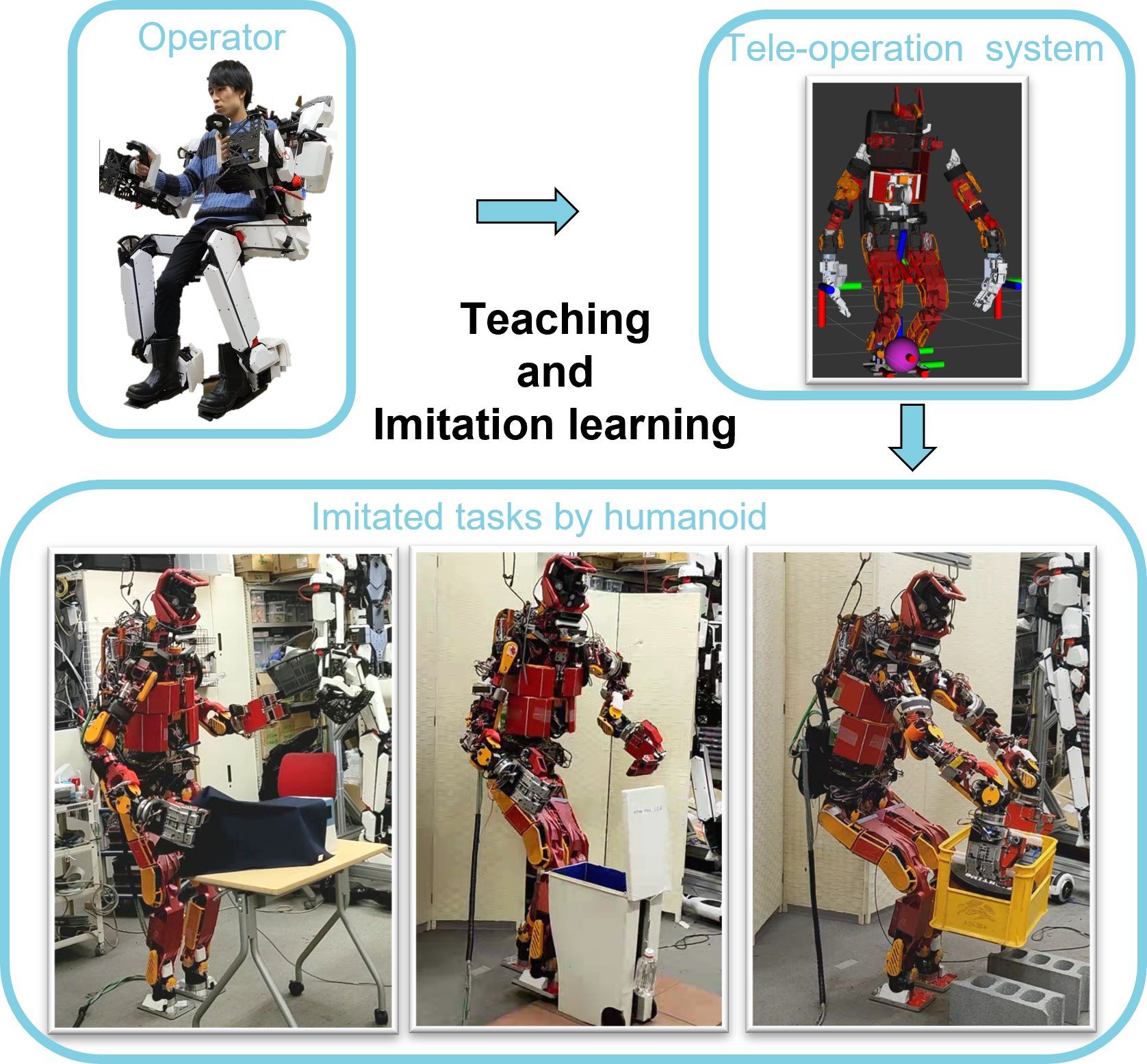
Imitation learning has been actively studied in recent years. In particular, skill acquisition by a robot with a fixed body, whose root link position and posture and camera angle of view do not change, has been realized in many cases. On the other hand, imitation of the behavior of robots with floating links, such as humanoid robots, is still a difficult task. In this study, we develop an imitation learning system using a biped robot with a floating link. There are two main problems in developing such a system. The first is a teleoperation device for humanoids, and the second is a control system that can withstand heavy workloads and long-term data collection. For the first point, we use the whole body control device TABLIS. It can control not only the arms but also the legs and can perform bilateral control with the robot. By connecting this TABLIS with the high-power humanoid robot JAXON, we construct a control system for imitation learning. For the second point, we will build a system that can collect long-term data based on posture optimization, and can simultaneously move the robot’s limbs. We combine high-cycle posture generation with posture optimization methods, including whole-body joint torque minimization and contact force optimization. We designed an integrated system with the above two features to achieve various tasks through imitation learning. Finally, we demonstrate the effectiveness of this system by experiments of manipulating flexible fabrics such that not only the hands but also the head and waist move simultaneously, manipulating objects using legs characteristic of humanoids, and lifting heavy objects that require large forces.
I INTRODUCTION
In the field of teleoperation, there is also limited research on the manipulation of heavy objects. For instance, even in the research by Ishiguro [1], manipulation was limited to short periods. There are even fewer examples of learning for heavy object manipulation. Therefore, in this study, we combine low-cycle posture generation, which includes whole-body joint torque minimization for high-load work and long-term data collection, with high-cycle posture generation, which focuses on the constraints for tasks that require tracking the operator’s command posture. While there exists an optimization method [2] that generates a sequence of key poses considering the manipulated objects, this study focuses on data collection for imitation learning and implements an optimization calculation with a narrowed number of constraints for remote piloting.
Using a system for a humanoid robot with the above two features, we collect data and realize various motions by imitation learning[3]. We will demonstrate the effectiveness of this system through experiments of manipulation of a flexible cloth, which requires simultaneous movement of the head and waist as well as the hands, manipulation of a trash can using the legs characteristic of humanoids, and manipulation of a heavy object that requires a large force to move the hands, waist, and knees at the same time.
In recent years, imitation learning has been extensively studied and the acquisition of diverse movements became possible. In particular, various skill acquisitions have been accomplished by dual-armed robots [4, 5]. In these studies, the body is fixed, and there is no change in the pose of the robot’s root links or the camera angle during operation. Conversely, research on floating-link robots such as humanoid robots remains a challenging task with few studies[6]. Therefore, this study aims to develop an imitation learning system for floating-link bipedal robots. There are two main problems in developing such a system for a biped humanoid robot with bipedal locomotion.
The First is the development of a control device capable of operating humanoid robots. The second is a robust control system that can withstand long-term data collection in floating-link systems. For the first issue, typically, robots are controlled using VR devices, 3D mice, GUI, and so on. Some studies have utilized dynamic neural network models to learn the object manipulation behavior of small humanoid robots and reproduce appropriate movements according to the environment [7]. Other studies have automatically created models that consider multiple modalities by directly instructing small humanoid robots [8]. However, this direct teaching of actions can be non-intuitive and only achievable in robots with high back drivability. Although simple movements can be replicated using motion-capture-based remote control [9], this approach is not adaptable for tasks that require contact force control with the environment due to the lack of haptic feedback to the operator. Approaches to achieving tasks such as folding cloth have been proposed [10], but these do not consider using humanoid-specific legs or camera angle variations. Therefore, in this study, we utilize the TABLIS device developed by Ishiguro [1]. This device is a cockpit-like exoskeleton control device that can control both arms and legs and achieve bilateral control with a task-executing robot. We connect this TABLIS with the humanoid robot JAXON [11] to construct a control system capable of collecting data for imitation learning.
For the second issue, we will build a system that can operate heavy objects and collect long-term data based on optimization of torque and contact force, and still be able to move not only the robot’s limbs but also the head and waist. simultaneously. Research has been conducted on mimicking human movements that include balance constraints such as standing on one leg [12], as well as cloning human dual-arm work based on the learning of essential movements and optimization of movements such as avoiding collision through observation of human works [13]. However, there are some learning issues, and the robot does not manipulate the environment, or only imitates dual-arm tasks for a short period.
II SYSTEM IN THIS STUDY
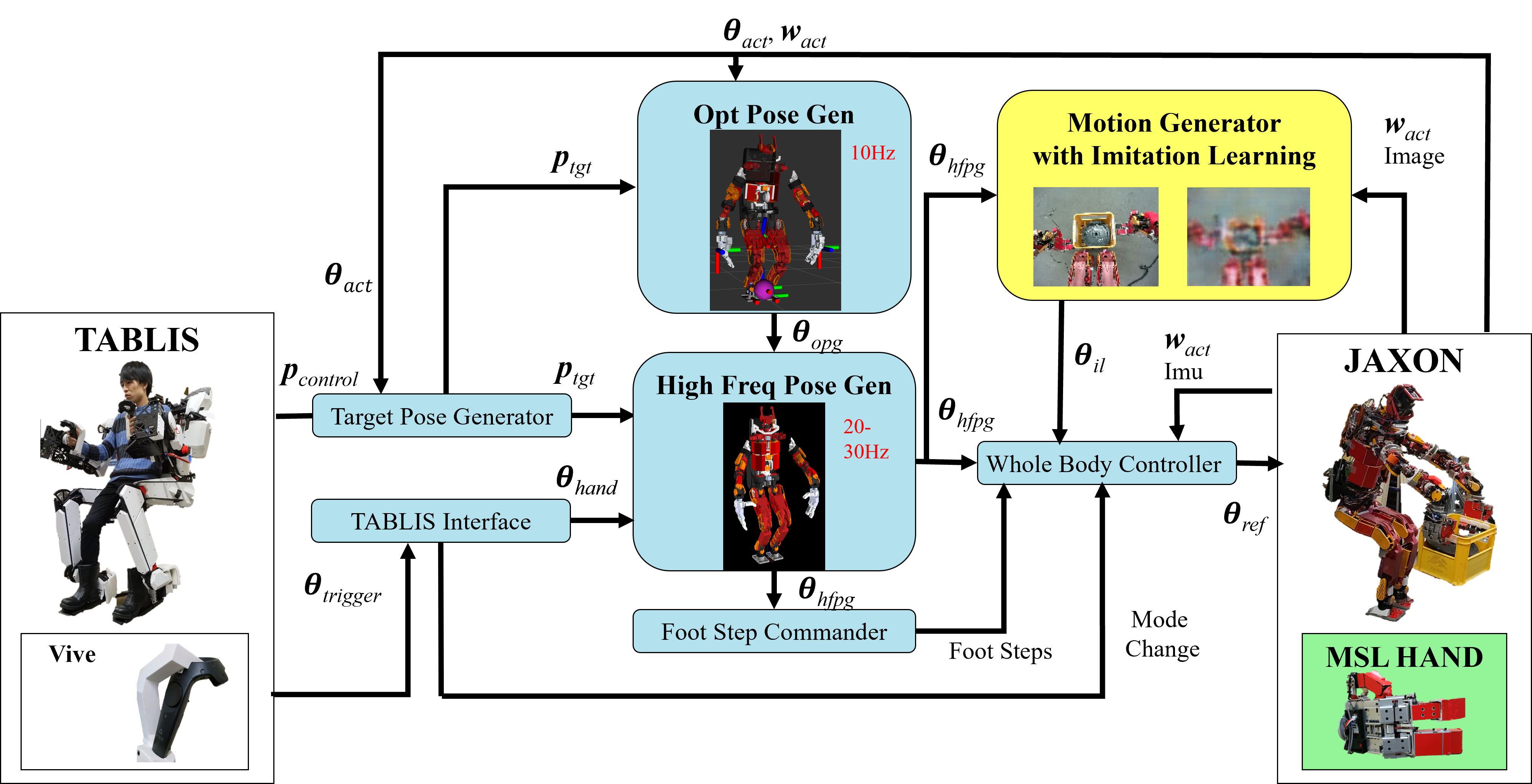
A diagram of the entire system from the operator and the control device TABLIS to the real robot JAXON is shown in Fig.2. The overall system consists of two major components.
The first is a teleoperation system for work teaching including TABLIS. It takes as input the operator’s hand and foot positions and posture obtained from TABLIS and the trigger values of the hand controller. It generates JAXON’s whole body joint angle sequences through two posture generators, OPG (Opt Pose Gen) and HFPG (High Freq Pose Gen). We will explain in detail how TABLIS works, the overall data flow, the posture feedback correction in the Whole Body Controller (WBC), the hand controller triggers, and the use of button inputs in Sec. III. The details of the posture generation method, including torque minimization, which contributes to long-term behavior, are described in Sec. IV.
The second is a system of imitation learning. The learning is performed using the output angle sequence from the HFPG in the teleoperation system and the sensor values from the actual robot. After acquiring a model, the target joint angle sequence for the next step is sent to the actual robot based on the robot status and sensor values during work execution. The specific application of this method to humanoids will be described in Sec. V.
In this study, we conducted experiments with a life-size humanoid JAXON equipped with a highly durable hand, MSL HAND [14]. This hand has three fingers and five degrees of freedom, and the angles of two fingers can be geometrically fixed. This allows the hand to withstand loads of 1000 N or more with one hand. This locking function was also used in an experiment to lift a heavy box. In addition to the high output whole body joints, the durability of the hand, which is the point of contact with the environment, was also increased to achieve a hardware configuration that enables data collection over long periods.
III Humanoid Teleoperation System for Whole-body Work Teaching
III-A Configuration and data flow of teleoperation system
We describe the configuration of a teleoperation system for teaching. First, the hand and foot positions and posture obtained from TABLIS are input to the Target Pose Generator (SubSec. III-C) and output as the target position posture . The two whole-body pose generators, described in Sec. IV, receive this and generate a sequence of whole-body angles. The final is sent to WBC (SubSec. III-F), which modifies it based on the wrench and joint information of the actual robot, mainly considering balance, and gives it to the actual robot. When performing foot manipulation, is also sent to Foot Step Commander (SubSec. III-E), where switching control of the contact state based on the difference in foot height is performed. Finger angle command and button input for teaching are controlled by TABLIS Interface (SubSec. III-D).
III-B Whole body control device TABLIS
TABLIS is a boarding-type full-body exoskeleton cockpit for humanoids and has 7-DOFs for each arm, 1-DOF for the trunk, and 6-DOFs for each leg, totaling 27-DOFs. In this research, we used the acquisition of 6-DOFs of position and posture of the four end-effectors in the operator’s hands and feet, and the feedback of force sensor values of the real robot. We mounted a controller with five buttons and one trigger on the TABLIS hand tip. The trigger is used to maneuver the hand, and the buttons serve to switch modes, etc.
III-C Target Pose Generator
Target Pose Generator takes as input the 6-dimensional positional posture of the limbs obtained from TABLIS and outputs the target positional posture for the actual whole body posture generation. This system uses the relative displacement from the start of the maneuver to perform the maneuver. At the start of maneuvering, and the position posture of JAXON’s limbs are acquired and saved as initial values. After the start, the target positional posture is calculated by multiplying the relative difference from the operator’s initial positional posture by a constant value that reflects the difference in proportions between TABLIS and JAXON. The scale of the robot’s movement can be tuned by this constant value. In addition, the target position and posture can be output according to the task, such as fixing the target value of a specific link by command from the Tablis Interface or rotating the target posture for easy maneuvering.
III-D TABLIS Interface
Based on the trigger and button inputs obtained from the hand controllers, Tablis Interface controls the hand and mode switching for work teaching. We show the inputs from the controller and functions in Table.I, where Lb-1 indicates left-hand button 1 and Rt-1 indicates right-hand trigger input. Note that L/R denotes left and right hand, and b/t denotes button and trigger. We send a command to HFPG and stop sending commands to the robot. When resuming work we send commands to HFPG,OPG,HFPG to resume command sending with the initial values of TABLIS and JAXON’s posture at that time. For finger maneuvering, the one-dimensional value of the trigger is converted to the joint angles of the three fingers (index, middle, and thumb) and integrated with the sequence of joint angles other than the fingers at HFPG. The start and end commands for data collection are also controlled by this node.
| button or trigger name | function |
|---|---|
| Lb-1 | pause control |
| Lb-2 + Lb-3 | reset robot pose |
| Lt-1 | control left finger angle |
| Rb-1 | restart control |
| Rb-2 + Rb-3 | send record trigger |
| Rt-1 | control right finger angle |
III-E Foot Step Commander
Foot Step Commander is a component for changing the foot contact state. It obtains the angle sequence from HFPG and calculates the foot posture. It sets a threshold value for the difference between the heights of the two feet and switches to the free foot mode if the difference is greater than the threshold value. The following is performed here.
-
•
It changes the target link for the contact force constraint of OPG to one foot or both feet.
-
•
It changes the target link for the force balancing task of OPG.
-
•
It Specifies the target foot position from that of the generated posture and send it to WBC.
The third function sends the positions of both feet in the generated posture to WBC at first, and then controls the foot transition between one-leg standing and both-leg standing in WBC, taking balance into consideration.
III-F Whole Body Controller
The following is performed with , imu values, force sensor values, and joint encoder values from the robot as inputs.
-
•
It updates the target exerted force of the hand tip based on the sensor values.
-
•
It overwrites the center of gravity position based on the exerted force and current foot position.
-
•
It fixes the target position of the link in contact with the environment.
-
•
It calculates the target exerted force of the foot and output the target joint torque.
WBC adds together the target joint torque obtained from the joint angle obtained above, the target joint torque obtained from the target exerted force, and the gravity compensation torque, and converts them into a current value to generate a command to the motor. For the foot switching command from Foot Step Commander, the current position posture of the foot and the received target position posture are used to generate a trajectory that takes the transition of the center of gravity into account and controls the foot movement.
IV Whole-body pose generation with torque minimization for long time data collection
IV-A Integration of two posture generators with different control cycles
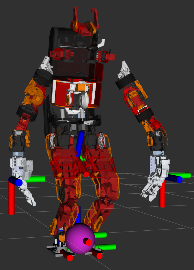
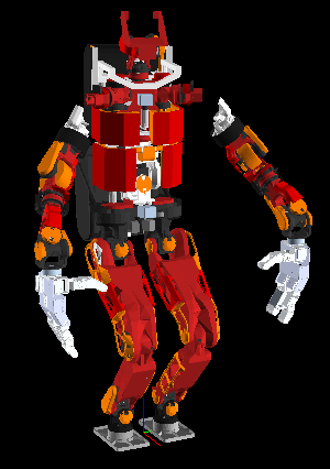
By integrating two stages of pose calculation, low-cycle optimized pose generation and constraint-focused high-cycle pose generation, we aimed to achieve both whole-body torque minimization and maneuverability. Both of them receive the target positional posture of the limbs in Target Pose Generator and generate the whole-body joint angles. First, the joint angles are computed in OPG, taking into account multiple tasks and constraints (Fig.3(a)). The cycles are approximately 5 to 10 hz. Based on this angle sequence, a forward kinematics calculation of the upper body using the target positional posture of the hand tip is performed at about 30 Hz by Fig.3(b), and the angles are slightly modified (Fig.3(b)). This corresponds to tasks such as manipulation, which require fine manipulation of the hand tip. The details of these two pose generators are explained in the following sections.
IV-B Whole body posture generation including torque optimization (OPG)
This section describes in detail how to generate postures by optimization calculations, taking into account the torque, force balance, collision avoidance, and other constraints. An example of the generated posture is shown in Fig.3(a). The coordinates of each limb are the target position posture of the end-effector. The pink sphere near the feet is the calculated center of gravity of the robot. The coordinates near the root link represent the target posture of the root link. The position is not considered for this link.
IV-B1 Formulation as an inverse kinematics optimization problem considering statics
First, we describe the optimization method. Let be the configuration to be designed. and are the dimensions of the configuration and task, respectively. The robot motion generation problem is defined as obtaining a task function satisfying .
| (1) |
Since Eq.1 is a nonlinear equation, it is difficult to find a solution analytically. Therefore, we generally consider an optimization problem such as Eq.2 and find the optimal configuration of Eq.1 by performing iterative calculations using numerical methods.
| (2a) | |||
| (2b) | |||
We express this as more general linear equality and linear inequality constraints as follows. We generate the robot posture by analytically solving this equation as a constrained nonlinear optimization problem using sequential quadratic programming.
| (4) | |||||
IV-B2 Design variables
The search variable consists of the joint angle and the contact wrench . Here, is the joint angle of the whole body plus 6 dimensions of the position and posture of the root link. Also, is a vector of forces and moments for each link in contact with the environment. is the number of whole body joints and is the number of contact force targets.
| (5) |
-
Joint angles [rad] [m]
-
Contact wrench [N] [Nm]
IV-B3 Objective function
The objective function of the optimization calculation is defined as follows. Here we considered the kinematic goal, the force-moment balance, the whole-body torque balance, and the center-of-gravity position goal as objective functions to be satisfied. The denotes the number of kinematic constraints.
| (6) |
-
Kinematic task [rad] [m]
-
Wrench task [N] [Nm]
-
Torque task [Nm]
-
COM position task [m]
IV-B4 Kinematic objective function
The denotes the error between the target position-posture and the current position-posture of the link of interest. is the mth target position, is the current position of the mth objective link, is the mth target posture matrix and is the current posture matrix of the mth objective link. is a function to extract the angular axis vector of the rotation matrix .
is the one-dimensional weight of each target link, where is the Adamar product. By setting different weight values for each link, it is possible to determine which link has a smaller error. We considered the positional posture of the limbs as the kinematic goal in this study and gave the posture of the root link and the head link according to tasks. For the root link and head link, we add a small weight for the posture only.
IV-B5 Balance of forces and moments
For simplicity was replaced by the error function of the force in Eq.9 and the moment error function in Eq.10.
| (9) | |||||
| (10) | |||||
is the target exerted force at the mth objective link, is the target exerted moment, is the robot weight [kg], is the gravitational acceleration [m/s/s], is the mth target position, is the current position of the robot root link, is the current position of the robot’s center of gravity.
IV-B6 Balance of whole body joint torque
The equation for the balance between the drive torque and the required torque is shown in Eq.11.
| (11) |
is the target joint torque, is the self-weight torque by gravity, and is the torque by contact force. By adopting a 0 vector as , we can optimize the whole body exerted torque as close to 0 as possible.
IV-B7 Center of gravity objective function
The equation for the center-of-gravity position target is shown in Eq.12.
| (12) |
corresponds to the target position of the center of gravity and to the current center of gravity position. We can set weights for this target task as well as others, and smaller weights have the role of improving the symmetry of posture and exerted force.
IV-C Constraints
As constraints, we considered the following. We can set weights for each of them, and by adjusting the relative magnitude of the weights, we can adjust the importance of each constraint and change the posture.
IV-C1 Upper and lower limits of joint angle
The constraint equation for the joint upper and lower limits is shown in Eq.13.
| (13) |
The upper and lower limits () are set considering the upper and lower limits of hardware and the angle margin for balance control.
IV-C2 Upper and lower limits of joint torque
The constraint equation for the joint torque upper and lower limits is shown in Eq.14.
| (14) |
The motor ratcheting torque with a margin is set as . It is possible to suppress tooth skipping of harmonic gears.
IV-C3 Collision avoidance constraints
The collision avoidance constraint equation is shown in Eq.15.
| (15) |
We set the constraint to make the distance between the two specified links greater than the margin. is the margin and , are the positions of the nearest neighbor points of the two links.
IV-C4 Height of root link constraints
The constraint equation for the height of the root link is shown in Eq.16.
| (16) |
is the z value of the root link position and is the height offset. and are the z values of both hand positions. The values of both weights are important because they are basically in conflict with the torque optimization task. In this case, the height of both hands was used as the criterion for lowering the center of gravity since the maneuver was performed using the positional posture of both hands.
IV-C5 Foot contact force constraints
The constraint equation for the foot contact force is shown in Eq.17.
| (17) |
is a 12-row matrix, which includes the conditions that the forces in the x- and y-axis of the sole should be within the static friction force, that the force in the z-direction should be positive, and that the center of gravity should be within the specified range. is the orientation matrix to the end-effector, which is transposed and multiplied by from the left to transform the coordinate of the target wrench.
IV-C6 End-effector exertion force constraints
Constraints for generating a posture that satisfies the desired exerted force at end effectors are shown in Eq.18.
| (18) |
denotes the target exerted wrench of the limb. You can set weights for each value of the 6-axis wrench for each link. By adjusting each weight, the link to be considered can be changed.
IV-D High frequency pose generation (HFPG)
HFPG modifies the joint angles based on the inverse kinematics of the upper body using the positional posture of both limbs obtained from Target Pose Generator and the whole body joint angle sequence from OPG. HFPG ensures maneuverability in situations such as manipulation tasks, which require detailed maneuvering of hands. The target joints include the joints of the trunk and both arms, but not the legs. Calculations are performed at a period of about 30 Hz, depending on each task. An example of the generated posture is shown in Fig.3(b).
V Imitation learning for humanoid robots
The proposed system is used for work teaching, and the skills are acquired through imitation learning [3].
V-A Overview of imitation learning methods
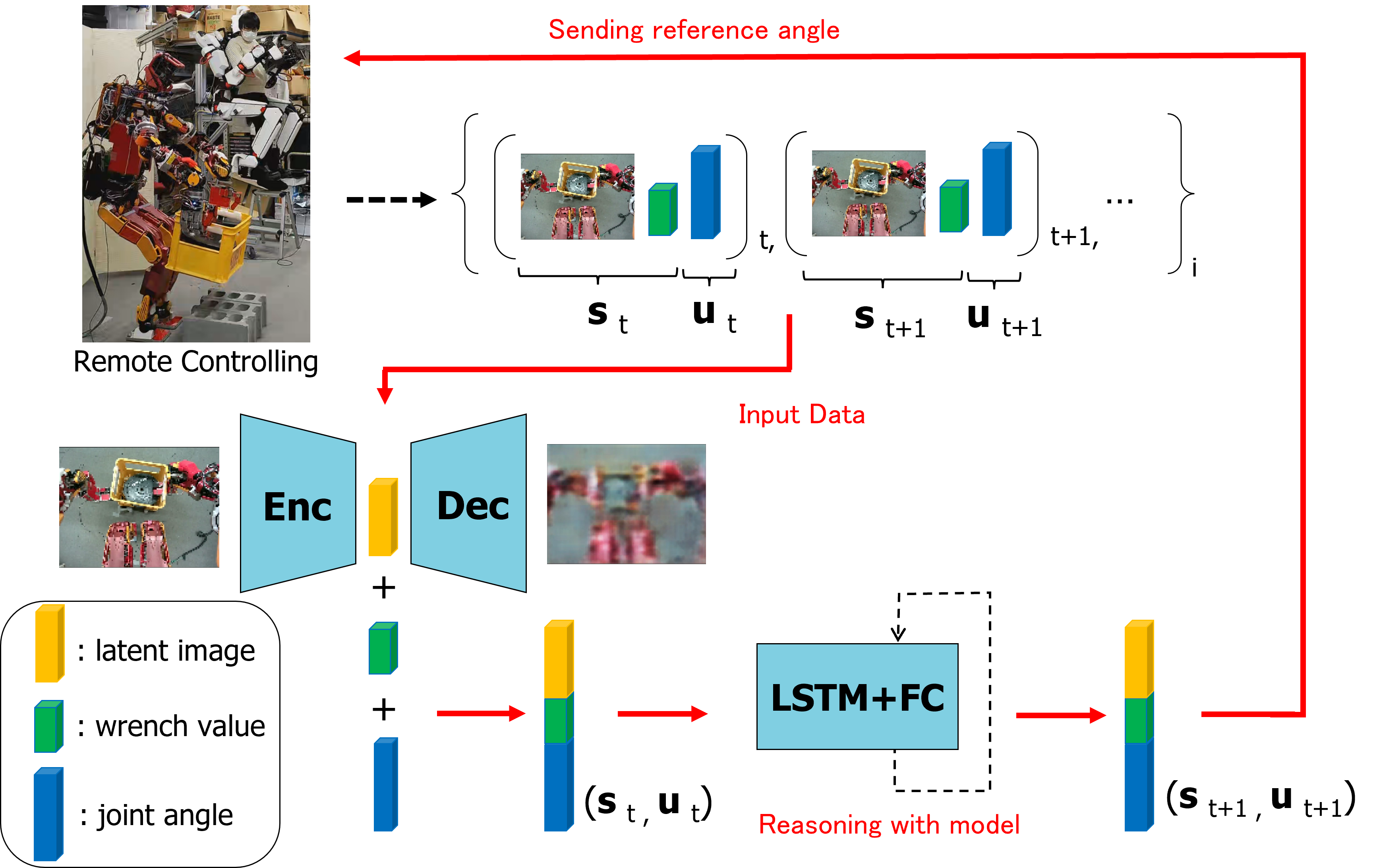
The basic formula for learning is shown in Eq.19. We also show the overall system in Fig.4. Here represents the current time step, the sensory state of the robot, the control input to the robot, the parametric bias, and the prediction model including the network weight . In this study, is the camera images and force sensor values of the robot, and is the joint angle sequences of the whole body. It is a recursive network with 10 layers in total, 4 of which are the Fully Connected (FC) layer, 2 of which are the Long Short Term Memory (LSTM) layers[15], and 4 of which are FC layers. The activation function is Hyperbolic Tangent and the optimizer is Adam [16]. The and are normalized values and a two-dimensional parametric bias is used.
| (19) |
V-B Teaching and Learning
First, we collect and time sequence data. In this study, we collect data by teaching using the system proposed in Sec. III. Data are collected through multiple task realizations in which the target environment is changed. The pairs of time sequence data in each trial are defined as (, K is the number of total trials, is the number of motion steps in each trial). The images are pre-trained using Auto Encoder [17] for dimensionality reduction and feature extraction. 128x96 RGB images were compressed into a 12-dimensional vector and used for training. We use these vectors with parametric bias as training data. The is a value for each dynamic, in which the operator’s movement style is embedded. The model is trained using this data, and is updated along with the network weight . The initial value of is set to 0 and the loss function is the mean squared error.
VI Experiments on imitation of whole-body tasks
In this chapter, we describe work teaching experiments using the proposed humanoid robot maneuvering system considering whole-body torque and skill acquisition experiments using imitation learning. Three types of tasks were performed: manipulating a flexible cloth, maneuvering legs characteristic of humanoids, and lifting a heavy object requiring center-of-gravity movement. We present the results and discussion of each experiment.
VI-A Experiments of flexible cloth manipulation
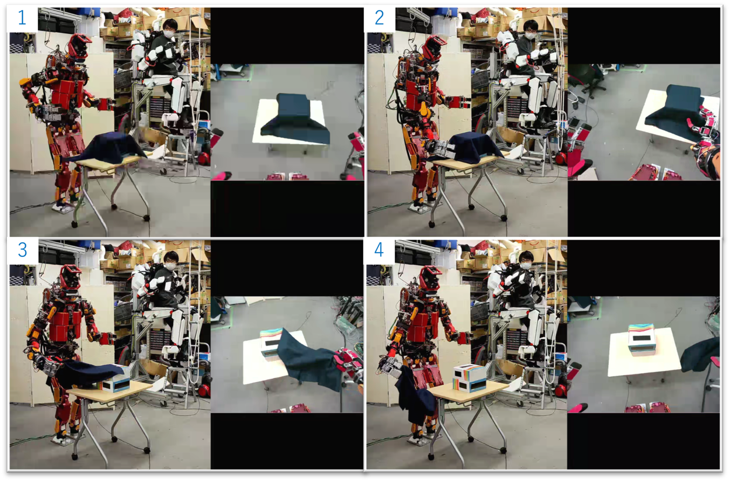
JAXON removing the flexible cloth by maneuvering with TABLIS is shown in Fig.5. The left image is from an external camera and the right image is from a camera on the robot’s head. The operator sees the flexible cloth directly, reaches out to grasp it, then removes it and drops it aside. During this operation, the system recorded the RGB image and the whole-body joint angle () from the operating system.
The work after the training is shown in Fig.6. The upper right is the camera image of the head, and the lower right is the image decoded through Auto Encoder. The robot successfully performed a series of tasks three times in a row: removing a cloth, discarding it, a human repositioning the fallen cloth, and repeating the same action. The data for one time is here. Since the motion is performed by predicting the next step image from the current RGB image, if a person makes the initial state again after the work is completed once, the removal motion is induced again. This is one of the characteristics of imitation learning using images and joint angles.
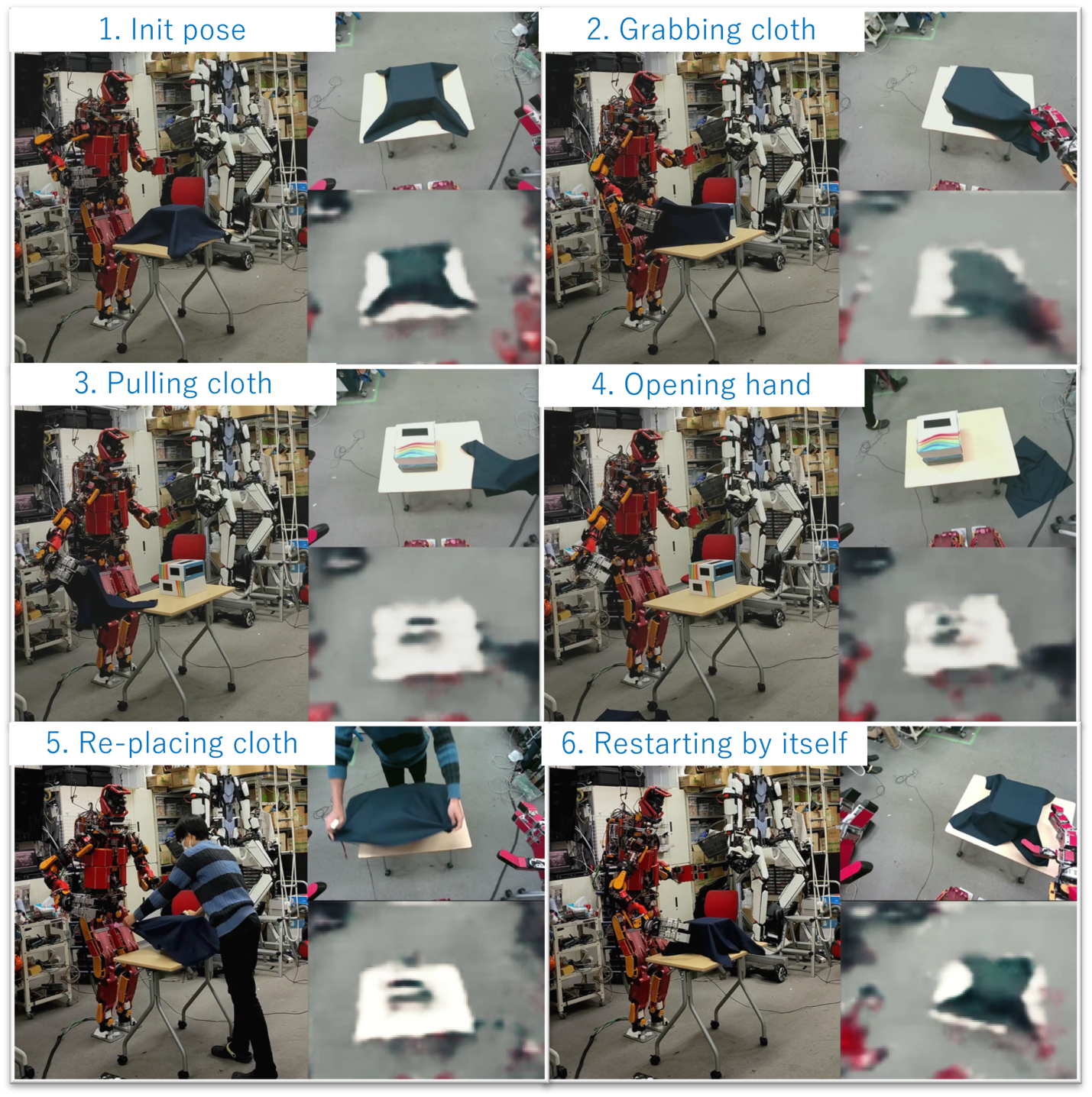
To confirm whether the robot was able to imitate, we compared the changes in finger angles during teleoperation and during autonomous work after learning, and found that the timing of angle changes and the maximum and minimum angles were similar.
VI-B Experiments on manipulating objects with a foot
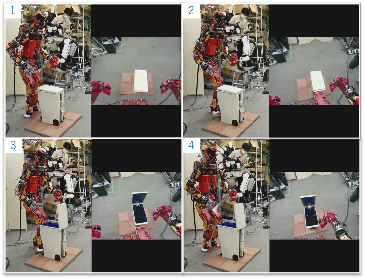
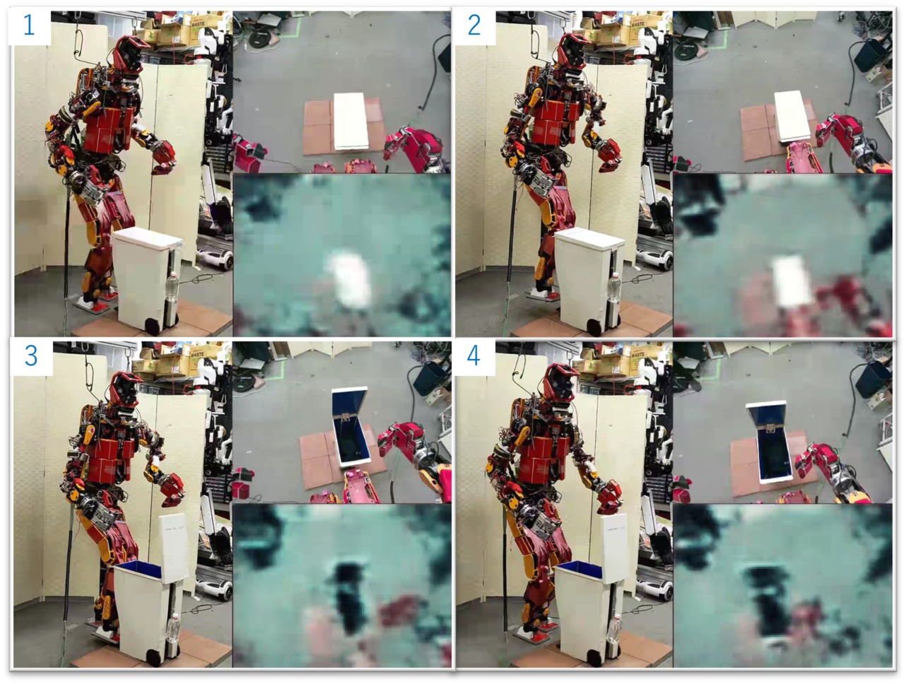
A humanoid opening a trash can using its legs is shown in Fig.7. The right image is from a camera on the robot’s head. First, the position of the operator’s feet is obtained and is calculated by the proposed system. When the difference between the heights of the two feet in the calculated posture exceeds a threshold value (6 cm), the system stops the maneuver and sends a trigger to the Whole Body Controller from Foot Step Commander to switch from the biped walking mode to the one-legged standing mode. After the transition, the operator resumes control of the robot’s legs. In the one-leg standing mode, the force sensor value is feedbacked to the operator with a low gain, therefore allowing the operator to recognize the contact with the trash can pedals and the reaction force when operating the trash can. After opening the trash can, the same procedure is reproduced in reverse, returning the feet to the ground. Again, the difference in the heights of the two feet is detected and the mode is switched. The work after learning is shown in Fig.8. The upper right is the camera image of the robot’s head, and the lower right is the image decoded through Auto Encoder. The control including the switching of the contact state of the feet was successful.
VI-C Whole-body heavy object manipulation
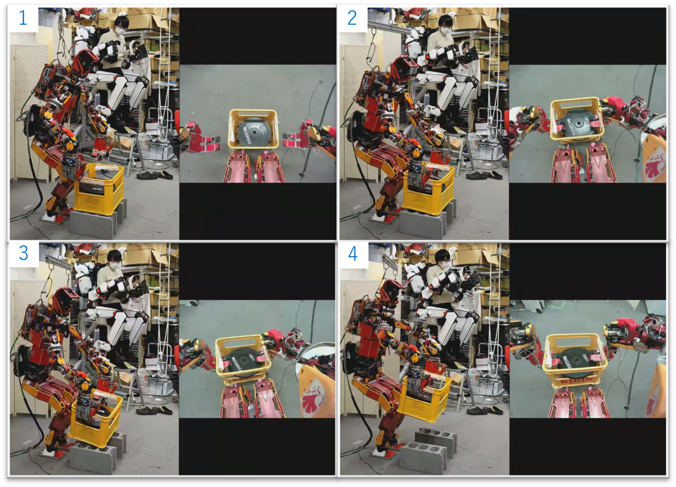
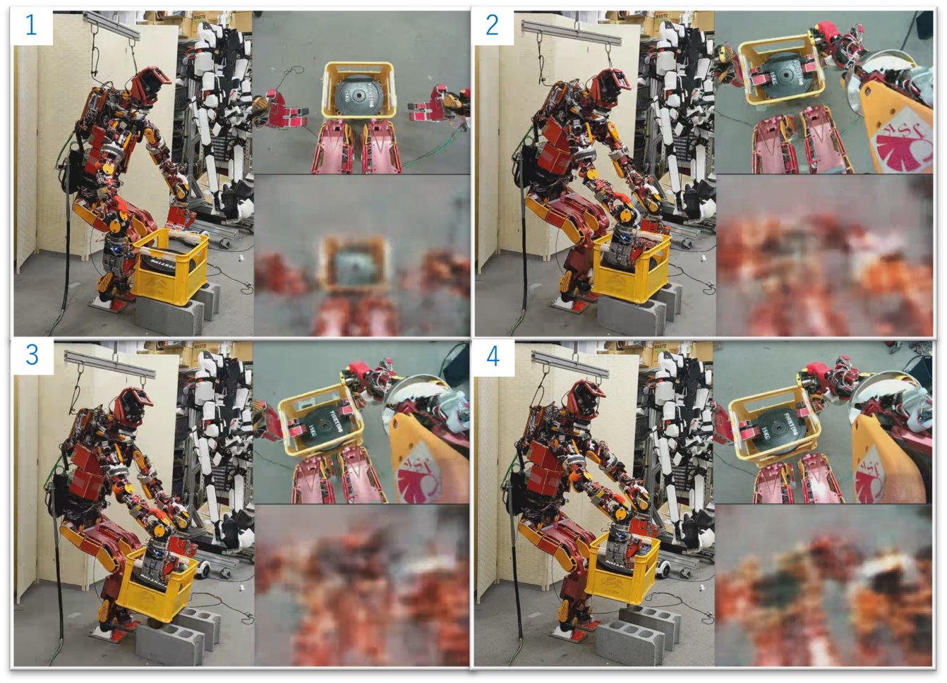
Here we worked on lifting a heavy box weighing approximately 16 kg. Bending with the knees and maintaining balance by taking into account the reaction force of the hands are important. Teaching by teleoperation is shown in Fig.9. The robot starts work from the initial posture with the index and middle fingers locked at 90 degrees. Both hands were inserted into the box handles and lifted vertically when a reaction force was felt, using teleoperation. Thanks to the teleoperation system’s constraint on the height of the center of gravity, when the height of the hand tip was lowered, the robot bent its knees and tilted the root link to lower its center of gravity. Since humanoid robots have the strong constraint of standing on two legs, balance control, such as changing the position of the center of gravity based on the external force of the hand tip, is indispensable, especially when manipulating heavy objects. In the proposed system, a constraint to keep the center of gravity at the center of the foot flat is added in the optimized posture generation, and the balance is maintained by using feedback control to shift the center of gravity position according to the sensor values of the hand tip. To cope with the time delay caused by the low-pass filter for the force sensor values, it was necessary to move the hand slowly enough at the beginning of lifting, when the external force on the hand tip changes significantly. The work with the learning is shown in the Fig.10. By inserting both hands against the handles and shifting the center of gravity appropriately, the lifting task was successfully performed while maintaining balance. In the experiment, even when the first insertion motion failed and the box shifted from the initial position, the robot autonomously reinserted its hands into the appropriate position again. The robustness of the imitation learning was also confirmed by the robot’s autonomous recovery behavior.
VII DISCUSSION
We discuss the limitations of this study in terms of the teleoperation method, the control including optimization calculations, and the learning method. First, regarding the method of manipulation, in the present study, the operator performed the work while looking directly at the object. Ideally, however, a method such as presenting the robot’s camera image through VR goggles should be adopted. On the other hand, in such a case, the camera angle of view would change significantly, and the generalization ability of imitation learning might be significantly reduced. In addition, since this system automatically determines the position and posture of links other than the limbs, the operator cannot control them. Therefore, it is difficult to bring the links into active contact with the environment, such as pushing an object with the waist. This problem can be solved by acquiring the positional posture of the operator’s hips and elbows, but it conflicts with optimization calculations and autonomous balance control. In this system, we developed the system from the standpoint that the tilt of the hips, etc. should be determined automatically, and that individual environmental contacts, etc. should be handled by the planner, not by the pilot. Furthermore, while MSLHAND has 3 fingers and 5 DOFs, the maneuvering interface has only 1 DOF. There are ways to control the fingers according to the object from a software perspective or to improve the maneuvering interface. Next, regarding the optimization calculation, currently, the weight parameters for the objective function and constraints are adjusted by a person according to the task. Ideally, these parameters should be adjusted automatically. It is thought that a generalized algorithm for determining weights can be given by a person. A small limitation also exists concerning balance control, which is the need to switch modes. In the previous system by Ishiguro et al., the legs could be moved in the same way as the arms without switching modes. However, this system sends a trigger when it becomes one leg. This is because the contact state cannot be changed in the two-legged mode, which has the function of fixing contact between both feet and the ground to maintain balance and the autonomous foot step-out function to avoid tipping over. This is a problem related to the combination of the operator’s command and the robot’s autonomous balance control, and this system gives priority to autonomous balance control. This is one of the issues that should be solved by devising the control theory and interface. Finally, regarding the learning method, in the present study, the robot learned by explicitly giving the start and end points of the work, but ideally, the robot should be able to automatically determine the breakpoints and learn. To achieve this, for example, it is possible to segment the work based on the position and posture of the object.
VIII CONCLUSIONS
This study aimed to develop an imitation learning system with a bipedal robot with a floating link. For this purpose, we developed a teleoperation system that connects a bilateral whole-body maneuvering device and a highly durable humanoid robot. Here, we introduced a torque/contact force-optimized posture generation method to make the system capable of withstanding long hours of data collection. Using this system, we successfully imitated flexible fabric manipulation, object manipulation with feet, and lifting of heavy objects where the pose change of the root link and center-of-gravity shift are critical.
References
- [1] Y. Ishiguro, T. Makabe, et al., “Bilateral humanoid teleoperation system using whole-body exoskeleton cockpit tablis,” IEEE Robotics and Automation Letters, vol. 5, no. 4, pp. 6419–6426, 2020.
- [2] R. Shigematsu, M. Murooka, Y. Kakiuchi, K. Okada, and M. Inaba, “Generating a key pose sequence based on kinematics and statics optimization for manipulating a heavy object by a humanoid robot,” in 2019 IEEE/RSJ International Conference on Intelligent Robots and Systems, pp. 3852–3859, 2019.
- [3] K. Kawaharazuka, Y. Kawamura, K. Okada, and M. Inaba, “Imitation learning with additional constraints on motion style using parametric bias,” IEEE Robotics and Automation Letters, vol. 6, no. 3, pp. 5897–5904, 2021.
- [4] T. Zhang, Z. McCarthy, O. Jowl, D. Lee, X. Chen, K. Goldberg, and P. Abbeel, “Deep imitation learning for complex manipulation tasks from virtual reality teleoperation,” in 2018 IEEE International Conference on Robotics and Automation (ICRA), pp. 1–8, 05 2018.
- [5] J. Schulman, J. Ho, C. Lee, and P. Abbeel, “Learning from demonstrations through the use of non-rigid registration,” in International Symposium of Robotics Research, 2013.
- [6] T. Osa, J. Pajarinen, G. Neumann, J. A. Bagnell, P. Abbeel, and J. Peters, “An algorithmic perspective on imitation learning,” Foundations and Trends in Robotics, vol. 7, no. 1-2, pp. 1–179, 2018.
- [7] M. Ito, K. Noda, Y. Hoshino, and J. Tani, “Dynamic and interactive generation of object handling behaviors by a small humanoid robot using a dynamic neural network model,” Neural Networks, vol. 19, no. 3, pp. 323–337, 2006. The Brain Mechanisms of Imitation Learning.
- [8] K. Noda, H. Arie, Y. Suga, and T. Ogata, “Multimodal integration learning of robot behavior using deep neural networks,” Robotics and Autonomous Systems, vol. 62, no. 6, pp. 721–736, 2014.
- [9] Z. Zhang, Y. Niu, Z. Yan, and S. Lin, “Real-time whole-body imitation by humanoid robots and task-oriented teleoperation using an analytical mapping method and quantitative evaluation,” Applied Sciences, vol. 8, no. 10, 2018.
- [10] P.-C. Yang, K. Sasaki, K. Suzuki, K. Kase, S. Sugano, and T. Ogata, “Repeatable folding task by humanoid robot worker using deep learning,” IEEE Robotics and Automation Letters, vol. 2, no. 2, pp. 397–403, 2017.
- [11] K. Kojima, T. Karasawa, et al., “Development of life-sized high-power humanoid robot JAXON for real-world use,” in 2015 IEEE-RAS 15th International Conference on Humanoid Robots (Humanoids), pp. 838–843, Nov. 2015.
- [12] Y. Ariki, T. Matsubara, and S.-H. Hyon, “Latent kullback-leibler control for dynamic imitation learning of whole-body behaviors in humanoid robots,” in 2016 IEEE-RAS 16th International Conference on Humanoid Robots (Humanoids), pp. 946–951, 2016.
- [13] M. Muhlig, M. Gienger, S. Hellbach, J. J. Steil, and C. Goerick, “Task-level imitation learning using variance-based movement optimization,” in 2009 IEEE International Conference on Robotics and Automation (ICRA), pp. 1177–1184, 2009.
- [14] Y. Matsuura, N. Hiraoka, K. Kojima, I. Yanokura, H. Yoshioka, K. Okada, and M. Inaba, “Development of a multi-fingered hand with a multi-step locking mechanism for carrying heavy objects by a humanoid robot,” in 2022 IEEE-RAS 21th International Conference on Humanoid Robots (Humanoids), pp. 794–800, November 2022.
- [15] S. Hochreiter and J. Schmidhuber, “Long short-term memory,” Neural computation, vol. 9, no. 8, pp. 1735–1780, 1997.
- [16] D. P. Kingma and J. Ba, “Adam: A Method for Stochastic Optimization,” in ICLR2015, pp. 1–15, 2015.
- [17] G. E. Hinton and R. R. Salakhutdinov, “Reducing the Dimensionality of Data with Neural Networks,” Science, vol. 313, no. 5786, pp. 504–507, 2006.